Whole-Building Delivered Ventilation
Scope

Design a whole-house ventilation system that complies with all relevant codes and standards and provides adequate indoor air quality. ENERGY STAR Certified Homes Revision 08 requires homes to meet ASHRAE 62.2-2010 or 2013.
- Ensure that fans meet required air flow and noise levels.
- Make sure all outdoor air inlets draw air from outdoors (not from attic, crawlspace, garage, or adjacent dwelling unit) and that the inlet is located at least 10 feet from contaminant sources and 2 feet above grade.
- Vent exhaust fans to the outside, not into the attic.
See the Compliance Tab for related codes and standards requirements, and criteria to meet national programs such as DOE’s Zero Energy Ready Home program, ENERGY STAR Certified Homes, and Indoor airPLUS.
Description
Ventilation systems are designed to meet two different tasks: spot ventilation and whole-building ventilation. Spot ventilation is for specific, non-continuous tasks such as removing moisture generated from cooking, bathing, etc. The following guides provide information about spot ventilation:
Whole-building mechanical ventilation is designed to provide a healthy indoor environment. The key to any healthy indoor environment is first to minimize the introduction of pollutants by:
- Using no/low VOC building and furnishing products
- Properly air sealing exterior walls and foundations to prevent soil off-gases from entering the home
- Install only direct vent combustion equipment
After preventative measures have been taken, whole house ventilation can be used to dilute and remove the remaining pollutants. There are three common types of mechanical ventilation used to meet the requirements outlined by the DOE Zero Energy Ready Home and ENERGY STAR programs: supply-only ventilation, exhaust-only ventilation, and balanced air ventilation. Although the latest ENERGY STAR requirements allow ventilation rates consistent with either ASHRAE 62.2-2010 or 2013, this guide will refer to ASHRAE 62.2-2010 whenever "ASHRAE 62.2" is mentioned.
Supply-Only Ventilation
Supply-only ventilation uses the HVAC system supply fan to pull in air from outdoors through a dedicated outdoor air intake. The outdoor air is typically filtered, conditioned, and circulated throughout the building with additional equipment. With supply-only ventilation, outdoor air enters the building from a known location and stale air leaves the building through an unknown location (through leaks in the building shell). The outdoor air is ducted from an intake located where the ambient air is deemed to be clean and where the intake grille is easy to access (for example, in a porch ceiling) for maintenance and changing of the filter, which is typically in the outdoor register grille. Outdoor air intakes should be at least 10 feet from the nearest exhaust or sanitary vent termination point.
Supply-only ventilation will create a positive pressure in the conditioned space relative to outdoors. This strategy typically depends on building envelope leaks to exit the stale air. If the systems in Figures 1 and 2 were drawing 80 CFM of outdoor air into the home while the air handler is operating, then at the same time 80 CFM must be exiting the building somewhere. That "somewhere" is the many leaks in the building envelope that connect indoors to outdoors. In humid climates where the conditioned indoor air is dryer than outdoor air, this is a good strategy; it will help keep building envelope materials (the insides of the walls) dry while providing ventilation air that is ideally both filtered and dehumidified. In cold, dry climates where indoor air is more humid than outdoor air (in high-performance buildings), supply-only ventilation would be a poor ventilation strategy.
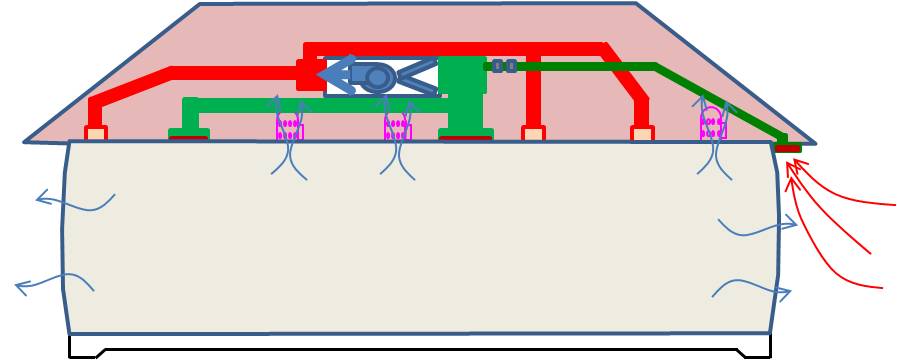
Figure 1 - With supply-only ventilation, the building is under positive pressure. ![]()
The success of this strategy is dependent upon good design: an accurate HVAC load calculation, installation of HVAC equipment that closely matches the load, and a properly designed HVAC duct system. It is imperative that the cooling system not be oversized so that it will get maximum run time during 1% summer outdoor design conditions (as defined in ACCA Manual J, Table 1). If the designed target ventilation hourly rates are based on average cooling run time, oversizing the cooling or heating system will produce a ventilation rate that will be far short of the target ventilation rate.
Central Fan Integrated Supply Ventilation
One common type of supply ventilation system is known as central fan integrated supply ventilation. When the cooling or heating system is energized, outdoor air is drawn into a filtered intake grille and is ducted directly to the return side plenum of the air handler. The outdoor air duct has a balancing damper (BD), which is manually set to adjust the amount of incoming outside air to meet the target cubic feet per minute flow rate determined in the Manual D calculations. In dry climates, this fresh air intake duct is open all the time and provides a dedicated passive opening for makeup air.

Figure 2 - The central fan integrated supply ventilation system can provide whole-house ventilation while bathroom and kitchen exhaust fans provide spot ventilation. ![]()
In humid climates (those where the average outdoor dew point is often in the mid 70s), the outside air duct is equipped with a second damper. This is a motorized damper and is referred to as the outdoor air damper (ODAD); it is only open when the compressor is operating so that the incoming outdoor air is dehumidified before it enters the conditioned space. The ODAD prevents pulling warm humid air into the system when the compressor is not operating. This prevents condensation from taking place on the internal parts of the air handler or furnace which can eventually cause the parts to rust. Because the ODAD is only open and allowing active ventilation when the compressor is operating, this system is known as a run-time vent.
The run-time vent system would not meet ASHRAE 62.2 during shoulder seasons because the compressor does not operate enough, so an electronic controller is added to control the motorized damper. The controller counts the minutes the cooling is running and after an hour, if the ASHRAE 62.2 minutes requirement has not been met, the controller will open the damper and turn on the fan to make up the minutes. However, the controller will not open the damper unless the compressor has been off for at least 5 minutes. The 5 minutes gives all of the air handler parts enough time to warm up so that the humid air that enters the unit won’t condense on cold parts, potentially causing equipment damage.
In a humid climate, to meet ASHRAE 62.2, active dehumidification must be added to the run-time vent system to handle the moisture that is brought in during the shoulder seasons when the damper is open and the compressor is not operating. In Florida, when it is 95°F outside, the compressor (AC) runs about 80% of the time. When it is 80°F outside, the compressor only runs about 40% to 50% of the time. The dehumidifier can be a separate unit attached to the central air handler or a stand-alone unit.
Exhaust-Only Ventilation
Exhaust-only ventilation is the reverse of supply-only ventilation; stale air leaves the building from a known location (through exhaust fans ducted to the outdoors) and outdoor air enters the building from an unknown location. For every cubic foot of air exhausted out of the building, a cubic foot of air has to come into the building from somewhere. Again, that "somewhere" is the many air leaks through the building envelope that connect the conditioned space to unconditioned spaces or directly to the outdoors. With this strategy, the outdoor air entering the building is neither filtered nor conditioned. The target ventilation rate is met by operating a (quiet) exhaust fan at a specific flow rate for a scheduled runtime each hour.
This strategy works well in cold-dry climates because the air outdoors is generally drier than the air indoors (in tightly built homes). Unlike the older, leaky homes built years ago, newer high-performance homes are built to be more air tight so they tend to accumulate more moisture as water vapor in the indoor air from cooking, bathing, clothes washing, etc. Exhaust-only ventilation is needed to safely remove this moisture before condensation becomes an issue.
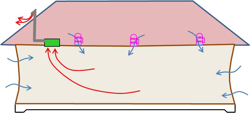
Figure 3 - With exhaust-only ventilation, the building is under negative pressure. ![]()
The make-up air moving through the building envelope helps to keep building materials dry when this strategy is used in cold, dry climates. This would not be a good strategy in humid climates where the water vapor content outdoors is typically higher than it is indoors.
Balanced Ventilation
Balanced systems intentionally provide both supply and exhaust. The best means for providing this balanced ventilation is with a heat recovery ventilator (HRV) or an energy (or enthalpy) recovery ventilator (ERV). Both provide a controlled way of ventilating a home while minimizing energy loss because they incorporate a heat exchanger that uses conditioned air from the outgoing exhaust air to pre-condition the "fresh" incoming air. The heat exchanger transfers heat but does not allow the intermingling of outgoing and incoming air.

Figure 4 - Heat Recovery Ventilator (HRV) or Energy (Enthalpy) Recovery Ventilator (ERV). ![]()
The incoming and outgoing air volumes are balanced and air is evenly distributed throughout the house. These ventilators are whole-house systems. Although they can share the central furnace’s air handler and duct system, ideally, these systems have their own duct system. The main difference between an HRV and an ERV is the way the heat exchanger works.
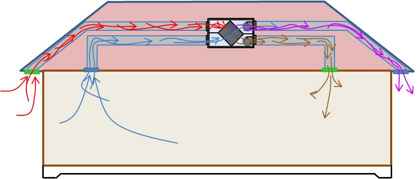
Figure 5 - An HRV or ERV provides balanced ventilation by pulling in the same amount of outdoor air that is being exhausted back to the outdoors. ![]()
With an ERV, the heat exchanger transfers water vapor along with heat energy, while an HRV only transfers heat. See the manufacturers' specifications for determining which model is best in which climate and install it according to their directions for best performance, especially in regard to ERVs in humid climates. Most ERVs can recover about 70% to 80% of the sensible energy in the exiting air (Rudd 2011). With respect to summertime operation, ERVs seem to perform best during peak outdoor conditions and lose efficiency during low-temperature, high-humidity conditions.
Intermittently Balanced
Another ventilation strategy that is somewhat controversial among experts is the "itermittently balanced" system, which combines supply and exhaust but does not include an HRV or ERV (Rudd 2011). Supply and exhaust ventilation systems are combined to make use of the benefits and economies of each system, although the net result may be an alternating unbalanced system (sometimes supply ventilation and sometimes exhaust ventilation), or an intermittently balanced system, or a fully balanced system (if carefully controlled with electronic controllers to provide equal amounts of incoming and outgoing air). An example of this type of system could be central-fan-integrated supply ventilation with simultaneous continuous or intermittent exhaust. Another strategy could be to provide a background level of distributed supply ventilation coincident with heating and cooling demand then activate “fill-in” exhaust during the balance of the time (Rudd 2011).
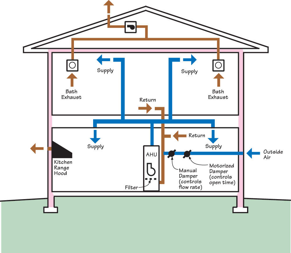
Figure 6 - Central-fan-integrated supply ventilation with single- or multi-point exhaust from bathrooms, for intermittently balanced whole-house ventilation. ![]()
How to Calculate the Target Ventilation Level Using ASHRAE 62.2-10
1. Calculate the target ventilation rate for the home based on the square footage of floor area and number of bedrooms, using the formula in Figure 7 from Formula 4.1a in ASHRAE 62.2-2010.

Figure 7 - Target Ventilation, Formula 4.1a from ASHRAE 62.2-2010
2. Once the target ventilation has been identified, select a ventilation strategy that will best do the job given the climate (see Description above).
3. Determine the operating time - how long will the fan have to run to supply the target ventilation for each 24-hour period?
4. Install the system according to the manufacturer's specifciations.
Example - for a 3-bedroom, 2,000-sq.ft. home, with an exhaust-only ventilation strategy, and a target ventilation rate of 50 CFM you would need to install a 50 CFM fan with an adjustable-speed DC motor for continuous operation. If you wanted to install a 100 CFM fan instead, you could determine what the run time would need to be using the formula below (Figure 9), from ASHRAE 62.2-2010.

Figure 8 - Formula 4.2 for fan flow rate required to achieve an effective ventilation rate from ASHRAE 62.2-2010
Considering that we want the fan to run at least once in a four-hour period, our Ventilation Effectiveness (e) is 1.0 (see Table 4.2, which shows 1.0 for cycle time of 0-4 meaning that the fan would run at least once in each four-hour period or six times in a day. Also the designer has determined that the Fraction On-Time will be 0.5 or 50% of the time. So to calculate the required fan air flow (Qf) to meet the target ventilation rate (Qr) based on an intermittent run time, the calculation would look like this:
Q f = Q r / (ef)
Q f = 50 CFM / (1.0 x 0.5)
Q f = 50 /0.5
100 = 50 / 0.5
So, 100 CFM is the size of the fan that is required if we are going to run the fan at least once every four hours for 50% of the time to meet the target ventilation rate. The fan could be set with a controller on any timer schedule that would meet the 50% run time, for example 10 minutes on-10 minutes off, or 30 minutes per hour, etc.
Ensuring Success
After source control, air changes in a home are the most important factor in decreasing pollution concentrations. In existing homes with natural air change rates above 0.35 ACH, ventilation occurs somewhat naturally through gaps and cracks in the enclosure. In newer homes, with natural air change rates less than 0.35 ACH, additional mechanical ventilation has been shown to help decrease pollutant concentrations of dangerous aldehydes like formaldehyde and acetaldehyde. The following table of featured Zero Energy Ready Home (ZERH) builders depicts how balanced ventilatiton is the preferred choice of ventilation systems in all climates.
Table 1. Ventilation Types Installed by Zero Energy Ready Home Builders

As seen in the table above, balanced ventilation is recommended for all climate regions. When balanced ventilation is not an option, due to cost constraints, supply ventilation is recommended for all climates except for the cold climate region where condensation in the enclosure is a factor. In humid climates, the tightening of homes due to more stringent codes has led to increased humidity. Therefore, it is recommended that a supplimental dehumidification strategy is implemented in that climate.
Climate
Humid Climates
In hot-humid climates (Baechler et al, 2010), when appropriate levels of ventilation are used to remove pollutants, moist outdoor air is also moved through the building. With increased ventilation rates, humidity levels tend to increase as well (Fairey et al, 2014, Hodgson et al., 2005, Rudd et al., 2005), sometimes even above threshold limits for mold and mildew growth. This results in quite the conundrum for builders and designers in those areas. For these homes, field research (Hodgson et al., 2005, Kerrigan and Norton, 2014) suggests that there adding supplimental dehumidification can help minimize the time that indoor humidity levels are above critical levels (approximately 60% RH).
Consider a 2,500 sq.ft., four-bedroom home. The required ventilation rate would be 63 CFM. In a hot-humid climate like Sarasota, Florida, according to the ACCA Manual J Table 1, the outdoor 1% summer design condition is 92°F with a coincidental wet bulb of 79°F. The moisture content of the air is 129 grains per pound of air. A pound of air occupies about 14.3 cubic feet. So our target ventilation will move about 4.4 (63/14.3) pounds of air into the building per minute. Also, with it comes 5,676 (4.4x129) grains of moisture. In an hour, we have transported 340,560 grains of moisture. There is 7,006 grains of moisture in one pound of water (roughly one pint). Thus, the target ventilation will bring in 48 pints or 3 gallons of water during one-hour of operating time; that is equivalent to moving 72 gallons of water through the home in a 24-hour period.
With no active dehumidification, the home accumulates water until the grains per pound of air indoors is equal to the grains per pound of air outdoors. In the Sarasota, Florida, area where the moisture levels are 129 grains per pound of air outdoors, it will be 129 grains per pound indoors. If the home had 8-foot ceilings, it would contain 20,000 cubic feet or about 1,428 pounds of air. At 129 grains per pound, there would be about 26 pints of water in vapor form in the air at all times. If the AC system was oversized and it could easily maintain 75°F with very little run time, the indoor relative humidity would be 98% and the dew point would be 74°F.
Training
Videos
-
 Publication Date: July, 2015Courtesy Of: Zero Energy Homes
Video describing how heat recovery ventilation systems.
CAD Images
None Available
Compliance
ENERGY STAR Certified Homes (Version 3/3.1, Revision 08), Rater Field Checklist
7. Whole-House Mechanical Ventilation System
7.1 Rater-measured ventilation rate is within either ± 15 CFM or ±15% of design value (2.3)42
Footnotes:
(42) The whole-house ventilation air flow and local exhaust air flows shall be measured by the Rater using RESNET Standard 380 upon publication and, in the interim, a flow hood, flow grid, anemometer, or substantially equivalent method.
ENERGY STAR Revision 08 requirements are required for homes permitted starting 07/01/2016.
Exhibit 1: Mandatory Requirements. Certified under ENERGY STAR Qualified Homes Version 3.
Associated Air Barrier Council National Standards for Total System Balance
Associated Air Barrier Council, 2002. AABC National Standards for Total System Balance 2002. The manual details the minimum standards for total system balance.
National Environmental Balancing Bureau Section 15990
National Environmental Balancing Bureau (NEBB) Section 15990 – Testing, Adjusting, and Balancing. NEBB is a certification association whose members perform testing, adjusting and balancing (TAB) of heating, ventilating, and air-conditioning systems and commission and retro-commission building systems. This document is the TAB procedural standards.
ANSI/ASHRAE Standard 62.2.-2010
Ventilation and Acceptable Indoor Air Quality in Low-Rise Residential Buildings. The standard applies to spaces intended for human occupancy in single-family homes and multifamily homes that are three stories or less, including manufactured and modular homes. The standard provides minimum acceptable requirements for mechanical and natural ventilation in these spaces.
ANSI/ASHRAE Standard 62.2-2013
Ventilation and Acceptable Indoor Air Quality in Low-Rise Residential Buildings. The standard applies to spaces intended for human occupancy in single-family homes and multifamily homes that are three stories or less, including manufactured and modular homes. The standard provides minimum acceptable requirements for mechanical and natural ventilation in these spaces.
Section M1507.3 Whole-house mechanical ventilation system. The system is to have one or more supply or exhaust fans, or a combination, and associated ducts and controls. Local exhaust or supply fans can serve as such. Outdoor air ducts connected to the return side of an air handler are considered to provide supply ventilation. The system must have controls with manual override capability. The system must provide outdoor air at a continuous rate per Table M1507.3.3(1) which is based on dwelling unit floor area and number of bedrooms.*
*Due to copyright restrictions, exact code text is not provided. For specific code text, refer to the applicable code.
More Info.
Balanced Ventilation = Fresh Air Balanced System

Balanced ventilation systems supply fresh air while removing an equal amount of air. This type of system maintains a neutral balance in air pressure that avoids slamming doors. These systems can be configured to use outgoing air to preheat or cool the incoming air to further improve comfort and save energy. Some systems also exchange moisture between incoming and outgoing air to help control indoor humidity. Incoming air is typically filtered
Alternate Terms
Sales Message
