| 1400 |  |
Nautical chart of New York Harbor, 1845. There were earlier sketches of harbors. But this was the first chart produced with the distinctive Coast Survey style |
|
1401 |  |
Nautical chart of New York Harbor, ca. 1924. New style chart with yellow land, blue water, and colored buoys. Basically, this is the format for NOAA nautical charts today |
|
1402 |  |
Nautical chart of Annapolis Harbor, Maryland, 1846. |
|
1403 |  |
Portion of nautical chart of San Francisco Bay entrance, 1859. Showing the Golden Gate and Alcatraz Island street layout, and wharves |
|
1404 |  |
Monterey Harbor with view of Point Pinos lighthouse, 1852. |
|
1405 |  |
"New type" chart, San Diego to Santa Cruz Island, California, 1936. Chart incorporated bathymetric contours to show bottom detail as navigation aid |
|
1406 |  |
Chart of Agusan River Entrance and inset of Nasipit Harbor, Philippine Islands. |
|
1407 |  |
Chart of Agusan River Entrance, Philippine Islands. Chart has contours drawn by Paul A. Smith showing head of submarine canyon |
|
1408 |  |
Chart of northwest coast of United States, Gray's Harbor to Admiralty Inlet. From reconnaissance survey of Lt. Cmdg. James Alden, 1853. |
|
1409 |  |
Detail of views on 1853 chart of northwest coast. |
|
1410 |  |
Description not available. |
|
1411 |  |
Description not available. |
|
1412 |  |
Description not available. |
|
1413 |  |
Description not available. |
|
1414 |  |
Description not available. |
|
1415 |  |
Description not available. |
|
1416 |  |
Description not available. |
|
1417 |  |
Description not available. |
|
1418 |  |
Description not available. |
|
1419 |  |
Description not available. |
|
1420 |  |
Description not available. |
|
1421 |  |
Description not available. |
|
1422 |  |
Description not available. |
|
1423 |  |
Description not available. |
|
1424 |  |
Description not available. |
|
1425 |  |
Description not available. |
|
1426 |  |
Description not available. |
|
1427 |  |
Description not available. |
|
1428 |  |
Description not available. |
|
1429 |  |
Tape contact at middle of comparator. Basically calibrating steel tapes - first use of steel measuring tapes by C&GS. Nine bases being measured on 98th Meridian by base line party under A.L. Baldwin . Fig. No. 15, Appendix No. 3, Report of Superintendent ... 1901, p. 260. Work done at night to reduce expansion and contraction of steel tape |
1901 |
1430 |  |
Tape contact at end of comparator. Basically calibrating steel tapes - first use of steel measuring tapes by C&GS. Nine bases being measured on 98th Meridian by base line party under A.L. Baldwin . Fig. No. 14, Appendix No. 3, Report of Superintendent ... 1901, p. 260 |
1901 |
1431 |  |
Cut-off, i.e. flashlight, in use at night on comparator. Night-time operations in comparing lengths of steel tapes. Fig. No. 13, Appendix No. 3, Report of Superintendent ... 1901, p. 258 |
1901 |
1432 |  |
After making contact, the forward end of tape is moved ahead. Note lantern and flashlight - these operations were conducted at night. Relatively constant night temperatures minimized expansion of tape. Fig. No. 12, Appendix No. 3, Report of Superintendent ... 1901, p. 258 |
1901 |
1433 |  |
Making contact at rear end of tape. Man standing is maintaining pre-set constant tension on line. Man kneeling is reading tape. Fig. No. 11, Appendix No. 3, Report of Superintendent ... 1901, p. 258 |
1901 |
1434 |  |
Aligning iced-bar base apparatus with striding level. Assuring iced-bar apparatus is horizontal. Fig. No. 5, Appendix No. 3, Report of Superintendent ... 1901, p. 244. |
1901 |
1435 |  |
Stone marking end of comparator, a 100-meter very stable short base line. Comparator was used to calibrate and intercompare various measuring instruments . This comparator was at Shelton, Nebraska, near Station Shelton East Base. Fig. No. 2, Appendix No. 3, Report of Superintendent ... 1901, p. 244 |
Shelton, Nebraska 1901 |
1436 |  |
Plane table alidade. Plate IV, Fig. No. 10, Appendix No. 8, Report of Superintendent ... 1894, p. 276 |
1894 |
1437 | 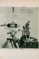 |
Magnetometer and altazimuth instrument. Plate III, Fig. No. 9, Appendix No. 8, Report of Superintendent ... 1894, p. 276 |
1894 |
1438 |  |
Aligning support nails for steel tapes. Fig. No. 10, Appendix No. 3, Report of Superintendent ... 1901, p. 258 |
1901 |
1439 |  |
Duplex measures, carrying the rear bar ahead. After making contact, the rear bar was moved to the forward position. It was then realigned horizontally, vertically, and for azimuth on the base line . Fig. No. 9, Appendix No. 3, Report of Superintendent ... 1901, p. 244 |
1901 |
1440 |  |
Duplex measures, ready to launch the rear bar. After making contact, the rear bar was moved to the forward position. It was then realigned horizontally, vertically, and for azimuth on the base line . Fig. No. 8, Appendix No. 3, Report of Superintendent ... 1901, p. 244 |
1901 |
1441 |  |
Duplex measures, making the final contact. "Contact" meant bringing the two aligned bars together so the ends were touching . Fig. No. 7, Appendix No. 3, Report of Superintendent ... 1901, p. 244. |
1901 |
1442 |  |
Using Eimbeck duplex base-line measurement apparatus. Aligning duplex bar horizontally and vertically. Fig. No. 6, Appendix No. 3, Report of Superintendent ... 1901, p. 244. |
1901 |
1443 |  |
Theodolite magnetometer. Fig. No. 29, Report of Superintendent ... 1865 |
1865 |
1444 |  |
Portable transit. Fig. No. 29, Report of Superintendent ... 1866 |
1866 |
1445 | 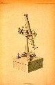 |
Zenith telescope. Fig. No. 28, Report of Superintendent ... 1866 |
1866 |
1446 | 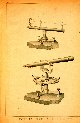 |
Twelve inch repeating circle (bottom) and heliotrope (top). Fig. No. 27, Report of Superintendent ... 1866 |
1866 |
1447 |  |
Thirty inch theodolite. Fig. No. 26, Report of Superintendent ... 1866 |
1866 |
1448 |  |
Transferring the measurement to the ground work. Completing the Salt Lake City Base. Distance measurement with Eimbeck base bar apparatus. Figure No. 9, Appendix No. 12. Part II, Report of the Superintendent ... 1897, p. 774 |
Salt Lake City, Utah 1897 |
1449 |  |
Crossing a railway embankment on the Salt Lake City Base. Using the Eimbeck base bar apparatus. Figure No. 8, Appendix No. 12. Part II, Report of the Superintendent ... 1897, p. 774 |
Salt Lake City, Utah 1897 |