- Lowest rate of use—11:30 pm to 5:00 am,
- Sharp rise/high use—5:00 am to noon (peak hourly use from 7:00 am to 8:00 am),
- Moderate use—noon to 5:00 pm (lull around 3:00 pm), and
- Increasing evening use—5:00 pm to 11:00 pm (second minor peak, 6:00 pm to 8:00 pm).
- Determine the quality needed for the intended purpose (drinking water quality needs to be evaluated under the SDWA).
- For wells and springs, test the water for bacteriologic quality. This should be done with several samples taken over a period of time to establish a history on the source. With few exceptions, surface water and groundwater sources are always presumed to be bacteriologically unsafe and, as a minimum, must be disinfected.
- Analyze for chemical quality, including both legal (primary drinking water) standards and aesthetic (secondary) standards.
- Determine the economical and technical restraints (e.g., cost of equipment, operation and maintenance costs, cost of alternative sources, availability of power).
- Treat if necessary and feasible.
- the groundwater aquifer to be developed,
- depth of the water-bearing formations,
- the type of rock formations that will be encountered,
- freedom from flooding, and
- relation to existing or potential sources of contamination.
- surface water entering directly into the top of the well,
- groundwater entering below ground level without filtering through at least 10 feet of earth, and
- surface water entering the space between the well casing and surrounding soil.
- find the source,
- properly develop the spring,
- eliminate surface water outcroppings above the spring to its source,
- prevent animals from accessing the spring area, and
- provide continuous chlorination.
- Liquid—Chlorine laundry bleach (about 5% chlorine). Swimming pool disinfectant or concentrated chlorine bleach (12%–17% chlorine).
- Powder—Chlorinated lime (25% chlorine), dairy sanitizer (30% chlorine), and high-test calcium hypochlorite (65%–75% chlorine).
- Tablets—High-test calcium hypochlorite (65%–75% chlorine).
- Gas—Gas chlorine is an economical and convenient way to use large amounts of chlorine. It is stored in steel cylinders ranging in size from 100 to 2,000 pounds. The packager fills these cylinders with liquid chlorine to approximately 85% of their total volume; the remaining 15% is occupied by chlorine gas. These ratios are required to prevent tank rupture at high temperatures. It is important that direct sunlight never reaches gas cylinders. It is also important that the user of chlorine knows the maximum withdrawal rate of gas per day per cylinder. For example, the maximum withdrawal rate from a 150-pound cylinder is approximately 40 pounds per day at room temperature discharging to atmospheric pressure.
- washbasins, sterilizers, and sinks with submerged inlets or threaded hose bibs and hose;
- oversized booster pumps that overtax the supply capability of the main and thus develop negative pressure;
- submerged inlets and fire pumps (if the fire pumps are directly connected into the water main, a negative pressure will develop); and
- a threaded hose bib in a health-care facility (which is technically a cross-connection).
- Vacuum breakers (nonpressure and pressure);
- Back-flow preventers (reduced pressure principle, double gate–double check valves, swing-connection, and air gap–double diameter separation);
- Surge tanks (booster pumps for tanks, fire system make-up tank, and covering potable tanks); and
- Color coding in all buildings where there is any possibility of connecting two separate systems or taking water from the wrong source (blue—potable, yellow—nonpotable, and other—chemical and gases).
- Periodically inspect exposed parts of wells for cracked, corroded, or damaged well casings; broken or missing well caps; and settling and cracking of surface seals.
- Slope the area around wells to drain surface runoff away from the well.
- Install a well cap or sanitary seal to prevent unauthorized use of, or entry into, a well.
- Disinfect wells at least once a year with bleach or hypochlorite granules, according to the manufacturer’s directions.
- Have wells tested once a year for coliform bacteria, nitrates, and other constituents of concern.
- Keep accurate records of any well maintenance, such as disinfection or sediment removal, that require the use of chemicals in the well.
- Hire a certified well driller for new well construction, modification, or abandonment and closure.
- Avoid mixing or using pesticides, fertilizers, herbicides, degreasers, fuels, and other pollutants near wells.
- Do not dispose of waste in dry or abandoned wells.
- Do not cut off well casings below the land surface.
- Pump and inspect septic systems as often as recommended by local health departments.
- Never dispose of hazardous materials (e.g., paint, paint stripper, floor stripper compounds) in a septic system.
- Rhode Island Department of Health and University of Rhode Island Cooperative Extension Water Quality Program. Healthy drinking waters for Rhode Islanders. Kingston, RI: Rhode Island Department of Health and University of Rhode Island Cooperative Extension Water Quality Program; 2003. Available from URL: http://www.uri.edu/ce/wq/has/html/Drinking.pdf.
- US Census Bureau. American housing survey. Washington, DC: US Census Bureau; 2003. Available from URL: http://www.census.gov/hhes/www/housing/ahs/nationaldata.html.
- US Census Bureau. Historical census of housing graphs: water supply. Washington, DC: US Census Bureau; no date. Available from URL: http://www.census.gov/hhes/www/housing/census/historic/swgraph.html.
- National Ground Water Association. Well system material. Westerville, OH: National Ground Water Association; 2003. Available from URL: http://www.ngwa.org/pdf/wellsystemmaterials.pdf.
- US Environmental Protection Agency. Spring development. Chicago: US Environmetal Protection Agency; 2001.
- Government of Alberta. Shock chlorination - well maintenance. Edmonton, Alberta, Canada: Alberta Agriculture, Food & Rural Development; 2001. Available from URL: http://www1.agric.gov.ab.ca/$department/deptdocs.nsf/all/wwg411.
- Boulder GNS Water Well Service and Supply. Chlorination of water systems. Boulder, CO: Boulder GNS Water Well Service and Supply; 2002. Available from URL: http://www.waterwell.cc/CHLORIN.HTM.
- Iowa State University Diagnosing and solving common water-quality problems. Ames, IA: Iowa State University; 1994. Available from URL: http://www.abe.iastate.edu/HTMDOCS/aen152.pdf.
Download Adobe Acrobat (PDF) version of this section - 1036KB
To order hard copies or CD-ROMs of the complete manual,
call 1-800-CDC-INFO.
“We never know the worth of water till the well is dry.”
Thomas Fuller
Gnomologia, 1732
One of the primary differences between rural and urban
housing is that much infrastructure that is often taken for granted by the urban
resident does not exist in the rural environment. Examples range from fire and police
protection to drinking water and sewage disposal. This chapter is intended to provide
basic knowledge about the sources of drinking water typically used for homes in
the rural environment. It is estimated that at least 15% of the population of the
United States is not served by approved public water systems. Instead, they use
individual wells and very small drinking water systems not covered by the Safe Water
Drinking Act; these wells and systems are often untested and contaminated [1].
Many of these wells are dug rather than drilled. Such shallow sources frequently
are contaminated with both chemicals and bacteria.
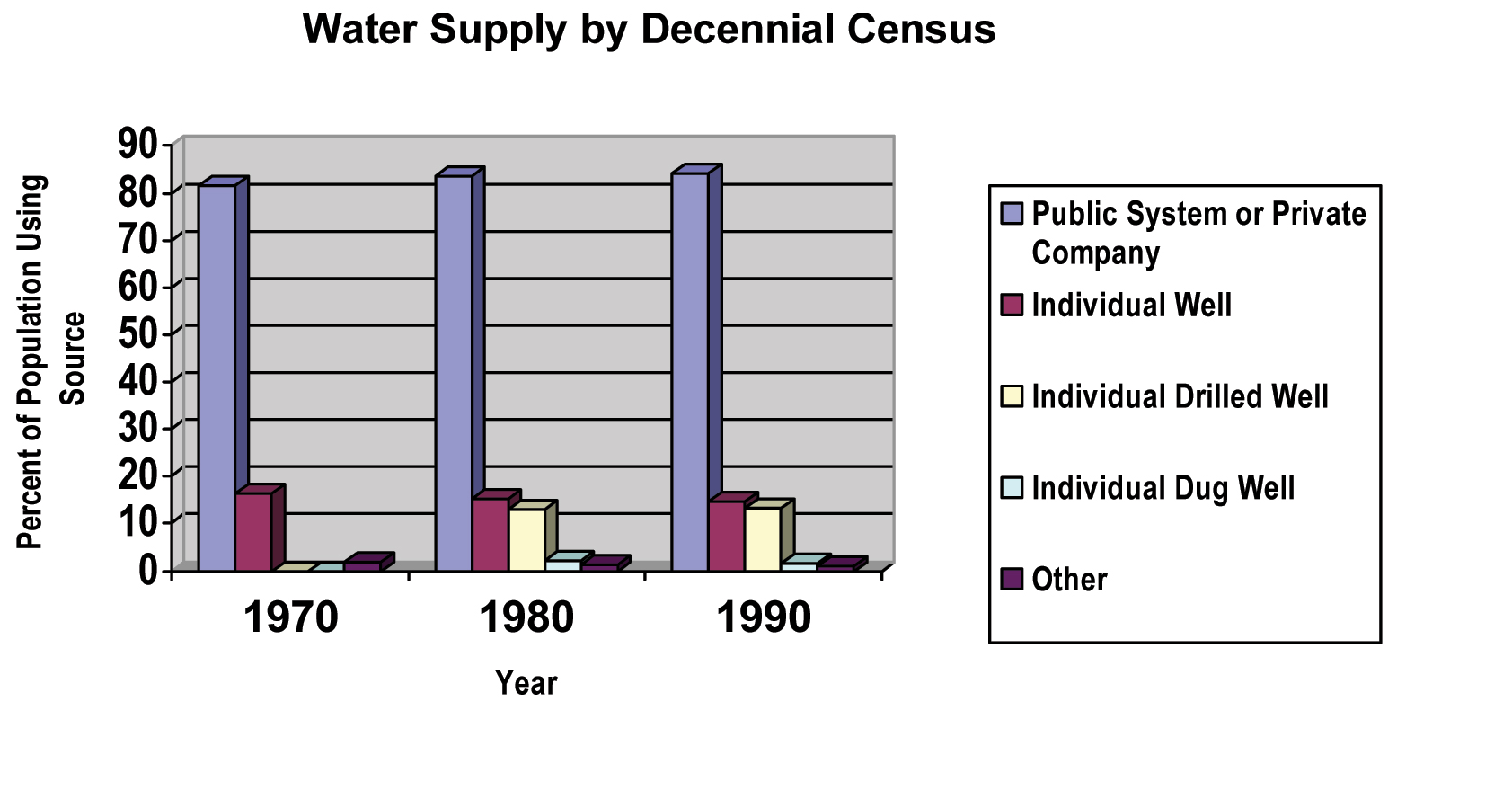
Figure 8.1 shows the change in water supply source in the United States
from 1970 to 1990. According to the 2003 American Housing Survey, of the 105,843,000
homes in the United States, water is provided to 92,324,000 (87.2%) by a public
or private business; 13,097,000 (12.4%) have a well (11,276,000 drilled, 919,000
dug, and 902,000 not reported) [2].
The primary sources of drinking water are groundwater and surface water. In addition, precipitation (rain and snow) can be collected and contained. The initial quality of the water depends on the source. Surface water (lakes, reservoirs, streams, and rivers), the drinking water source for approximately 50% of our population, is generally of poor quality and requires extensive treatment. Groundwater, the source for the other approximately 50% of our population, is of better quality. However, it still may be contaminated by agricultural runoff or surface and subsurface disposal of liquid waste, including leachate from solid waste landfills. Other sources, such as spring water and rain water, are of varying levels of quality, but each can be developed and treated to render it potable.
Most water systems consist of a water source (such as a well, spring, or lake), some type of tank for storage, and a system of pipes for distribution. Means to treat the water to remove harmful bacteria or chemicals may also be required. The system can be as simple as a well, a pump, and a pressure tank to serve a single home. It may be a complex system, with elaborate treatment processes, multiple storage tanks, and a large distribution system serving thousands of homes. Regardless of system size, the basic principles to assure the safety and potability of water are common to all systems. Large-scale water supply systems tend to rely on surface water resources, and smaller water systems tend to use groundwater.
Groundwater is pumped from wells drilled into aquifers. Aquifers are geologic formations where water pools, often deep in the ground. Some aquifers are actually higher than the surrounding ground surface, which can result in flowing springs or artesian wells. Artesian wells are often drilled; once the aquifer is penetrated, the water flows onto the surface of the ground because of the hydrologic pressure from the aquifer.
The Safe Drinking Water Act (SDWA) defines a public water system as one that provides piped water to at least 25 persons or 15 service connections for at least 60 days per year. Such systems may be owned by homeowner associations, investor-owned water companies, local governments, and others. Water not from a public water supply, and which serves one or only a few homes, is called a private supply. Private water supplies are, for the most part, unregulated. Community water systems are public systems that serve people year-round in their homes. The U.S. Environmental Protection Agency (EPA) also regulates other kinds of public water systems—such as those at schools, factories, campgrounds, or restaurants—that have their own water supply.
The quantity of water in an aquifer and the water produced by a well depend on the nature of the rock, sand, or soil in the aquifer where the well withdraws water. Drinking water wells may be shallow (50 feet or less) or deep (more than 1,000 feet).
On average, our society uses almost 100 gallons of drinking water per person per day. Traditionally, water use rates are described in units of gallons per capita per day (gallons used by one person in 1 day). Of the drinking water supplied by public water systems, only a small portion is actually used for drinking. Residential water consumers use most drinking water for other purposes, such as toilet flushing, bathing, cooking, cleaning, and lawn watering.
The amount of water we use in our homes varies during the day:
Source Location
The location of any source of water under consideration as a potable supply, whether individual or community, should be carefully evaluated for potential sources of contamination. As a general practice, the maximum distance that economics, land ownership, geology, and topography will allow should separate a water source from potential contamination sources. Table_8.1 details some of the sources of contamination and gives minimum distances recommended by EPA to separate pollution sources from the water source.
Water withdrawn directly from rivers, lakes, or reservoirs cannot be assumed to be clean enough for human consumption unless it receives treatment. Water pumped from underground aquifers will require some level of treatment. Believing surface water or soil-filtered water has purified itself is dangerous and unjustified. Clear water is not necessarily safe water. To assess the level of treatment a water source requires, follow these steps:
Well Construction
Many smaller communities obtain drinking water solely from underground aquifers. In addition, according to the last census with data on water supply systems, 15% of people in the United States are on individual water supply systems. In some sections of the country, there may be a choice of individual water supply sources that will supply water throughout the year. Some areas of the country may be limited to one source. The various sources of water include drilled wells, driven wells, jetted wells, dug wells, bored wells, springs, and cisterns. Table_8.2 provides a more detailed description of some of these wells.
Regardless of the choice for a water supply source, special safety precautions must be taken to assure the potability of the water. Drainage should be away from a well. The casings of the well should be sealed with grout or some other mastic material to ensure that surface water does not seep along the well casing to the water source. In Figure 8.2, the concrete grout has been reinforced with steel and a drain away from the casing has been provided to assist in protecting this water source. Additionally, research suggests that a minimum of 10 feet of soil is essential to filter unwanted biologic organisms from the water source.
However, if the area of well construction has any sources of chemical contamination nearby, the local public health authority should be contacted. In areas with karst topography (areas characterized by a limestone landscape with caves, fissures, and underground streams), wells of any type are a health risk because of the long distances that both chemical and biologic contaminants can travel.
When determining where a water well is to be located, several factors should be considered:
Sanitary Design and Construction
Whenever a water-bearing formation is penetrated (as in well construction), a direct route of possible water contamination exists unless satisfactory precautions are taken. Wells should be provided with casing or pipe to an adequate depth to prevent caving and to permit sealing of the earth formation to the casing with watertight cement grout or bentonite clay, from a point just below the surface to as deep as necessary to prevent entry of contaminated water.
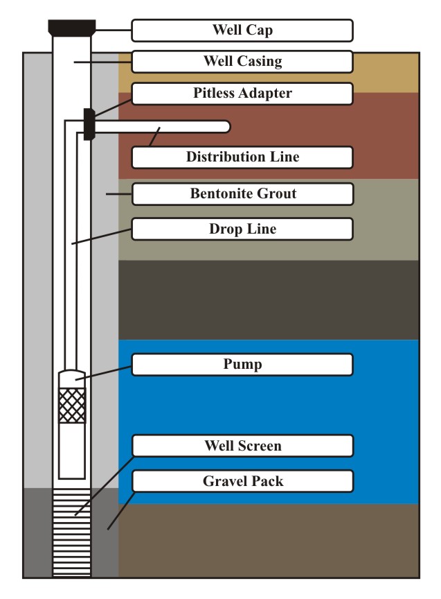
Once construction of the well is completed, the top of the well casing should be covered with a sanitary seal, an approved well cap, or a pump mounting that completely covers the well opening (Figure 8.3). If pumping at the design rate causes drawdown in the well, a vent through a tapped opening should be provided. The upper end of the vent pipe should be turned downward and suitably screened to prevent the entry of insects and foreign matter.
Pump Selection
A variety of pump types and sizes exist to meet the needs of individual or community water systems. Some of the factors to be considered in selecting a pump for a specific application are well depth, system design pressure, demand rate in gallons per minute, availability of power, and economics.
Dug and Drilled Wells
Dug wells (Figures 8.4 and 8.5) were one of the most common types of wells for individual water supply in the United States before the 1950s. They were often constructed with one person digging the hole with a shovel and another pulling the dirt from the hole with a rope, pulley, and bucket. Of course, this required a hole of rather large circumference, with the size increasing the potential for leakage from the surface. The dug well also was traditionally quite shallow, often less than 25 feet, which often resulted in the water source being contaminated by surface water as it ran through cracks and crevices in the ground to the aquifer. Dug wells provide potable water only if they are properly located and the water source is free of biologic and chemical contamination. The general rule is, the deeper the well, the more likely the aquifer is to be free of contaminants, as long as surface water does not leak into the well without sufficient soil filtration.
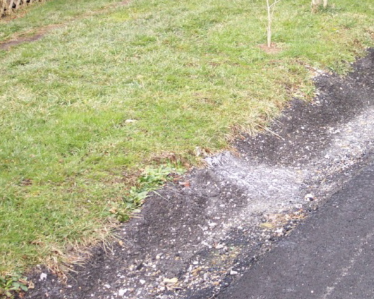
Two basic processes are used to remediate dug wells. One is to dig around the well to a depth of 10 feet and install a solid slab with a hole in it to accommodate a well casing and an appropriate seal (Figures 8.4 and 8.5). The dirt is then backfilled over the slab to the surface, and the casing is equipped with a vent and second seal, similar to a drilled well, as shown in Figure 8.6. This results in a considerable reduction in the area of the casing that needs to be protected. Experience has shown that the disturbed dirt used for backfilling over the buried slab will continue to release bacteria into the well for a short time after modification. Most experts in well modification suggest installing a chlorination system on all dug wells to disinfect the water because of their shallow depth and possible biologic impurity during changing drainage and weather conditions above ground. Figure 8.7 shows a dug well near the front porch of a house and within 5 feet of a drainage ditch and 6 feet of a rural road. This well is likely to be contaminated with the pesticide used to termite-proof the home and from whatever runs off the nearby road and drainage ditch. The well shown is about 15 feet deep. The brick structure around the well holds the centrifugal pump and a heater to keep the water from freezing. Although dangerous to drink from, this well is typical of dug wells used in rural areas of the United States for drinking water.
Samples should not be taken from such wells because they instill a false sense of security if they are negative for both chemicals and biologic organisms. The quality of the water in such wells can change in just a few hours through infiltration of drainage water. Figure 8.8 shows the septic tank discharge in the drainage ditch 5 feet upstream of the dug well in Figure 8.7. This potential combination of drinking water and waste disposal presents an extreme risk to the people serviced by the dug well. Sampling is not the answer; the water source should be changed under the supervision of qualified environmental health professionals.
Figure 8.9 shows a drilled well. On the left side of the picture is the corner of the porch of the home. The well appears not to have a sanitary well seal and is likely open to the air and will accept contaminants into the casing. Because the well is so close to the house, the casing is open, and the land slopes toward the well, it is a major candidate for contamination and not a safe water source.
Springs
Another source of water for individual water supply is natural springs. A spring is groundwater that reaches the surface because of the natural contours of the land.
Springs are common in rolling hillside and mountain areas. Some provide an ample supply of water, but most provide water only seasonally. Without proper precautions, the water may be biologically or chemically contaminated and not considered potable.
To obtain satisfactory (potable) water from a spring, it is necessary to
Cisterns
A cistern is a watertight, traditionally underground reservoir that is filled with rainwater draining from the roof of a building. Cisterns will not provide an ample supply of water for any extended period of time, unless the amount of water used is severely restricted. Because the water is coming off the roof, a pipe is generally installed to allow redirection of the first few minutes of rainwater until the water flows clear. Disinfection is, nevertheless, of utmost importance. Diverting the first flow of water does not assure safe, non-polluted water because chemicals and biologic waste from birds and other animals can migrate from catchment surfaces and from windblown sources. In addition, rainwater has a low pH, which can corrode plumbing pipes and fixtures if not treated.
Disinfection of Water Supplies
Water supplies can be disinfected by a variety of methods including chlorination, ozonation, ultraviolet radiation, heat, and iodination. The advantages and disadvantages of each method are noted in Table 8.3.
The understanding of certain terms is necessary in talking about chlorination. Table_8.4 is a chlorination guide for specific water conditions.
Chlorine is the most commonly used water disinfectant. It is available in liquid, powder, gas, and tablet form. Chlorine gas is often used for municipal water disinfection, but can be hazardous if mishandled. Recommended liquid, powder, and tablet forms of chlorine include the following:
On small systems or individual wells, a high-chlorine carrier solution is mixed in a tank in the pump house and pumped by the chlorinator into the system. Table_8.5 shows how to make a 200-ppm carrier solution. By using 200 ppm, only small quantities of this carrier have to be added. Depending on the system, other stock solutions may be needed to better use existing chemical feed equipment.
Routine Water Chlorination (Simple)
Most chlorinated public water supplies use routine water chlorination. Enough chlorine is added to the water to meet the chlorine demand, plus enough extra to supply 0.2 to 0.5 ppm of free chlorine when checked after 20 minutes.
Simple chlorination may not be enough to kill certain viruses. Chlorine as a disinfectant increases in effectiveness as the chlorine residual is increased and as the contact time is increased.
Chlorine solutions should be mixed and chlorinators adjusted according to the manufacturer’s instructions. Chlorine solutions deteriorate gradually when standing. Fresh solutions must be prepared as necessary to maintain the required chlorine residual. Chlorine residual should be tested at least once a week to assure effective equipment operation and solution strengths.
A dated record should be kept of solution preparation, type, proportion of chlorine used, and residual-test results. Sensing devices are available that will automatically shut off the pump and activate a warning bell or light when the chlorinator needs servicing.
Well Water Shock Chlorination
Shock chlorination is used to control iron and sulfate-reducing bacteria and to eliminate fecal coliform bacteria in a water system. To be effective, shock chlorination must disinfect the following: the entire well depth, the formation around the bottom of the well, the pressure system, water treatment equipment, and the distribution system. To accomplish this, a large volume of super-chlorinated water is siphoned down the well to displace the water in the well and some of the water in the formation around the well. Check specifications on the water treatment equipment to ensure appropriate protection of the equipment.
With shock chlorination, the entire system—from the water-bearing formation through the well-bore and the distribution system—is exposed to water that has a concentration of chlorine strong enough to kill iron and sulfate-reducing bacteria. The shock chlorination process is complex and tedious. Exact procedures and concentrations of chlorine for effective shock treatment are available [6,7].
Backflow, Back-siphonage, and Other Water Quality Problems
In addition to contamination at its source, water can become contaminated with biologic materials and toxic construction or unsuitable joint materials as it flows through the water distribution system in the home. Water flowing backwards (backflow) in the pipes sucks materials back (back-siphonage) into the water distribution system, creating equally hazardous conditions. Other water quality problems relate to hardness, dissolved iron and iron bacteria, acidity, turbidity, color, odor, and taste.
Backflow
Backflow is any unwanted flow of nonpotable water into a potable water system. The direction of flow is the reverse of that intended for the system. Backflow may be caused by numerous factors and conditions. For example, the reverse pressure gradient may be a result of either a loss of pressure in the supply main (back-siphonage) or the flow from a pressurized system through an unprotected cross-connection (back-pressure). A reverse flow in a distribution main or in a customer’s system can be created by a change of system pressure wherein the pressure at the supply point becomes lower than the pressure at the point of use. When this happens, the water at the point of use will be siphoned back into the system, potentially polluting or contaminating it. It is also possible that contaminated or polluted water could continue to backflow into the public distribution system. The point at which nonpotable water comes in contact with potable water is called a cross-connection.
Examples of backflow causes include supplemental supplies, such as a standby fire protection tank; fire pumps; chemical feed pumps that overpower the potable water system pressure; and sprinkler systems.
Back-Siphonage
Back-siphonage is a siphon action in an undesirable or reverse direction. When there is a direct or indirect connection between a potable water supply and water of questionable quality due to poor plumbing design or installation, there is always a possibility that the public water supply may become contaminated. Some examples of common plumbing defects are
Other Water Quality Problems
Water not only has to be safe to drink; it should also be aesthetically pleasing. Various water conditions affect water quality. Table_8.6 describes symptoms, causes, measurements, and how to correct these problems.
Protecting the Groundwater Supply
Follow these tips to help protect the quality of groundwater supplies:
References
Additional Sources of Information
American Water Works Association. Available from URL:
http://www.awwa.org.
Drexel University: Drinking water outbreaks. Available from URL:
http://water.sesep.drexel.edu/outbreaks/.
US Environmental Protection Agency: Ground water and drinking water. Available from
URL: http://www.epa.gov/safewater.
Table 8.1. Recommended Minimum Distance Between Well and Pollution Sources (Horizontal Distance) [1]
|
Pollution Source |
Minimum Surface Distance from Well |
|
Septic tank |
50 feet |
|
Livestock yard silos |
50
feet |
|
Petroleum tanks |
100 feet |
|
Manure stacks |
250 feet |
Table 8.2. Types of Wells for Accessing Groundwater, Well Depths, and Diameters
|
Type of Well |
Depth, in Feet |
Diameter |
Suitable Geologic Formations |
|
Dug |
0–50 |
3 to 20 feet |
Suitable in clay, silt, sand, gravel, and soft fractured limestone |
|
Bored |
0–100 |
2 to 30 inches |
Clay, silt, sand, gravel, boulders less than well diameter, soft sandstone, and fractured limestone |
|
Driven |
0–50 |
1.25 to 2 inches |
Clay, sand, silt, fine gravel, and thin layers of sandstone |
|
Drilled (rotary type) |
0–1,000 |
4 to 24 inches |
Same as above with percussion type drilling |
Table 8.3. Disinfection Methods
|
Disinfection Method |
Advantages |
Disadvantages |
|
Boiling |
Readily accessible Well suited for emergencies Removes volatile organic compounds from water Effective even on Giardia and Cryptosporidium |
Requires a great deal of heat Takes time to boil and cool Water tastes stale Typically limited capacity |
|
Chlorine |
Provides residual treatment Residual easy to test and measure Readily available; reasonable cost Low electrical requirement Useful for multiple water problems Can treat large volumes of water |
Requires contact time of 30 minutes Turbidity reduces effectiveness Gives water a chlorine taste May form disinfection by‑products Does not kill Giardia or Cryptosporidium Requires careful handling and storage |
|
Ultraviolet light |
Does not change taste of water Leaves no discernable odor Kills bacteria almost immediately Compact and easy to use |
High electrical requirement Provides no residual treatment Requires pretreatment if turbid Requires new lamp annually |
|
Iodine |
Does not require electricity Requires little maintenance Provides residual treatment Residual easy to measure |
Health side effects undetermined Affected by water temperature Gives water an iodine taste |
| Ozone |
Is a more powerful disinfectant than chlorine Does not change taste of water Leaves no discernable odor |
Ozone gas is unstable and must be generated at point of use |
Table 8.4. Chlorination Guide for Specific Water Conditions
|
Chlorination Treatment for |
Typical Dosage Rates |
|
Algae |
3 to 5 ppm |
|
Bacteria |
3 to 5 ppm |
|
Biologic oxygen demand reduction |
10 parts per million |
|
Color (removal) |
Dosage depends on type and extent of color removal desired; may vary from 1 to 500 ppm dosage rate |
|
Cyanide |
|
|
Reduction to cyanate |
2 times cyanide content |
|
Complete destruction |
8.5 times cyanide content |
|
Hydrogen sulfide |
|
|
Taste and odor control |
2 times hydrogen sulfide content |
|
Destruction |
8.4 times hydrogen sulfide content |
|
Iron bacteria |
1 to 10 ppm, varying with amount of bacteria to control |
|
Iron precipitation |
64 times iron content |
|
Manganese precipitation |
1 to 3 times manganese content |
|
Odor |
1 to 3 ppm |
|
Taste |
1 to 3 ppm |
|
ppm: parts per million |
|
Table 8.5. Preparing a 200-ppm Chlorine Solution
|
Carrier Solution |
Amount of Chlorine per 100 Gallons (380 Liters)
|
|
5% chlorine bleach |
3 pints |
|
12%–17% chlorine solution |
1 pint |
|
25%–30% chlorine powder |
⅔ pound |
|
65%–75% chlorine powder |
¼ pound |
Table 8.6. Analyzing and Correcting Water Quality Problems [8]
|
Symptoms |
Probable Cause |
Measurement |
Corrective Action |
|
Hardness – Sticky curd forms when soap is added to water – Causes bathtub ring – Requires more soap – Glassware appears streaked, scale forms in pipes |
Calcium and magnesium in the water, compounded with biocarbonates, sulfates or chlorides. |
Hardness test kits, which measure in grains per gallon (gpg) or parts per million (ppm). 1 gpg = 17.1 ppm 50 ppm is soft water; 50 to 100 ppm is moderately hard water; 100 to 200 ppm is hard water; 200 to 300 ppm is very hard; over 300 ppm is extremely hard |
If hardness creates problems, a sodium zeolite ion exchange water softener or a reverse osmosis unit can be used. |
|
Dissolved iron – Red stains (red water) on clothes and plumbing fixtures – Corrosion of steel pipes – Metallic taste – Clear water just drawn begins to form red particles that settle to the bottom |
Iron, from geologic formations that groundwater passes through. Water, an excellent solvent, ionizes iron and holds it in solution.
Iron is common in soft water and when water hardness is above 175 ppm. |
Atomic absorption (AA) units or numerous colormetric test kits measure iron in ppm. Any measurement above 0.3 ppm will cause problems. |
To treat soft water that contains no iron but picks it up in distribution lines, add calcium to the water with calcite (limestone) units. To treat hard water containing iron ions, install a sodium zeolite ion exchange unit. To treat soft water containing iron, carbon dioxide must be neutralized, followed by a manganese zeolite unit. |
|
Iron bacteria (red slime appears in toilet) |
Caused by bacteria that act in the presence of iron. |
Check under toilet tank cover for slippery jelly-like coating. |
Kill bacteria by superchlorinating pump and piping system. |
|
Brownish – Fixture stains black – Fabric stains black – Bitter coffee and tea |
Manganese is present usually along with iron. |
Colormetric tests for manganese (concentrations above 0.05 mg/L cause problems). |
Same methods as for iron. |
|
Acidity (corrosion of copper and steel in pumps, fixtures, piping and tanks) |
Carbon dioxide forms carbonic acid. Water may contain H2SO4, HCl, or nitric acid, but unlikely. |
Colormetric field titrametric tests for acidity, pH and carbon dioxide (pH is determined at the titration end point). A pH below 6.5 causes corrosion. Carbon dioxide should be less that 10 mg/L or less than 5 mg/L if alkalinity is less than 100 ppm. |
Soda ash solution is fed into the well or suction line of a pump. May be fed along with chlorine solution. Limestone chips (calcite) neutralize the water by increasing its alkalinity and hardness. |
|
Odors and tastes
– Bitter taste
– Rotten egg odor – Salty taste – Flat, soda taste – Salty taste – Chlorine odor/taste
|
Very high mineral content Sulfate-reducing bacteria, hydrogen sulfide High chloride levels Bicarbonates High total dissolved solids (TDS) High levels of di- or trichloramines in water
|
Excess iron, manganese, sulfate
Sulfate levels above 250 mg/L or any trace of hydrogen sulfide causes problem. Problems at levels >250 mg/L Carbonate hardness test TDS levels above 500 mg/L may cause problems. Check pH.
|
Methods mentioned above
Chlorinator and filter
Reverse osmosis unit Aeration unit Sand filter Activated charcoal filter
|
| Turbidity (cloudy water) | Silt, sediment, large number of microorganisms or organic material | Nephelometric turbidity units (NTUs) using laboratory spectrophotometers. (Less than 5 NTUs is best, >10 not acceptable.) | Fine filtering with sand filter or diatomaceous earth filter. For ponds, coagulation and sedimentation are needed. |
| Blue stain on porcelain fixtures | Corrosion of copper pipes and fixtures due to low pH, hardness, and alkalinity | Langelier index determines proper balance of pH, hardness, and alkalinity. | Methods mentioned above to adjust pH, hardness, and alkalinity. |
| Lead contamination | Leaching from lead service lines, solder, or brass or lead fittings | 15 parts per billion |
Adjust pH Filtration Chemical treatment
|
Centers for Disease Control and Prevention, 1600 Clifton Rd, Atlanta, GA 30333, U.S.A
Tel: (404) 639-3311 • CDC Contact Center: 800-CDC-INFO • 888-232-6348 (TTY)