|
Chapter 22A
Examination of Containers for Integrity
I. Examination of Metal Containers for Integrity
![]()
The quality of a food container is determined by its ability to protect the product it contains from chemical deterioration or microbiological spoilage. Good double and side seams are essential to a good hermetic seal, particularly at the cross-over (juncture); however, the performance of a can is also affected by many other factors. Spoilage within the can may be caused by leakage, underprocessing, or elevated storage temperatures. Leaker spoilage occurs mainly from seam defects and mechanical damage. Improper pressure control during retorting and cooling operations may stress the seam, resulting in poor seam integrity and subsequent leaker spoilage. However, the rate of container defects that might result in food spoilage is usually low.
The suitability of the particular food to be preserved also affects the performance of the container. Hydrogen swells and sulfide stains caused by chemical corrosion sometimes occur. In addition, prolonged storage of cans at elevated temperatures promotes corrosion and may result in perforation. Improper retorting operations, such as rapid pressure changes, may cause can deformation and damage seam integrity. Postprocess contamination by nonchlorinated cooling water or excessive buildup of bacteria in can-handling equipment may also cause spoilage, and abusive handling of containers may result in leaker spoilage.
Although the incidence of spoilage in canned foods is low, it is necessary to know how to proceed with the investigation of the integrity of the can when spoilage does occur. This chapter presents methods for seam examination and leakage detection.
Container examinations associated with food spoilage are usually accompanied by pH determination of the product, gas analysis of can headspace, and microbiological testing of the product (see Chapter 21). Analytical results that depart from normal patterns may indicate changes within the container and help to pinpoint the cause of spoilage.
The double seam (Fig. 1) consists of 5 thicknesses of plate (7 thicknesses at the juncture of end and side seam for 3-piece soldered cans, and 6.3-6.4 thicknesses at the juncture for welded cans) interlocked or folded and pressed firmly together, plus a thin layer of sealing compound. It is formed in 2 rolling operations. The side seam is bonded by welding or with solder or adhesive cement. Side seams of soldered cans consist of 4 thicknesses of metal body plate, except at the laps or cross-over areas, which have 2 thicknesses of metal. Side seams of welded and cemented cans have 2, or parts of 2, thicknesses of metal body plate (1.3-1.4 times the metal plate thickness for welded cans). [NOTE: the use of lead solder to close the seams of food cans is rapidly being prohibited in many nations.] Welded 3-piece cans permit reduction of side seam thickness and double seam thickness at the cross-over. Drawn cans eliminate the side seam and bottom end seam, resulting in fewer areas that affect can integrity. Can ends (Fig. 2) are punched from sheets; edges of the ends are curled, and a sealing compound is applied and dried in the lining channel (curl and flat areas) of the can end. Once the lined can end is double seamed onto a can body, the sealing compound in this compressive seal fills the voids (spaces) between the folds of metal in the properly made double seam to form an abuse-resistant hermetic seal.

Figure 1. Double seam.

Figure 2. Can end profile.
Sample size required for product analysis and can examination depends on the type of spoilage and complexity of the problem. When the cause of spoilage is clear, 4-6 cans may be enough. In more complex cases, it may be necessary to examine 50 or more cans. An adequate number of normal (flat) cans should be taken from the same case or lot for examination.
Remove labels, assign subnumbers, if necessary, and separate code numbers. Use same coding or subnumber system for both product and container examinations. Before removing any product sample, perform complete external can examination, observing such defects as evidence of leakage, pinholes or rusting, dents, buckling, and general exterior conditions.
Classify each can as (a) flat, (b) flipper, (c) springer, (d) soft swell, or (e) hard swell according to criteria in Chapter 21, Table 1. Leakage tests and external double seam dimensions may not be valid when cans are buckled. However, these cans should be examined and then torn down and re-examined for seam defects that may have existed before buckling. If possible, set aside reserve cans representing the classifications noted. Refrigerate reserve cans to prevent bursting.
Examine cans classified as springers and soft and hard swells immediately. Do not incubate. Remove sample from uncoded end of can in a manner that will not disturb double seam, e.g., with bacteriological can opener (Fig. 3). If can end has been punctured as a result of gas sampling, bacteriological can opener may be used if puncture is in center of end. If puncture is not in center, remove end with a pair of metal cutters.
![]()
Figure 3. Bacteriological can opener.
Note condition of cans (exterior and interior) and quality of seams. Observe and feel for gross abnormalities, mechanical defects, perforations, rust spots, and dents. Perform pressure and/or vacuum tests to detect invisible microleaks either in double seams or side seams. Measure seam dimensions and perform teardown examination. Note condition of double seam formation and construction (by micrometer, seam scope, or seam projector). Chemical, instrumental, metallographic, and other techniques may be required.
Use hand as well as eye. A magnifying glass with proper illumination is helpful. Run thumb and forefinger around seam on inside (chuck wall) and outside of seam to locate any roughness, uneveness, or sharpness. Examine by sight and touch for the following defects that may result in can leakage (for definition of terms, see glossary at end of this chapter):
The microleak tests are not listed in their order of sensitivity, nor is it necessary to use them all. Each has its advantages and disadvantages, depending on the particular set of conditions. In some instances a test may be chosen as a personal preference. They are all presented to provide the analyst with all the procedures and available options. Make all external measurements of can double seams before any microleak testing. See section on double seam measurements.

Figure 4. Vacuum leak test apparatus (NFDA).
This test applies a vacuum to the can, which more closely duplicates the condition in the can when it contains product and is sealed. Proponents of this method feel that using a vacuum to detect leakage in a can designed to hold a vacuum is more effective than using pressure. The use of a vacuum may remove food particles from leakage paths in can seams; pressure may force particles more deeply into leakage paths.
Remove uncoded end of can with bacteriological can opener adjusted to cut out can end, leaving 1/4 inch border around outer edge. Empty and wash container with water and suitable detergent to remove food particles lodged in seam area. (Ultrasonic cleaner may be used to remove small food particles lodged in seam areas.) Add wetting agent plus water to depth of about 1 inch. Place Plexiglas plate with tubing attached and wetted rubber gasket on open end of container. Increase vacuum until gauge indicates vacuum of 15-25 inches. Swirl water in container to dissipate small bubbles produced by application of vacuum. Tilt container slowly to immerse all seam surfaces, letting light source focus through Plexiglas into can for better observation. Rotate tilted can so that all surfaces are observed and covered with water. Depending on size of hole, path of leakage, pressure differential, and surface tension of the test water, bubbles will appear smaller or larger and with lesser or greater frequency. Release vacuum by first closing main vacuum petcock and then opening intake petcock.

Figure 5. Mead Jar Test apparatus.
This nondestructive examination determines leakage paths of finished cans that have both ends double seamed. It is used primarily for vacuum- or nonvacuum-packed dried or semidried products. Deaerated water is preferred because, as vacuum is pulled on the jar, dissolved air in the water comes out of solution as bubbles, preventing a clear view of the container and any leakage bubbles. This test would rarely be used for items thermally processed in metal cans.
Place enough deaerated water into Mead jar to completely submerge test container. Put container in water and, if necessary, place device or weight on it to hold it under water. Place mesh protector around jar, and put Vaseline on rubber gasket on underside of top piece to act as sealant between gasket and lip of Mead jar. Place lid on top of jar and rotate it to improve seal. Attach rubber hose to vacuum line. Turn off air inlet stopcock and open vacuum line stopcock. Turn on vacuum and record vacuum reading on gauge if leakage or air bubbles emanate from container. Note location of leakage point. Turn up to full vacuum if no leakage is noted. Turn off vacuum and open air inlet valve to release vacuum. Take off lid, remove container, and mark leakage point.
CAUTION: Do not use defective or cracked Mead jars because of danger of collapsing them. Always put wire mesh protector in place before turning on vacuum. For a container to be classified as a leaker, a continuous stream of bubbles from a single point is necessary. Unless leakage is obvious, the can should be observed under test conditions for at least 30 s. Generally, a few bubbles will be seen when the vacuum is first applied because of air entrapment in the double seams. These should not be confused with leakage point bubbles.

Figure 6. Air pressure test apparatus.
For detection of container leakage caused by minute body pinholes and perforations, and/or defective side seams, air pressure testing is the most convenient and conclusive. It is also helpful for locating double seam leaks. During pressure testing, double seams may be distorted, producing false leakers or sealing off minute leakage paths. For this reason, the air pressure testing method should be used in conjunction with the fluorescein test or penetrant dye test to trace the actual leakage path through double seams.
Preparation of samples. Open filled cans at one end with bacteriological can opener so that double seam remains intact. Manufacturer's end is usually opened, but if enough samples are available, half the cans may be opened at packer's end. After removing contents, wash cans thoroughly. Wash containers of fatty or oily products with warm detergent and water, or boil them in detergent and water; use ultrasonic cleaner to remove all fat or oil trapped in the double seam. Dry cans at least 8 h at 100-120°F before pressure testing.
Pressure test. Fill foot tester with warm water (100-120°F) to about 2 inches from top. Set air pressure control valve at desired pressure level (20 lb for most sanitary cans). Seat open end of test can against rubber base plate, side seam up, and lower pressure bar against can with just enough pressure to hold can in place. Secure pressure bar in this position with 2 nuts so that adjustment is not necessary for testing additional cans of same size. Close exhaust gate valve and completely immerse can in tank by stepping on foot pedal. With can completely immersed, open pressurized gate valve, letting air flow into can. Hold can in this position long enough to detect any leakage points.
Leakage may be shown by steady stream of large bubbles or continued intermittent escape of very tiny bubbles. If leakage is present, close pressurized gate valve and exhaust can by opening exhaust gate valve. Release foot pressure and lift can out of water. Rotate can 180 against rubber base plate until new area of can is exposed, and repeat pressure testing operation. Mark location of any leaks noted during test for use as reference when cans are examined further. Do not exceed 30 psi because can may burst beyond this level.
After pressure testing, use fluorescein test to obtain additional information on presence of any leakage paths, or strip can seams for further examination if point of leakage is conclusively located.
During pressure testing operation, pay particular attention to cross-over areas and double seams on both ends of can. Also observe side seam area closely and scan bodies for pinholes or perforations. Use warm water during test. During drying, small leakage paths will be opened; these may be reclosed by contraction of the can during testing in cold water. (NOTE: The air pressure test must not be rushed. Very small leaks may take several seconds to show up, and then the only evidence may be the intermittent flow of very tiny bubbles.
Fluorescein dye testing has been used for many years to detect minute double seam, lap, and side seam leakage paths in all types of containers. The fluorescein test is especially useful for examining sanitary-style containers that are normally packed with some initial vacuum. Fluorescein dye can often be used to detect minute leakage paths on suspected cans that do not leak under the air pressure test. Fluorescein testing of most types of containers under vacuum simulates actual packed condition, i.e., with ends pulled inward.

Figure 7. Ultraviolet light for fluorescein dye test.
Fluorescein dye solution. Mix 100 ml triethylene glycol, 300 ml water, 15 g glycerine, 3 g wetting agent, such as Triton X-100 (R86), and 3 g sodium fluorescein, technical grade. (Zyglo dye solution ZL-4B is available from Magnaflux Corporation, Chicago, IL.)
Preparation of sample. Open filled cans at one end with bacteriological can opener so that double seam remains intact. Manufacturer's end is usually opened, but if enough samples are available, half the containers may be opened at packer's end. After removing contents, wash and dry containers thoroughly. Wash containers of fatty or oily products with hot detergent and water, or boil them in detergent and water to remove all fat or oil trapped in double seams. Use ultrasonic bath to remove small food particles lodged in seam areas.
Vacuum application (Fig. 8). Place opened end of emptied and dried container against vertically mounted rubber-faced plate connected to vacuum line. As a general rule, 15-20 inches of vacuum is used for most pressure-processed sanitary-style containers. For other container styles, maximum allowable vacuum to be used depends on panel resistance of bodies.
After container is mounted in place and vacuum drawn, apply fluorescein solution with a small brush or eyedropper to outside double seam and side seam areas. OR place can in dye bath to cover seam and/or score areas to be examined. Run test for 30 min to 2 h, depending on style of container being examined. Longer test period may be required to detect microleaks. If in doubt as to time needed to demonstrate leakage, remove containers every 30 min and check inside with UV light for presence of fluorescein. Since fluorescein solution runs off the mounted container, apply fresh solution at 15 min intervals.
Container examination. At end of vacuum test period, thoroughly remove fluorescein remaining on outside of containers with water; then wipe dry. Take special care not to splash any fluorescein into opened end of container. After cleaning excess solution from outside, strip the double seam and examine it under UV light to detect any fluorescein on the inside. Do not allow wet solution trapped in outside of double seam to creep inside container, thus giving false-positive results. Also, keep tools clean of fluorescein to prevent contamination during stripping. Examine containers immediately after vacuum testing, since dried fluorescein solution does not fluoresce (Fig. 8).

Figure 8. Application of vacuum for fluorescein dye test.
NOTE: Sample report forms for double seam examination (Chart 1) and for the complete container integrity examination (Chart 2) are included at the end of this chapter.

Figure 9. Materials for teardown and cross-section strip examination.
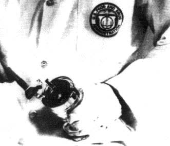
Figure 10. Removal of cover hook.
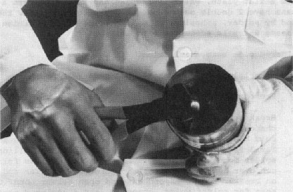
Figure 11. Removal of cover hook (alternative procedure).
Strip off cover hook to point where remaining end metal has not been removed (about 1/2 inch from second metal strip). Measure body and cover hooks. Grade cover hook for tightness by examining and evaluating wrinkles. Examine cross-over area of 3-piece soldered cans for wrinkles and for crawled laps (body hook of one side of cross-over drops down or crawls below bottom of other side) in soldered cans.
Observe double seams for plate fractures. Inspect interior of body wall in double seam area for well-defined continuous impression around circumference of can. This is referred to as pressure ridge and is one indication of seam tightness, although pressure ridge may or may not be present in a good seam. Tape cover hooks and coded end to can so that they may be identified as belonging to the can in question. If cover hooks are still attached, bend them inward inside the can body to prevent cut injury.
As mentioned previously, measure countersinks while ends of can are still intact. On swelled cans these measurement are seldom meaningful because of possible distention caused by swelling. However, measurements that indicate deep countersinks are useful because they represent the condition as is.
NOTE: Food products are packed in 2 basic types of cans: the 2- and 3-piece cans. The 2-piece can has a drawn body, no side seam, and only one double seamed end, thus the term 2-piece. Side seam and lap examination are not applicable to these cans. Three-piece can bodies are made from a flat plate, which is rounded and seamed to form a cylinder. These cans have 2 double seam ends, thus the term 3-piece. The side seam is sealed by solder, adhesive, or welding, and is in addition to the double seam, which is susceptible to leakage.
Break open and observe both laps. Note solder voids and channels, and discolored and stained solder. Identify hot and cold breaks in solder. Observe flange area of the lap closely for defects. Examine side seam construction, pulling apart solder bond with side seam breaker (Fig. 12) as follows. Place can over body horse of appropriate can diameter and pull down on breaker arm to expand can and open solder bond. Observe side seam for solder voids, channels, and discolored areas.

Figure 12. Side seam breaker.
Examine laps for heavy solder, evidenced by excessive solder adjacent to lap inside and outside can, or on body hook, causing severely crawled lap or cutover. Break open lap to see if excessive solder is still present in lap.
The portion of the cover hook that intersects the side seam is called the juncture area and is about 3/8 inch wide. In an ideally made 3-piece can, length of cover hook is not reduced at the juncture, even though cover hook is depressed at this point. In most commercial 3-piece cans, length of the cover hook is reduced at the side seam in varying degrees. The shortening of the cover hook at the side seam is caused by the 2 additional thicknesses of body flange at the side seam. These additional layers of metal prevent the cover hook from being tucked up under the body hook as it is under the body hook away from the side seam.
A good juncture with sufficiently long cover and body hooks is essential. Without a good juncture, the overlap at the side seam may be critically short, making the can less abuse-resistant. As with the tightness rating, which is based on the wrinkle-free metal of the hook length, the juncture rating is based on the amount of droop-free metal for the existing hook length away from the juncture. Because the cover hook is frequently shorter at the juncture in the form of a droop, the juncture is rated on a percentage scale, starting at 100% (ideal) and decreasing in 25% increments. If the cover hook in the juncture is even with the rest of the cover hook, it is rated 100%. If the cover hook reduction at the juncture is about 1/4 the length of the cover hook, the juncture is rated 75%. If the cover hook at the juncture is 1/2 the length of the rest of the cover hook, the juncture is rated 50%. Similarly, if the cover hook length at the juncture is only 1/4 the length of the rest of the cover hook, it is rated 25%.
A severe condition of crawled laps results in an area of little overlap at the cross-over, creating a possible leakage point. This condition is usually, but not always, accompanied by an external droop at the cross-over. Cover hooks made with double cold reduced (2 CR) ends may look wrinkled, but these wrinkles may be reverse wrinkles, which do not indicate a loose seam. Compound wrinkles do not give wavy cut edges to the cover hook and are not used to establish tightness ratings. Discolored or stained solder may indicate previous leakage through the lap. It is not necessary to have a solderless channel for leakage to occur at the lap. This can happen as a result of either a hot break or a cold break in the solder. Both of these conditions are conducive to container leakage. A hot break is identified by solder that appears relatively smooth; it occurs in the soldering operation during manufacture when the lap opens up before the solder solidifies completely. A cold break gives the solder a round, mottled appearance; if leakage has occurred at this point, the area shows a dark discoloration. Cold breaks may occur at almost any time after the solder has hardened. They are difficult for manufacturing plants to detect because they usually occur after manufacturing. Cold breaks are usually caused by weak soldering bonds or poor manufacturing techniques.
In general, if pressure testing shows leakage at the cross-over, if the fluorescein test indicates a path through the flange area, and if no other double seam or lap defects are found at the cross-over, the most likely cause of leakage is a solder break at the flange area of the lap. It is also possible to have no solder at this area. This defect is easier to detect visually than the solder break. The leakage path may be confirmed by a fluorescein path or by stained or darkened solder. A condition known as an "island" is often observed in the side seam. An island is an isolated area in the side seam fold that is void of solder, but without a connecting solderless path, or break, leading to the outside of the can. This condition is not necessarily associated with leakage, but does indicate a weak side seam.
Examine the flange area for flange cracks, the weld for blow holes or weld splashes, and the lap area for fishtail. NOTE: A fishtail is a piece of metal extending beyond the flange at the lap area that might cause double seam difficulty. Any of the above defects in the weld may result in leakage. However, this should be supported by a valid leak test.
Use a micrometer especially made for measuring double seams and reading to nearest 0.001 inch. Be sure to adjust micrometer properly. When micrometer is set at zero position, zero graduation on movable barrel should match exactly with index line on stationary member. If zero adjustment is more than 1/2 space from index line at this setting, adjust it.
Make seam measurements on round cans, at minimum of 3 points about 120 apart, around circumference of can, beginning about an inch to one side of cross-over (or at least 1/2 inch away from cross-over).
Obtain the 5 required measurements: seam thickness; seam width (length, height); body hook length; cover hook length; and tightness (observation for wrinkle).
The 2 optional measurements are countersink depth and overlap, calculated by the following formula:
where CH is cover hook length, BH is body hook length, T is cover plate thickness, and W is seam width (height, length). Grade tightness (wrinkle) (2) of double seam by examining cover hook wrinkle according to percentages illustrated in Figs. 13 and 14. Drawing shows cover hook with 0-100% tightness, with wrinkle number shown below it. Tightness can also be indicated by flatness of cover hook; that is, cover hook should not appear round. Make this observation on cover hook removed from seam that has been sectioned with seam saw (Fig. 15). This method is good verification for wrinkle method but should not be a substitute for it. Tightness may be expressed in terms of percentage of cover hook not included in wrinkle or by rating number equivalent to distance up cover hook. Both procedures are listed below. Percentage method is preferred.

Figure 13. Tightness (wrinkle) rating in percent.

Figure 14. Evaluation of tightness by flatness of the cover hook.
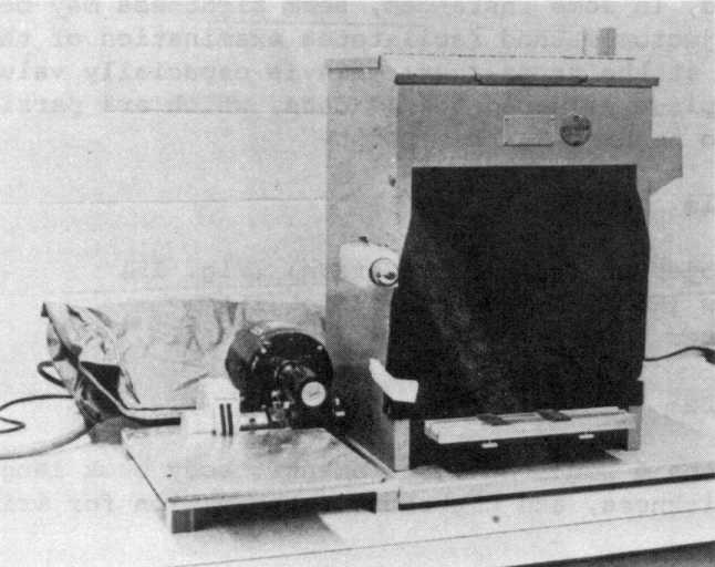
Figure 15. Waco Saw for sectioning, to left, and seam projector for examining cross sections of double seams, to right in photograph.
Tightness, expressed in terms of wrinkles: No. 0 - Smooth, no wrinkle No. 1 - Wrinkle up to 1/3 distance from edge
No. 2 - Wrinkle up to 1/2 distance from edge No. 3 - Wrinkle up to more than 1/2 distance from edge
Tightness ratings expressed in % of cover hook not included in the wrinkle (preferred method):
|
100 |
- |
Equivalent to No. 0 |
|
90 |
- |
Equivalent to between Nos. 0 and 1 |
|
70 |
- |
Equivalent to No. 1 |
|
50 |
- |
Equivalent to No. 2 |
|
<50 |
- |
Equivalent to No. 3 |
Rate the juncture as previously described. Measure free space to determine seam condition of 2-piece oblong and 2-piece oval cans, as follows:
FS = ST - (2BPT + 3CPT)
where ST is seam thickness, BPT is body plate thickness, and CPT is cover plate thickness. NOTE: Specifications are not yet well established.
As an alternative to the use of the micrometer, or as a verification, cross-sections of double seams may be examined visually with a seam projector. A section of the double seam is cut in the form of a metal strip that remains attached to the can body and that is then placed in the projector. From the image projected on the screen, the seam width, hook lengths, and overlap dimensions may be measured with a specially calibrated caliper. General seam formation and, in some instances, seam tightness may be observed. The seam projector method facilitates examination of the critical overlap area at the cross-over; this is especially valuable for examining 3-piece soldered No. 10 cans, which are particularly vulnerable to leakage at this point.
Obtain the 4 required measurements: body hook length, overlap, seam thickness, and tightness (observation for wrinkle). The 3 optional measurements are width (length, height), cover hook length, and countersink depth.
Measure each double seam characteristic at 2 different locations on each double seam, excluding the cross-over. Cut cross-sections through double seams with Waco seam saw. Polish cross-section surface with fine emery cloth to ensure bright surface that will project clear image on screen. Place polished section in clamp on side of projector, look into shadow box, and observe image. Bring calipers in instrument into position. Note any looseness, tightness, or other malformations. With calibrated calipers, carefully measure and record width, cover hook, body hook, and overlap on image. Repeat this procedure in all 4 different locations along double seam. To properly evaluate seam for degree of looseness, strip cover hook from can, and visually grade for wrinkle formation. Observe absence or discontinuities of sealing compound after cover hook is removed from double seam. Enter observations on Chart 2 (shown at end of this chapter). Sealing compound should form complete 360 circle around edge of lid.
Overlap percentage is a measure of both how well end hook and body hook overlap and how well hooks match each other in length. It is also a ratio of the existing distance between body hook and cover hook compared to the distance the hooks would lap for the given seam. Overlap percentage is measured directly when seam projector is used with nomograph placed on viewing screen (Fig. 16). Calculate percentage from seam length, body hook, cover hook, and body and end plate thicknesses.
Overlap, % = 100 x (BH + CH + EPT - W)/[W - (2EPT + BPT)]
where BH is body hook length, CH is cover hook length, EPT is end plate thickness, W is width (seam height, length), and BPT is body plate thickness. Use minimum value found for each measurement (maximum value for W), to approximate lowest possible overlap percentage. Overlap may also be measured in thousandth inches or millimeters with calibrated calipers, as above.

Figure 16. Nomograph for use with seam projector.
Open calipers as wide as possible and place nomograph card on screen. Position nomograph card so that image appears on it and reference lines of nomograph are parallel to hook images. Adjust position of nomograph to place zero line on side of body hook radius of image; then move it forward or backward until the 100 line is on inside of end hook radius. Now, move nomograph, keeping reference lines parallel to hooks and allowing no forward or backward motion, until zero line is at end of end hook; read nomograph at end of body hook. This value is percent overlap. Rate the juncture as previously described.
Sardines are packed predominantly in a shallow rectangular (or oblong) 405x301x014 2-piece (drawn) aluminum can, with a scored, pull-tab type lid (known as "quarter-pound" can; Fig. 17). A larger volume of fish is packed into an oval 607x403x108 2-piece (drawn) aluminum can (known as "pound oval"; Fig. 18). A 405 tin-plated steel can and a 405 drawn aluminum can, both without the scored pull-tab top, are also used. The longer western sardine (pilchard) is packed in oval and round cans in 1/4 and l-lb units. Examination of imported sardines for container integrity is much like that for round sanitary cans. This section covers areas that are evaluated differently and specific problems inherent in these cans.

Figure 17. Measurement point template. Double seam examination of a "quarter-pound" aluminum sardine can.
P1 -- Locus for seam cut and/or micrometer measuring point
P2 -- Cover hook (and body wall) section number, pertinent to examination for wrinkle and pressure ridge

Figure 18.
Measurement point template. Double seam examination of a "one-pound oval" aluminum sardine can.
P1 -- Locus for seam cut and/or micrometer measuring point
P2 -- Cover hook (and body wall) section number, pertinent to examination for wrinkle and pressure ridge
A major integrity problem with these cans is the formation of the so-called cover hook "droop," usually at or near one of the 4 corners of the can, with resulting short overlaps at the droop area. An additional factor is the degree of wrinkle at the corners. If this wrinkle is used to rate cover hook tightness, it often indicates a tightness rating below specifications established by most domestic can manufacturers. However, the remainder of the cover hook away from the corners will, at the same time, appear to have an acceptable tightness rating. The following procedures have been developed for the examination of the 405 and 607 drawn aluminum sardine cans.
Visual examination of cans is applicable for 405 and 607 drawn aluminum sardine cans. Be alert to such conditions as minute leakage of packing medium around scored area of lid, as well as base or attachment point of pull tab, on the 405 can. The primary gross closure defect associated with 405 containers has been cover hook droop, usually at or near one of the 4 corners. One cause of droop is product overhanging the can flange before seaming. Visually examine the area surrounding the droop for evidence of product trapped in the seam.
National Food Processors Association (NFPA) Vacuum Leak Test (19). Can examination (microleak detection, NFPA vacuum leak test), above, is also applicable for 405 and 607 sardine cans.
Fluorescein dye test. Use bacteriological cutter to remove portion of no-lid end. Check lids, score, and rivet area for evidence of leakage.
405x301x014 (quarter-pound) oblong can. The location for micrometer and/or seam projector measurement (i.e., standard for the round sanitary can) may be sufficient to adequately interpret the integrity of the 405 drawn aluminum sardine can. Figure 17 illustrates the template that was constructed as a guide for double seam examination of the 405 can. Four points, P1 to P4, were selected as locations for seam (projector and/or micrometer) measurements. The P2 location is stripped and examined for wrinkle and presence of pressure ridge. Length, thickness, body hook, and cover hook are generally measured at P3 location, and the data are recorded. With respect to examination for wrinkle and pressure ridge, firms that made seam scope measurements would either strip sections of the cover hook from between the measurement points or completely strip another can pulled along with the first.
607x403x108 (l-lb) oval can. Figure 18 illustrates template constructed as industry guide for double seam examination of the 607 can. Four points, P1 to P4, were selected as locations for seam micrometer and/or seam projector measurements. As with Fig. 17, P2 represents cover hook and body wall sections that are to be stripped and examined for tightness and presence of pressure ridge.
As specific points on both the 405 and 607 containers were indicated as potential problem areas, with respect to droop, overlap, and tightness, the 5 recommended points for measurement may be entered under the last column of Chart 1 to allow for easier identification of these points. However, the selection of the P1 location on both cans was designed to provide a general reference point (the 301 side closest to the pull-tab on the 405 can; the point on the 607 can closest to the embossed code) similar to the side seam on a 3-piece container. P3 and its 3 corresponding points along the straight section of the double seam on the 405 can generally reflect the measurement points used by industry. P2 and 3 other corner points and adjacent areas have indicated potential weakness with respect to droop, low overlap, and low tightness. Therefore, the data sheet shown in Chart 2 allows immediate comparison of data obtained on 2 sets of points. If the visual and microleak examinations indicate one particular weak area of the seam, double seam teardown could be performed in that particular area.
With a bacteriological can opener (Fig. 3), remove circular disk, about 1 to 1-1/2 inches in diameter, from center of bottom panel of container. Then, with metal cutters or tin snips, remove most of remainder of bottom, leaving about 1/2 inch border around outer edge of container. Empty and wash container with detergent and warm water; use a brush if necessary. Next, boil container in detergent and water to remove as much as possible of any product that may be trapped in the seam. Or place container in ultrasonic washer with detergent and wash at about 100-120°F for at least 2 h. In either case, dry the container in an oven at about 100-120°F for at least 2 h.
Add distilled water plus wetting agent to a depth that just covers entire lid area. Place Plexiglas with tubing attached and wetted rubber gasket on open bottom of container. Begin with initial vacuum of 5 inches, increasing gradually to maximum of 20-22 inches. Swirl water in container to dissipate small bubbles produced by application of vacuum. Tilt container slowly to immerse all seam surfaces and scored area of the 405 container, letting light source focus through Plexiglas into can.
Hermetically sealed food cans are tested in a chamber (Fig. 19) under either vacuum or pressure, by applying a predetermined amount of stress to cans. The can surface is viewed for fringes as the can ends deform in response to the applied stress. A hologram showing the image of fringes is recorded by a reflected laser beam of a subject illuminated by a portion of the laser beam. A hologram of cans within the test chamber is recorded on video tape and may also be exposed and developed in place with a liquid gate film holder. The pattern of fringes that occurs on the can surface indicates the relative size of the leak. To locate the leak, the stress applied to cans in the testing chamber is slowly varied, the seam area is photographically enlarged, and fringe control techniques are applied. Figure 20 is a Polaroid picture taken from a TV video monitor. The can on the left, which does not show fringes in the hologram, is the leaker.
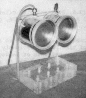
Figure 19. Test chamber.

Figure 20. Hologram showing the image of fringes.
Equipment for leak detection includes:
Flat cans are exposed to helium pressure in an enclosed tank for a specified period of time. Cans previously exposed to pressurized helium are observed for evidence of leakage: a swollen can is an indication of a leaker; a paneled can or a can with vacuum is usually not a leaker. Headspace gas is analyzed by gas chromatography to confirm the presence of helium. Cans with large amounts of internal air (e.g., dried or semidried products) are crushed by helium pressure and should not be tested by this procedure.
A swollen can is first depressurized, and, if necessary, a sample of the contents is removed for microbiological analysis. After resealing, the can is tested for a leak. Swollen cans may be sampled for headspace gas analysis by gas chromatography. The helium leak test detects holes as small as 1 m. Results are reported as percent helium in the headspace gas.

Figure 21. Gas chromatograph for use in helium leak test.
Gas chromatograph (Fig. 21) capable of separating and measuring
nitrogen, oxygen, hydrogen, helium, and carbon dioxide (Chapter 21)
Strip chart recorder or other readout system
Puncturing press (Chapter 21)
Helium exposure tank tested to 100 psi (American Society of Mechanical
Engineers paint tank, 10 gal) equipped with inlet and
outlet micro control valves
Pressurized helium tank with 2-stage regulator
Pressure regulator
Combination vacuum-pressure gauge for use on puncturing press Timer
and solenoid to automate release of helium from exposure tank
Helium gas standards
Cyanoacrylate glue
Can opener, bacteriological (Fig. 3)
Rubber disks, 2-3/8 x 1/8 inch
Calibration of gas chromatograph. For gas chromatographs equipped with side port loop (0.5 ml), inject 5.0 ml calibrated helium standards (suggested range 5, 15, 25, 50, and 75% helium). For instruments not equipped with side port loop, inject appropriate volume of standards. Use same volume for analysis of headspace gas samples. Plot percent helium vs helium peak height at attenuation used. Depending on quality of instrument, plot should approximate a linear or continuous curve.

Figure 22. Helium exposure tank.
Helium exposure tank (Fig. 22). Control the rate of introduction of helium into exposure tank and time that cans are exposed to helium pressure at 45 psi. Timer, solenoid, and microvalves with Vernier scales can facilitate procedure. Connect helium source to exposure tank. Turn timer on to close outlet solenoid valve. Adjust inlet and outlet microvalves to settings of 0.25 and 0.5, respectively, on Vernier scale. At these settings, it should take about 20 min to reach 45 psi in tank. Make minor adjustments if necessary. Adjust timer to expose cans to helium pressure at 45 psi for 30 min, in addition to time necessary to reach 45 psi.

Figure 23. Sealing an open can.
Sealing an open can (Fig. 23). A swollen can must be depressurized and resealed before exposure to helium. Release pressure by puncturing and, if necessary, cut hole 1.5 inches in diameter to remove sample for microbiological analysis as described in Chapter 21. Depress any high edges and roughen area around hole with emery cloth. Pool glue (cyanoacrylate) around hole and press rubber disk 2-3/8 inches in diameter (1/8 inch thick) into glue. Take care to remove any air bubbles. Place weight (400 ml beaker filled with water) on disk for at least 1 h to obtain effective seal before exposure to helium.
Collection and analysis of headspace gas. After exposure to helium, make visual observation of cans (Chapter 21, Table 1). Can piercing assembly is shown in Fig. 24. Before piercing can, close gauge valve and pull plunger on syringe to remove air from silicone tubing. Close syringe valve and expel air from syringe. Puncture can and open gauge valve to read vacuum or pressure. Turn gauge valve and syringe valve to release gas into syringe. If gas sample is >5.0 ml, withdraw only 5.0 ml and inject into side port of gas chromatograph. If gas sample is <5.0 ml, force collected gas back into can. Close syringe valve to retain gas in tubing and can. Use syringe to add 40 ml room air to can, and pump syringe twice to mix gas. Let syringe equilibrate to atmospheric pressure and record syringe volume. From this dilute gas, obtain sample for gas chromatograph. Divide percent helium measured by dilution factor to determine correct percent helium in headspace gas. Use the following formula:
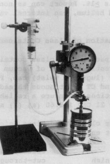
Figure 24. Can piercer and gas collection apparatus.
Dilution factor = (equilibrated syringe volume - 40 ml air + headspace volume)/(equilibrated syringe volume + headspace volume)
Example: (43 - 40 + 9)/(43 + 9) = 12/52 = 0.23 dilution factor % helium in can = % helium measured/dilution factor
Example: 5% helium/0.23 = 22% helium in can
Measure headspace volume by piercing a control can that still has vacuum. Measure both amount of vacuum (inches Hg) and volume of air pulled in from syringe.
Headspace volume = measured volume from syringe x 30 inches of mercury/measured vacuum in can in inches of mercury
Example: If 6 ml air was pulled into can and vacuum was 20 inches of mercury:
Headspace volume = 6 ml x 30 inches Hg/20 inches Hg = 9 ml
For performing additional work on the can, the collected gas may be stored in a capped syringe for a few hours without appreciable change in its composition.
Interpretation of results. Report can as leaker if, after exposure to pressurized helium, can internal pressure is 8 psi or helium is 1%. Report can as nonleaker if, after exposure to pressurized helium, can internal vacuum is 5 inches, or helium is <1%.
Hypertext Source: Bacteriological Analytical Manual, 8th Edition, Revision A, 1998. Chapter 22.
*Authors: Rong C. Lin, Paul H. King, and Melvin R. Johnston
Hypertext updated by bap/kwg/cjm 2001-OCT-24