 Translate
Oil and Gas Well Drilling and Servicing eTool
Home | Site Preparation | Drilling | Well Completion | Servicing | Plug and Abandon Well | General Safety and Health
Site Map | Glossary of Terms | Illustrated Glossary
Servicing Transporting Rig and Rigging Up


Fig. 1. Servicing rig
Transporting and rigging up the equipment is the first step in well servicing operations. After these steps, servicing activities commence.
Hazards may be related to the following:
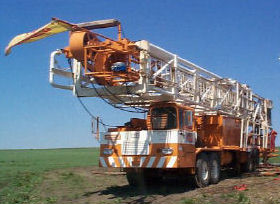
Fig. 2. Transporting rig
After the drilling rig is removed, the well site is cleaned and re-leveled for the service rig. A workover rig is driven or transported to the site and positioned at the well.
Potential Hazard:
- Working in unstable or slippery conditions on the lease road/drill site.
- Striking fixed objects such as power line poles.
- Contacting electrical service lines.
- Being involved in vehicular accidents.
- Getting caught between the rig and the wellhead.
- Being struck by a moving rig.
Possible Solutions:
- Inspect the route in advance for adequate vehicle access and satisfactory surface conditions.
- Ensure adequate driver training.
- Ensure proper vehicle maintenance.
- Establish and follow a specific procedure for positioning the rig.
- Use a ground guide while backing the rig.
- Keep all personnel clear of the moving rig.

Fig. 3. Caution - Energized overhead power line
Before rigging up, guyline anchors are set into the ground and pull tested. The service rig is then spotted over the well.
The truck- or trailer-mounted rig is stabilized and leveled by manual or hydraulic jacks. All guy lines are uncoiled and laid out to remove kinks or knots.
The mast is readied for raising, then raised and guyed into place. The derrick emergency escape device is rigged up and the work platform is readied for service operations. (See Rigging Up)
Potential Hazard:
- Being electrocuted by overhead power lines.
- Slips, trips, and falls as a result of unstable or slippery conditions.
- Being caught between the mast and mast cradle or being struck by or caught in guy lines and cables when mast is being raised.
- Being struck by a toppling mast if the carrier shifts.
- Being sprayed with oil if the hydraulic cylinder or hoses fail as mast is being raised.
- Twisting and falling of the mast if a guy line or anchor breaks or fails.
- Receiving strains and sprains.
- Getting hand, finger, and foot injuries during rig up.
- Getting the climbing assist counterweight tangled in the mast.

Fig. 4. Birds eye view
Possible Solution:
- Identify all electrical hazards and maintain adequate clearances. [29 CFR 1910.303 Table S3]
- Take appropriate precautions to mitigate slip, trip, and fall hazards.
- Stay clear of the unit while the mast is being raised, lowered, or telescoped.
- Uncoil and visually inspect all cables before starting to raise the mast. Stand to the side of lines and cables as the mast is being raised.
- Inspect the well pad and set additional foundation materials as appropriate.
- Inspect all high-pressure hoses and fittings.
- Ensure that the unit operator assesses the wind speed and direction to determine if the mast can be raised safely.
- Allow no personnel on the unit, other than the operator working at the controls, when raising or lowering the mast. All others stand clear.
- Inspect all anchors before rigging up the mast. Anchors should meet American Petroleum Institute (API) specifications for loads and guying patterns. [2004 Publications, Programs, and Services. American Petroleum Institute (API), (2004)]
- Use proper lifting techniques.
- Use proper hand and foot placement. See general safety and health.
- Control the position of the counterweight by maintaining tension on the guywire to keep the weight away from the mast.

Fig. 5. Service rig
Additional Information:
- 2004 Publications, Programs, and Services. American Petroleum Institute (API), (2004).
- 29 CFR 1910.303 Table S3, Elevation of Unguarded Energized Parts Above Working Space. OSHA Standard.

Fig. 6. Installing guy line anchor
Fig. 7. Rig fall zone
The work area is prepared by setting up all relevant equipment for the job, including the derrick emergency escape device.
Potential Hazard:
- Being struck by or caught between equipment.
- Receiving strains and sprains.
- Getting hand, finger, and foot injuries.
- Slips, trips, and falls.
- Failing to properly install derrick emergency escape device when personnel may be expected to work in the derrick.
- Getting burned or exposed to respiratory hazards due to ignition of flammable liquids, vapors, and gases.
Possible Solution:
- Install guardrails as required. [29 CFR 1910.23]; Association of Energy Services Companies (AESC), Recommended Safe Procedures and Guidelines for Oil and Gas Well Servicing.
- Inspect equipment integrity such as slings, tongs, and hand tools. [29 CFR 1910.184]
- Train crew to select and use the proper tools for the job.
- Instruct workers to stand clear of suspended loads.
- Use a tag line to guide equipment into position.
- Inspect hoses and connections before and after attaching to the tongs.
- Connect hoses after the tongs have been positioned.
- Properly install derrick emergency escape device in accordance with manufacturer's recommendations.
- Proper equipment type and placement. See Well Site Ignition Sources.
Additional Information:
- 29 CFR 1910.23, Guarding floor and wall openings and holes. OSHA Standard.
- 29 CFR 1910.184, Slings. OSHA Standard.