 Translate
Oil and Gas Well Drilling and Servicing eTool
Home | Site Preparation | Drilling | Well Completion | Servicing | Plug and Abandon Well | General Safety and Health
Site Map | Glossary of Terms | Illustrated Glossary
Drilling Well Control


Figure 1. Blowout preventer stack (BOP)
Properly trained personnel are essential for well control activities. Well control consists of two basic components: an active component consisting of drilling fluid pressure monitoring activities, and a passive component consisting of the Blowout Preventers (BOPs). [More... BOPs]
The first line of defense in well control is to have sufficient drilling fluid pressure in the well hole. During drilling, underground fluids such as gas, water, or oil under pressure (the formation pressure) opposes the drilling fluid pressure (mud pressure). If the formation pressure is greater than the mud pressure, there is the possibility of a blowout.
The activities involved in well control are:
- Blowout Prevention Program
- Monitoring and Maintaining Mud System
- Installing BOPs, Accumulator, and Choke Manifold
- Testing BOPs Accumulators, and Choke Manifold
- Maintaining Surface Control System
Potential Hazard:
- Receiving injuries caused by loss of well control.
Possible Solutions:
- Appropriate training for tasks performed. Example topics include the following:
- Causes of kicks, including detection
- Pressure concepts and calculations
- Well control procedures
- Gas characteristics and behavior
- Fluids
- Constant bottom hole pressure well control methods
- Well control equipment
- Regulatory information
- Use of appropriate well control equipment including:
- Specification
- Installation
- Maintenance
Additional Information:
- Well CAP. International Association of Drilling Contractors (IADC), (2006). Ensures that well control training schools adhere to a core curriculum developed by industry.
- Standards. American Petroleum Institute (API).
- RP 53, Blowout Prevention Equipment Systems for Drilling Operations. Second Edition, (2006, May).

Figure 2. Schematic of the circulating system.
View larger image.

Figure 3. Kick illustration: Schematic of mud circulating
system, with a close up view of the drill bit hitting the lower
vein at unexpected higher pressure.
View larger image
The mud circulatory system consists of the elements shown in Fig.2. Each part of this system must function and be in good repair to maintain well control. [For more information, see Maintenance Activities]
If the mud level increases, it may be a sign that a kick is in progress.
On some rigs there is a mud float level gage which sounds an automatic alarm if the mud exceeds a pre-specified level.
Potential Hazard:
- Loss of well control (blowout)
Possible Solutions:
- Keep the mud circulating system in good working order
- Check and maintain the properties of the drilling fluid, including proper pit level periodically
- Properly train crew in monitoring and well control procedures.
- Maintain a properly functioning surface control system.

Figure 4. A blowout preventer (BOP) with one annular
BOP on top and two ram type BOPs are stacked
together with a kill line valve and a choke line valve.
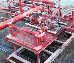
Figure 5. Choke manifold
The blowout preventer (BOP), accumulator and choke manifold are installed by the rig crew after the surface casing is set and cemented. The accumulator and choke manifold have been set into place during rigging up and now need to be hooked up and tested. The choke line valve is used to redirect the mud from the well bore to the choke manifold during a kick. The kill line valve is used to direct drilling fluid to the BOP during a kick.
Potential Hazards:
- Being crushed by falling equipment if hoisting slings fail.
- Being struck by, pinched by or caught between equipment during installation.
Possible Solutions:
- Ensure workers stand clear of equipment being hoisted and tag lines are used where appropriate.
- Coordinate hoisting tasks with rig crew.
- Inspect the hoisting slings for wear before any hoisting operation.
- Ensure all personnel wear proper PPE.
Additional Resources:
- Standards. American Petroleum Institute (API).
- RP 53, Blowout Prevention Equipment Systems for Drilling Operations. Second Edition, (2006, May). Provides information that can serve as a guide for installation and testing of blowout prevention equipment systems on land and marine drilling rigs (barge, platform, bottom-supported, and floating). This is the recommended specification for the installation, use, and maintenance of this equipment.

Figure 6. Choke manifold
The BOPs, accumulators, and choke manifold should be tested and properly maintained.
Potential Hazards:
- Being hit by hoses or sprayed by hydraulic fluid if there is a seal or hydraulic line failure during pressure testing.
Possible Solutions:
- Ensure workers stand clear of pressurized lines during testing procedures.
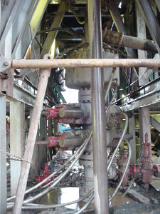
Figure 7. Blowout preventer
Properly maintain the surface control system.
Potential Hazards:
- Protruding pipes and objects.
- Being struck by dropped objects.
- Slips, trips, and falls.
- Atmospheric hazards
Possible Solutions:
- Wear appropriate personal protective equipment (such as hard hats, work gloves, safety shoes, and eye protection).
- Implement injury awareness training (such as dropped objects, working from heights)
- Use appropriate fall protection.
- Ensure workers are aware of the slipping and falling hazards.
- Monitor for potential hazards (H2S, methane, O2 deficiency).
#10. Blowout Preventer
One or more valves installed at the wellhead to prevent the escape of pressure either in the annular space between the casing and the drill pipe or in open hole (for example, hole with no drill pipe) during drilling or completion operations. See annular blowout preventer and ram blowout preventer.†s

#48. Ram Blowout Preventer
A blowout preventer that uses rams to seal off pressure on a hole that is with or without pipe. It is also called a ram preventer. Ram-type preventers have interchangeable ram blocks to accommodate different O.D. drill pipe, casing, or tubing.†

Annular Blowout Preventer
A large valve, usually installed above the ram preventers, that forms a seal in the annular space between the pipe and well bore. If no pipe is present, it forms a seal on the well bore itself. See blowout preventer.†

#25. Accumulator
The storage device for nitrogen pressurized hydraulic fluid, which is used in operating the blowout preventers.†


#22. Choke Manifold
The arrangement of piping and special valves, called chokes, through which drilling mud is circulated when the blowout preventers are closed to control the pressures encountered during a kick.†

#56. Surface Casing
Usually the first casing to be run in a well. This is done after spudding-in so a blowout preventer can be installed before drilling is started.†
