Non-Destructive Evaluation (NDE) and Testing Facilities
X-ray inspection systems
|
|
PDF version [140KB] |
The Non-destructive Evaluation group operates two, industrial, x-ray inspection systems that are used primarily to characterize internal features of one-of-a-kind engineering samples and/or high-value components.
- Both systems utilize commercial, solid-state, imaging detectors to produce electronic/digital images of the components under test.
- Multi-axis, motion-controlled stages are coordinated with image acquisition to produce both conventional two-dimensional (2D) projection images and cross-sectional slices from three-dimensional (3D) volumetric data sets using Computed Tomography (CT).
- CT images are produced using software developed in-house for use with high-end desktop workstations or Linux-based Beowulf clusters.
- Digital images are acquired from either a 16-inch square area detector or a 36-inch long line detector.
- The systems are works in progress and can generate a CT slice from a 9-inch diameter object in less than 30 minutes.
- From image acquisition to final image display, all data is stored in computer memory. A raw image data size of up to 22 gigabytes/sample can be handled.
Description
X-rays are generated from either a 30 Watt, IRT HOMX-161 Micro-focus source or a 4200 Watt, Philips MG-450 industrial x-ray source which operate in a continuous, open beam mode. The sources, stages, samples, and detectors are enclosed in a shielded room with interlocked doors.
IRT HOMX-161 Micro-focus source
The Micro-Focus source can produce electron beam spot sizes between 5 and 200 microns on a water-cooled tungsten target. Smaller spot sizes produce better edge detail with the X-ray detector. The beam voltage may be varied between ~ 10 and 160 kVp. X-rays exit the source tube through an aluminum window in a 40 degree cone.
 Figure 1: HOMX-161 source (left) with PerkinElmer RID detector (behind lead shield). A carbon composite sample is located on the 3-axis controlled stage in front of the detector.
Click on photo to view a larger image.
Philips MG-450 industrial x-ray source
The Philips source can generate two beam spot sizes, 1500 and 4000 microns, on an oil-cooled tungsten target. The beam voltage may be varied between 20 and 420kVp. The beam current can be set between 0.1 and 10.0 mA. X-rays exit the source tube through a beryllium window in a 37-degree cone. The cone-beam X-ray allows image magnification as objects being examined are moved closer to the x-ray source. Practical magnification factors range between 1.1X and 5X.
 Figure
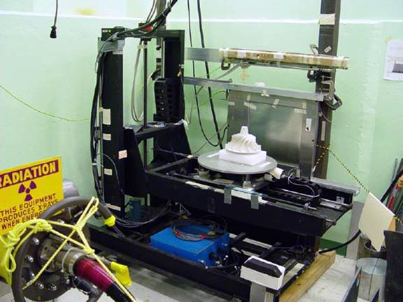
2: Philips MG-450 source with RID area detector and CMOS linear detector (above RID). A prototype
ceramic rotor is shown on the Multi-Axis controlled stage (in front of RID detector).
Figure
2: Philips MG-450 source with RID area detector and CMOS linear detector (above RID). A prototype
ceramic rotor is shown on the Multi-Axis controlled stage (in front of RID detector).
Click on photo to view a larger image.
Imaging
The X-ray radiation can be imaged by using:
- either a 16-inch square (419304 pixel) area detector at a resolution of 170 microns/pixel or
- by using a 36-inch long (11,116 pixel) line detector at a resolution of 75 microns/pixel.
The area detector is an array of 2048x2048 thin-film transistors (TFT). Each TFT has a sensitive area of 200 microns square.
The line detector is a linear array of 11,116 CMOS elements with each pixel having a sensitive area of 83 microns.
The detectors are interchangeable with either source.
Requisites for samples
Practical sample sizes can be:
- around 14 inches in diameter for the area detector and
- around 30 inches in diameter for the linear detector, which is limited by the image magnification.
Image Processing
- With custom software developed in-house for CT applications, cross-sectional slices of a 3D volume may be generated.
- Each CT slice is equal to the height of the sensitive pixel divided by the magnification factor (~1.1X to 5X).
- The reconstructed volume CT data may be manipulated with a software package such as IDL (ITT Visual Solutions) to visualize any slice within the 3D volume from an arbitrarily angle.
- Construction of 2D images that are larger than the physical limits of either detector is possible through the use of motion controlled positioning stages.
- The resulting overlapping images may be assembled electronically by using a number of commercial software packages such as Photoshop, Gimp, Scion, and IDL.
Related Documents
- Nondestructive Evaluation Technologies [ 756KB]
- X-ray inspection systems - Fact Sheet
[140KB]
Last Modified: Tue, July 17, 2012 5:19 PM