What Does This Section Cover? (Section 3.5.1)
The specific requirements for concrete pipe apply to the transportation of certain concrete pipe loaded crosswise on a platform trailer or vehicle.
What is exempt from these specific requirements?
Follow general cargo securement requirements (Section 2) when transporting the following pipe:
- Concrete pipe that is grouped together into a single rigid article and may not roll.
- Concrete pipe loaded in a sided vehicle or container.
- Concrete pipe eyes vertical and concrete pipe loaded lengthwise.
What is covered under these specific requirements?
- Any concrete pipe loaded crosswise on a platform trailer or vehicle that is not exempt.
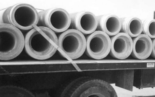
Securing Concrete Pipe
To make sure that concrete pipe does not roll or slide:
- Load pipe as compactly as possible.
- Immobilize symmetrically stacked pipes by securing them in groups.
- Use blocking systems and tiedowns to increase the effect of friction.
General tiedown requirements (Section 3.5.2)
- The aggregate working load limit of all tiedowns on any group of pipe must be more than half the total weight of all pipes in the group.
- Run a properly tensioned tiedown through a pipe in an upper tier or over lengthwise tiedowns. It will secure all the pipe beneath it on which the tiedown causes pressure.
Blocking requirements (Section 3.5.3)
- Blocking must prevent the pipe from rolling or rotating.
- Blocking may be one or more pieces placed at equal distances from the center of a pipe
- There are two blocking options:
- Place one piece of blocking so that it extends at least half the distance from the center to each end of the pipe.
Blocking Option #1
- Place two pieces of blocking at the outside quarter points.
Blocking Option #2
- Blocking must be:
- Placed against the pipe
- Secured to prevent it from moving out from under the pipe.
- Timber blocking must have a minimum nominal dimension of 10 x 15 cm (4 x 6 in).
Arranging the Load (Section 3.5.4)
Requirements for arranging pipe with different diameter (Section 3.5.4.1)
- Load pipe of more than one diameter in groups that consist of pipe of only one size.
- Secure each group of pipe separately.
Arranging pipe with different diameter
Requirements for arranging a bottom tier (Section 3.5.4.2)
There are two ways to arrange the bottom tier:
- Cover the full length of the vehicle.

Arranging a bottom tier - Option #1
- Arrange as a partial tier in one or two groups.
Arranging a bottom tier - Option #2
Requirements for arranging an upper tier (Section 3.5.4.3)
- Place pipe only in the wells formed by pipes in the tier below.
- Do not start an additional tier unless all wells in the tier beneath are filled.
Requirements for arranging the top tier (Section 3.5.4.4)
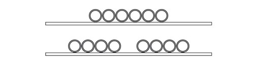
- Arrange the top tier as a complete tier, a partial tier in one group, or a partial tier in two groups.

Complete tier

Partial tier in one group

Partial tier in two groups
Requirements for arranging bell pipe (Section 3.5.4.5)
On spacers
- Load bell pipe on at least two longitudinal spacers tall enough to ensure that the bell is clear of the deck.
One tier
- Load bell pipe on one tier so that the bells alternate on opposite sides of the vehicle.
- If possible, the ends of consecutive pipe must be staggered within the allowable width.
- If the ends cannot be staggered, they must be aligned.
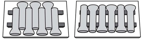
Staggered endsAligned ends
More than one tier with complete tiers
- Bells of the bottom tier must all be on the same side of the vehicle
- Bells of the upper tiers must be are on the opposite side of the vehicle from the bells of the tier below.

Alternate bell ends from tier to tier
More than one tier with partial upper tier
- Pipe in the bottom tier that do not support a pipe above must have their bells alternating on opposite sides of the vehicle.
![[Diagram of bell pipes on the bottom row are layed in one direction and the pipes in the top row are alligned in the opposite direction. This top row only covers one end of the bottom row.]](https://webarchive.library.unt.edu/web/20161102021717im_/https://www.fmcsa.dot.gov/sites/fmcsa.dot.gov/files/pictures/cargosecurement-16-04-rob-img-129_500px.jpg)
Alternate bell ends when pipe on bottom does not support pipe above
Special Circumstances: Securing Pipe with an Inside Diameter Up to 1.143 mm (45 in) (Section 3.5.5)
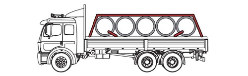
Concrete pipe with an inside diameter up to 1.143 m (45 in) can form a complete single tier on a typical flatbed vehicle. Larger pipe often can only be carried as a partial tier.
Note: This pipe diameter of 1.143 m (45 in) is simply a convenient breaking point between "medium" and "large" diameter pipe.
Note: At least one tiedown through the front pipe of the bottom tier must run rearward at an angle not more than 45 with the horizontal when viewed from the side of the vehicle, when ever practical.
At least one tiedown through the rear pipe of the bottom tier must run forward at an angle not more than 45 with the horizontal when viewed from the side of the vehicle, when ever practical.
Requirements for stabilizing the bottom tier (Section 3.5.5.1)
- Arrange the load properly (see 3.5.4)
- Immobilize the front and rear pipe with on of the following elements.
- Blocking
- Wedges
- Vehicle end structure
- Stakes
- Locked pipe unloader
- Other equivalent means
Appropriate stabilization of bottom tier
Tiedown requirements (Section 3.5.5.2)
- Pipe many be secured individually or as a group.
- Tiedowns through the pipe must be chains.
- Front-to-back tiedowns may be chain or wire rope.
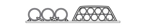
Individually
- Run a tiedown though the pipe.
As a group
- Place lengthwise tiedowns over the group of pipes:
- Either one 13 mm (1/2 in) chain or wire rope
- Or two 10 mm (3/8 in) diameter chain or wire rope
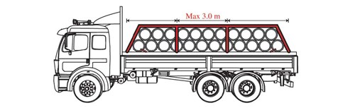
- Place one crosswise tiedown for every 3.0 m (10 ft) of load length.
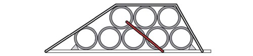
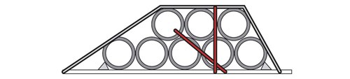
- Either attach the side-to-side tiedown through a pipe
- Or pass the tiedown over both front-to-back tiedowns between two pipes on the top tier.
Appropriate use of tiedowns for a group of pipes
Requirements for stabilizing the top tier (Section 3.5.5.2)
If the first pipe of a group in the top tier is not at the front of the tier beneath:
- Attach an additional tiedown that runs rearward at an angle not more than 45 to the horizontal when viewed from the side of the vehicle, whenever practicle.
- Pass tiedown either through the front pipe of the upper tier or outside the front pipe and over both longitudinal tiedowns.
Correct securement of front pipe in partial second tier
Correct securement of front pipe in partial
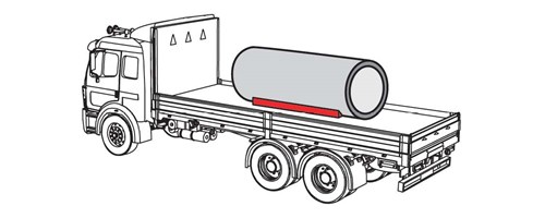
Special Circumstances: Securing Large Pipe with an Inside Diameter over 1143 mm (45 in) (Section 3.5.6)
Requirements for stabilizing the pipe
Arrange the load properly (see 3.5.4)
Immobilize the front and rear pipe with on of the following methods:
- Blocking
- Wedges
- Vehicle end structure
- Stakes
- Locked pipe unloader
- Other equivalent means
For all other pipe, use additional blocks and/or wedges that are nailed in place.
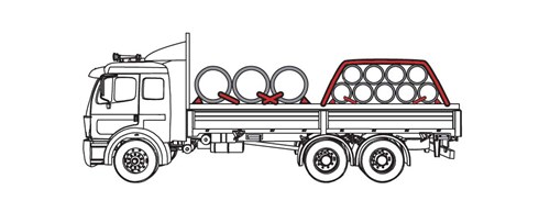
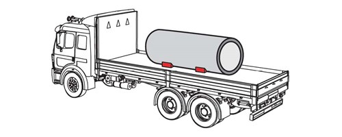
Requirements for securing the pipe
Secure each pipe with tiedowns through the pipe.
Run at least one tiedown through each pipe in the front half of the load. This includes the middle one if there are an odd number. The tiedown must run rearward at an angle not more than 45 with the horizontal when viewed from the side of the vehicle, whenever practicable.
Run at least one tiedown through each pipe in the rear half of the load. The tiedown must run forward at an angle not more than 45 with the horizontal when viewed from the side of the vehicle, whenever practicable. This holds each pipe firmly in contact with adjacent pipe.
Run at least two tiedowns through the front and rear pipe if they are not also in contact with vehicle end structure, stakes, a locked pipe unloader, or other equivalent means.
[Diagram of three concrete pipes next to one another. There are blocker bars at each end of the set and bars connecting each pipe.]
Correct securement of large pipe
Run at least two tiedowns through the front and rear pipe if they are not also in contact with one of the following:
- Either the vehicle end structure
- Or the stakes
- Or a locked pipe unloader
- Or other equivalent means.
[Note:] If only one pipe is transported, or if several pipes are transported without contact between other pipes, the requirements of this section apply to each pipe as a single front and rear article. Tiedowns must be used through that pipe.