|
Concept
of Operations and
Voluntary Operational Requirements
for
Vehicular Stability Systems (VSS)
On-board Commercial Motor Vehicles  | July
2005 |
Foreword The Federal Motor Carrier Safety Administration’s (FMCSA’s) safety goal
is to reduce the number and severity of large truck fatalities and crashes.
During the last several years, FMCSA has collaborated with the trucking industry
to test and evaluate several on-board safety systems for commercial motor vehicles
to increase the safety and security of all roadway users. FMCSA is now promoting
voluntary adoption of these systems within trucking fleets by initiating steps
to work closely with the trucking industry to define vendor-independent, voluntary
requirements. The purpose of this document is to relay a better understanding of the functions
of on-board safety systems for vehicle stability and to provide insight into
the safety and efficiency benefits of using the systems. This document describes
the concept of operations and voluntary requirements for Vehicle Stability Systems
(VSS) for large trucks greater than 10,000 pounds gross vehicle weight rating
(GVWR). Concepts of operations provide information about how each user interacts
with these safety systems and their operational conditions. Voluntary requirements
describe features and functions used to define the safety systems and their
operational functionality. The information has been developed in collaboration
with trucking industry stakeholders, including representatives from manufacturers,
insurance companies, commercial vehicle carriers, drivers and academia. The results from this project can be used by motor carriers as system guidelines
for voluntary adoption of on-board safety systems within their trucking fleets. This is a final report developed under FMCSA’s deployment of on-board
safety system program. It does not supersede an earlier report on the subject.
Notice
This document is disseminated under the sponsorship of the Department of Transportation
in the interest of information exchange. The United States Government assumes
no liability for its contents or use thereof. This report does not constitute a standard, specification, or regulation. The United States Government does not endorse products or manufacturers. Trade
or manufacturers' names appear herein only because they are considered essential
to the object of this document. Acknowledgements FMCSA wishes to acknowledge the efforts of those in the government, academia,
research institutions and industry who contributed their knowledge and expertise
to this effort. Those individuals include Carl Kirk and Robert Braswell of the
Technology and Maintenance Council; Marty Fletcher of US Xpress; Jim Kennedy
of McKenzie Tanklines; Ron Knipling, PhD of the Virginia Tech Transportation
Institute; Scott Claffey of Great West Insurance Company; Dave Melton of Liberty
Mutual Research Institute for Safety; Anne McCartt, PhD of the Insurance Institute
for Highway Safety; Rick Craig of the Owner Operators Independent Drivers Association;
Bill Gouse of the American Trucking Associations; Tom Moses of the Spill Center;
Bob Interbitzen of the National Private Truck Council; Mike Formica and Dean
Pomerleau, PhD of Assistware; Bill Patrolia of Iteris; Meny Benady of Mobileye;
Kevin Romanchok, Jim Szudy, and Richard Beyer of Bendix; Alan Korn, Richard
Romer, and Mike Lambie of Meritor WABCO; Greg Shipman of Delphi; Tom Mattox
of Eaton VORAD; Skip Yeakel of Volvo; Charlie Groeller of Mack Trucks; Paul
Menig of Freightliner; and Dan Murray of the American Transportation Research
Institute.
Technical Report
Documentation Page 1. Report
#
FMCSA-MCRR-05-006
| 2. Government
Accession # | 3. Recipient's
Catalog # | 4.
Title and Subtitle
Concept of Operations and Voluntary Operational Requirements for Vehicular
Stability Systems (VSS) On-board Commercial Motor Vehicles | 5. Report
Date
July 2005 | 6. Performing
Organization Code
| 7.
Author (s)
Amy Houser (FMCSA), John Pierowicz (Calspan Corp.), Dan Fuglewicz (Calspan
Corp.) | 8. Performing
Organization Report # | 9.
Performing Organization Name and Address
Calspan Corporation
4455 Genesee Street
Buffalo, NY 14225 | 10.
Work Unit # (TRAIS) | 11. Contract
or Grant #
DTMC75-03-F-00087 | 12.
Sponsoring Agency Name and Address
Federal Motor Carrier Safety Administration
Office of Research and Analysis
400 Virginia Ave. SW
Washington, DC 20024 | 13.
Type of Report and Period Covered
Technical Report -
October 2003-July 2005 | 14. Sponsoring
Agency Code
FMCSA | 15.
Supplementary Notes
This program was administered through the Federal Motor Carrier
Safety Administration (FMCSA). The
FMCSA Program Manager is Mrs. Amy Houser. | 16.
Abstract The Federal Motor Carrier Safety Administration’s
(FMCSA’s) safety goal is to reduce the number
and severity of large truck fatalities and crashes. During the last
several years,
FMCSA has collaborated with the trucking industry to test
and evaluate several on-board safety systems for commercial motor vehicles
to increase the safety and security of all roadway users.
FMCSA is now promoting voluntary adoption of these systems
within trucking fleets by initiating steps to work closely with the
trucking industry to define vendor-independent, voluntary requirements.
The purpose of this document is to relay a better understanding
of the functions of on-board safety systems and to provide insight into
the safety and efficiency benefits of using the systems. The information
has been developed in collaboration with expert panels consisting of
trucking industry stakeholders, including representatives from manufacturers,
insurance companies, commercial motor vehicle carriers, drivers, and
academia. This document describes the concept of operations and
voluntary requirements for Vehicle Stability Systems (VSS) for large
trucks greater than 10,000 pounds gross vehicle weight rating (GVWR).
Concepts of operations provide information about how each user interacts
with these safety systems and their operational conditions. Voluntary
requirements describe features and functions used to define the safety
systems and their operational functionality. | 17.
Keywords
Active Safety Systems, Commercial Motor Vehicles, Heavy Trucks, Tractor-Trailers,
Vehicle Stability Systems | 18.
Distribution Statement
| 19. Security
Classif. (of this report)
Unclassified | 20. Security
Classif. (of this page)
Unclassified | 21. #
of Pages
23 | 22. Price |
| | Form DOT F1700.7 (8-72) | Reproduction of complete page authorized. |
SI*
(MODERN METRIC) CONVERSION FACTORS
APPROXIMATE CONVERSIONS TO SI UNITS | Symbol | When
You Know | Multiply
By | To
Find | Symbol |
|---|
| LENGTH |
|---|
| In |
inches |
25.4 |
millimeters | mm | | Ft | feet |
0.305 |
meters | m | | Yd |
yards |
0.914 |
meters | m | | Mi |
miles |
1.61 |
kilometers | km | | AREA |
|---|
| in2 |
square inches |
645.2 |
square millimeters |
mm2 | | ft2 |
square feet | 0.093
|
square meters |
m2 | | yd2 |
square yards |
0.836 |
square meters |
m2 | | Ac |
acres |
0.405 |
hectares |
ha | | mi2 |
square miles |
2.59 |
square kilometers |
km2 | | VOLUME |
|---|
| fl
oz |
fluid ounces |
29.57 |
milliliters |
ml | | Gal |
gallons |
3.785 |
liters |
l | | ft33 |
cubic feet | 0.028 |
cubic meters |
m3 | | yd3 |
cubic yards |
0.765 |
cubic meters |
m3 | | MASS |
|---|
| Oz |
ounces |
28.35 |
grams |
g | | Lb |
pounds |
0.454 |
kilograms |
kg | | T |
short tons (2000 lbs) |
0.907 |
megagrams |
Mg | | TEMPERATURE
(exact) |
|---|
| F
| Fahrenheit |
5(F-32)/9 |
Celsius |
C | | |
temperature |
or (F-32)/1.8 |
temperature | | | ILLUMINATION |
|---|
| Fc |
foot-candles |
10.76 |
lux |
lx | | Fl
| foot-Lamberts |
3.426 |
candela/m2 |
cd/m2 | | FORCE
and PRESSURE or STRESS |
|---|
| Lbf |
pound-force |
4.45 |
newtons |
N | | Psi
|
pound-force per square inch |
6.89 |
kilopascals |
kPa |
|
APPROXIMATE CONVERSIONS FROM SI UNITS
| Symbol | When
You Know | Multiply
By | To
Find | Symbol |
|---|
| LENGTH |
|---|
| mm | millimeters | 0.039 | inches | in | | m | meters | 3.28 | feet
| ft | | m | meters | 1.09 | Yards | yd | | km | kilometers | 0.621 | miles | mi | | AREA |
|---|
| mm2 |
square millimeters |
0.0016 |
square inches | in2 | | m2 |
square meters | 10.764 | square
feet |
ft2 | | m2 |
square meters |
1.195 |
square yards |
yd2 | | ha |
hectares | 2.47 | acres | ac | | km2 |
square kilometers | 0.386 |
square miles | mi2 | | VOLUME |
|---|
| ml | milliliters |
0.034 |
fluid ounces |
fl oz | | l | liters |
0.264 |
gallons |
gal | | m3 |
cubic meters |
35.71 | cubic
feet |
ft3 | | m3 | cubic
meters |
1.307 |
cubic yards |
yd3 | | MASS |
|---|
| g |
grams |
0.035 | ounces | oz | | kg |
kilograms | 2.202 |
pounds | lb | | Mg | megagrams | 1.103 | short
tons (2000 lbs) |
T | | TEMPERATURE
(exact) |
|---|
| C
| Celsius | 1.8
C + 32 |
Fahrenheit |
F | | |
temperature | |
temperature | | | ILLUMINATION |
|---|
| lx | lux |
0.0929 |
foot-candles |
fc | | cd/m2
| candela/m2 | 0.2919 |
foot-Lamberts |
fl | | FORCE
and PRESSURE or STRESS |
|---|
| N | newtons | 0.225 | pound-force | lbf | | kPa
|
kilopascals | 0.145 | pound-force
per square inch | psi
|
|
* SI is the symbol for
the International System of Units. Appropriate rounding should be made to
comply with Section 4 of ASTM E380. 1. INTRODUCTIONThe Federal Motor Carrier Safety Administration’s (FMCSA’s) safety
goal is to reduce the number and severity of large truck fatalities and crashes.
During the last several years, FMCSA has collaborated with the trucking industry
to test and evaluate several on-board safety systems for commercial motor vehicles
to increase the safety and security of all roadway users. FMCSA is now promoting
voluntary adoption of these systems within trucking fleets by initiating steps
to work closely with the trucking industry to define vendor-independent, voluntary
requirements for these systems. The purpose of this document is to relay a better understanding of the functions
of on-board safety systems and to provide insight into the safety and efficiency
benefits of using the systems. The information has been developed in collaboration
with expert panels consisting of trucking industry stakeholders, including representatives
from manufacturers, insurance companies, commercial motor vehicle carriers,
drivers, and academia. This document describes the concept of operations and voluntary requirements
for Vehicular Stability Systems (VSS) for large trucks (greater
than 10,000 pounds gross vehicle weight rating). VSS include:
Roll Stability Advisor (RSA), Roll Stability Control (RSC),
and Electronic Stability Control (ESC) systems. Concepts
of operations provide information about how each user interacts with these safety
systems and their operational conditions. Voluntary requirements describe features
and functions used to define the safety systems and their operational functionality.
This document discusses VSS provided by manufacturers, such as: - Bendix Commercial Vehicle Systems
- Freightliner
- Meritor WABCO Vehicle Control Systems
Appendix A lists the commercial off-the-shelf (COTS) systems
that currently exist or will be released to the market. United States Department
of Transportation (USDOT) websites that contain further information
on governmental research, testing and evaluation of
VSS include: www.its.dot.gov/ivi/ivi.htm
www.fmcsa.dot.gov/safetyprogs/research/researchpubs.htm
2. CONCEPT OF OPERATIONS Roll Stability Roll stability systems automatically apply brakes to counteract the tendency
of a vehicle to tip over while cornering at high speed. The tires provide a
lateral (sideways) force at the road to turn the vehicle, as shown in Figure
1, where the truck is turning to the left. The inertia of the vehicle, which
tends to continue in a straight line, creates an opposing lateral force effectively
acting at the vehicle’s center of gravity, as indicated by Flat in Figure
1. The vehicle will lean away from the curve; and, if the opposing lateral forces
are great enough, the vehicle will roll over. Other factors that influence the
sensitivity of a vehicle to rollover include: the vehicle’s load center
of gravity height, load offset, road adhesion, road cross slope, suspension
stiffness, frame stiffness, and track width (distance between the tires).
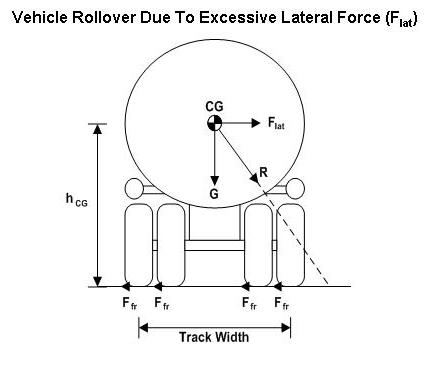
Figure 1
Key RSC System Parameters(For illustration only – not to scale.) Yaw Stability
ESC systems use automatic braking of individual wheels to prevent the vehicle’s
heading from changing too quickly (spinning out) or not quickly enough (plowing
out). With a combination-unit truck, a jackknife crash results from an oversteer
situation. The loss of traction can be caused by slippery roadway conditions
or excessive speed in a curve, which can cause a loss of directional control,
resulting in the tractor and trailer moving along separate paths. ESC systems
cannot increase the available traction, but they maximize the possibility of
keeping the vehicle under control and on the road during extreme maneuvers by
monitoring the driver’s natural reaction of steering in the intended direction
in oversteer and understeer situations. Figure 2 illustrates the understeer (plowing out) situation where a vehicle
enters a turn, the front of the vehicle slides or plows out, and the vehicle
proceeds to the edge of the curve leading to a roadway departure, if uncorrected.
Figure 3 illustrates the oversteer (spinning out) situation where a tractor-trailer
enters a turn, the drive axles slide or spin out, and the vehicle proceeds toward
the edge of the curve. If uncorrected, this situation can lead to a roadway
departure, jackknife for combination unit vehicles, or other conditions, such
as tripped rollovers. 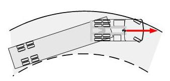
Figure 2
Illustration of Understeer Condition 
Figure 3
Illustration of Oversteer Condition
Description
- Vehicular Stability SystemsRoll Stability Advisor Operation Roll Stability Advisors (RSA) are passive systems that advise
the driver about recent conditions that presented a significant risk of rollover.
The RSA tested in the
USDOT field operational test (FOT), did not deliver
an immediate warning of an impending rollover. With the objective of modifying
driver performance in similar future driving situations,
RSA provided an advisory message within seconds after the event has
occurred. The electronic control unit (ECU) of the
RSA monitors lateral force information received from on-board sensors
to determine when an advisory is warranted. The advisory is an audible alert
and visual message to the driver. Increasing severity associated with the levels
of rollover risk is communicated through means, such as the wording of the message,
the length of display time, and the duration of an audible alert. For the system
tested in the USDOT FOT, the text messages are
displayed on two alternating screens: the first presents the qualitative advisory
on risk, and the second presents a quantitative advisory for reduced speed.
The speed reduction advisory is variable and calculated based on the observed
speed and lateral acceleration during the risky event. Roll Stability Control System Operation The roll stability control (RSC) system automatically intervenes if a high
rollover risk is detected while driving. If a rollover threat is occurring,
the system intervenes and tries to minimize the rollover risk by automatically
reducing the throttle and if necessary, applying the engine and foundation brakes
without action by the driver. RSC systems use drive axle, trailer axle, and
steer axle-braking. The RSC system is typically integrated with Antilock Braking
System (ABS) controllers, but some systems are integrated with electronically
controlled braking systems. Electronic Stability Control System Operation ESC systems, also
known as Electronic Stability Programs (ESP), are active
systems that automatically intervene when there is a high risk of roll over
or yaw instability. In currently available systems, the ECU
constantly compares the vehicle’s actual movement to performance models
using the wheel speed sensors, as well as lateral, yaw, and steering angle sensors.
If the vehicle shows a tendency to leave an appropriate travel path, or if critical
threshold values are approached, the system will intervene to assist the driver.
When a potential rollover risk is detected, the rollover function operates
as previously described. The
ESC system reduces the throttle and applies the proper brake pressure
to slow the vehicle below the rollover risk threshold. When a vehicle slide
(oversteer or understeer) is detected, the
ESC system removes the throttle and then selectively applies the appropriate
individual brakes to produce a counter-force to better align the vehicle with
an appropriate path of travel. In an oversteer situation, the system applies
the “outside” front brake; while in an understeer condition, the
"inside" rear brake is applied. These systems may be integrated with
electronically controlled braking systems or anti-lock braking systems. Crash PreventionVehicle Stability Systems can help prevent the following types of crashes.
This data is derived from the 2002 and 2003 General Estimates System (GES) Accident
database:[1] - Rollover – Large trucks were involved in 10,200
rollover crashes in 2002 according to the FMCSA publication “Large Truck
Crash Facts 2002”. These crashes resulted in 190 fatalities. Rollovers
can occur at speeds below 30 miles per hour, which can be too fast on an exit
ramp. With regard to excessive speed, drivers may be under the speed limit,
but operating too fast for conditions. Although drivers may think that they
know how fast the truck is traveling by the way it feels, their estimates
of speed can be off by 10 to 20 miles per hour. As a result, RSC and ESC systems
can reduce the speed of the vehicle to prevent many rollover incidents.
- Loss of Control Crashes – Many loss of control crashes
occur as the result of an aggressive control action by the driver. Steering
to avoid another vehicle and over-correction from a lane departure are typical
loss of control actions. In 2003, large trucks accounted for approximately
9,600 loss of control crashes resulting in 230 fatalities.
ESC systems use automatic braking of individual wheels to prevent
the vehicle’s heading from changing too quickly (spinning out) or not
quickly enough (plowing out).
ESC and
RSC systems will not prevent all crashes, such as tripped rollovers
and those caused by sudden turns at high speed or travel on cross-sloped shoulders.
Operations
and UsersThis section describes how drivers, fleet managers, and fleet maintenance personnel
interact with VSS
and potential benefits that each stakeholder may realize with
these systems. The commercial vehicle population is comprised of a wide variety of vehicle
types and uses. At a high level, two types of vehicles are predominant, combination
vehicles (tractors-trailers) and straight trucks. These two types of vehicles
have very different operating characteristics. In general, straight trucks tend
to be used in a more local setting and used to provide deliveries of goods and
services to customers generally within a 50 to 100 mile radius of their base
of operations. Combination vehicles are more often utilized in regional and
long distance applications and account for about 30% of total commercial vehicles,
but 65% of the commercial vehicle miles traveled. The trucking industry is actually a broad collection of many industries, each
with operating characteristics as diverse as the industries they service. Segmentation
of the trucking industry is often based on the size of fleets, the geographic
range of its operations, and the commodities hauled. Usually one characteristic
is not adequate to describe a particular segment, but rather combinations of
characteristics are required to best describe operations. For example, there
may be a trucking firm with a large fleet providing package delivery type service
to a relatively small geographic area, while there may be a single truck company
that provides general freight services to all states in the continental United
States. The movement of goods by truck is conducted on all types of roads, at all hours
of the day, and in all types of driving conditions. Since loss of vehicle stability
can occur along any route, many fleet types may benefit from using
VSS, yet they may be most promising for tractor-trailer combinations,
trucks with high mileage accumulated over their operational life, or trucks
that operate under conditions that may present driving challenges, such as roadways
of geometry or configuration that can be difficult to negotiate. The value of the system to a fleet or an owner-operator depends on the risk
of these crashes in the particular business and the cost of the crashes. During
the USDOT FOT, the RSA and RSC systems were found to be particularly beneficial
for fleets with tractors pulling tank trailers. Additional secondary benefits
may be derived from the prevention of the previously mentioned severe crashes
involving cargo loss by lowering costs of clean up and reducing traffic congestion.
Drivers Drivers are the primary VSS
users. They interact with the system in a number
of basic driving and operating situations: Normal system startup operation – When the driver
starts the vehicle, the VSS
performs a power-up self-test, and the driver
scans the warning indicator to determine any system malfunctions. If necessary,
the driver may alert fleet maintenance for corrective action. Vehicle stability
events – When a driver transverses a curve at an excessive
speed in a rollover risk situation,
RSC and ESC
systems automatically initiate braking to slow the vehicle without driver
intervention. During a loss of control situation due to sliding, the
ESC system initiates braking. The RSA issues an advisory message to the driver following the
detection of a rollover risk. The
RSC and ESC
systems may provide audible and/or visual warnings to the driver about the
rollover risk and activation of automatic braking. System fault conditions – If a VSS
system fault occurs,
a system status indicator will alert the driver; however, the vehicle will
operate normally. The driver may be notified of a VSS
system fault via an
audible alert or visual message. Various road types and conditions – A driver may encounter
several types of roads and conditions. Normally, VSS
will be in a monitoring
mode during driving situations. Most untripped rollovers caused by lateral
acceleration occur on curved roads and exit ramps. On flat roadways, rollovers
occur on dry pavement when the roadway friction prevents the vehicle from
sliding sideways. Jackknifing, plowing out, and spinning out tend to occur
on roadways with reduced traction. The driver should be aware that in limited-traction
conditions, RSC systems will not prevent limited-traction, sliding incidents
while ESC systems address both sliding and rollover situations.
Fleet ManagementFleet managers are responsible for all administrative, financial, and operational
aspects of the fleet. Safety officers focus on the fleet’s operational
safety issues and examine the operational safety aspects of the fleet’s
vehicles in accordance with
USDOT safety regulations. They also work with drivers to provide safety
and operational training, verify that drivers are completing their hours-of-service
requirements, and examine how well drivers operate their vehicles (e.g., logging
accidents and traffic infractions). These personnel examine various types of available safety equipment, justify
the purchase of all equipment, determine the effectiveness of this equipment,
and calculate the return on investment (ROI) for their fleet. They work with
the maintenance department and drivers to explain VSS
benefits. Using operational
data from VSS
via the in-vehicle network, fleet managers may analyze the data
to review systemic problems with their fleet operations (e.g., disproportionate
number of rollover warnings with certain drivers) and to train drivers. Safety
managers have a number of theories about the primary causes of tanker rollovers.
They point to four basic factors: excessive speed, driver inattention, driver
fatigue, and inadequate training and experience.[2]
Research has indicated that the monitoring of driver behavior can have a positive
effect on driver and fleet safety.[3], [4] Maintenance
Management and InstallationMaintenance managers and service technicians are responsible for the proper
functioning of all equipment installed on the fleet’s vehicles and for
installing and maintaining VSS
on the fleet. They support fleet management by
collecting operational data on the reliability of VSS
and how well VSS
suppliers
work with the fleet to resolve any problems. Since VSS
are typically an extension of ABS, the maintenance requirements for
a vehicle equipped with VSS
should not be more complicated than requirements
for standard ABS. 3. VOLUNTARY REQUIREMENTSThe voluntary requirements included in the following sections define fundamental
VSS
features and the ability of the VSS
to withstand the electrical and environmental
extremes commonly found on commercial vehicles. The types of voluntary requirements for VSS
include: - Functional Requirements
- Data Requirements
- Hardware and Software Requirements
- Driver Vehicle Interface (DVI) Requirements
- Maintenance and Support Requirements
VSS manufacturers may
include additional functions and features that may be useful beyond minimum
VSS functionality; the
operational features that fall into this category are labeled with the term
“OPTIONAL”. However, in all cases
VSS must comply with all existing
FMCSA Safety Regulations. The requirement numbering system designates
optional features with a “T” and system defining requirements with
an “R”. 3.1 Functional
RequirementsFunctional requirements described here refer to basic system functionality
and operation of all types of VSS. R1-1 | VSS
should perform a self-test to test all major system components and be fully
operational within 30 seconds of starting the vehicle, and relay the results
of the self-test to the driver.
| R1-2 | VSS
should
be able to provide vehicle dynamics monitoring, control actions, and/or
warnings in all lighting conditions (e.g., bright sunlight, moonless night,
dusk/dawn, etc.).
| R1-3 | VSS
should
be able to provide vehicle dynamics monitoring, control actions, and/or
warnings in all weather conditions (e.g., dry, rain, snow, ice, fog, etc.).
| R1-4 | RSC and ESC
systems should be capable of control actions when the vehicle is moving
at least 16 kph (10 mph). Vehicle instability can occur at low speeds on
certain graded roadways (e.g., down-grade tight-turn driveways).
| R1-5 | VSS should dynamically calculate rollover thresholds
based on changing vehicle parameters. For example, currently available
VSS estimate the vehicle’s center-of-gravity (CG)
height based on the vehicle’s mass, including its cargo.
| R1-6 | RSC and ESC
systems should use foundation brakes to reduce the speed of the vehicle
to minimize the risk of rollover. ESC systems should use foundation brakes
to reduce the speed of the vehicle to minimize the risk of oversteer or
understeer situations. RSC and ESC systems may also use other control actions,
such as engine dethrottling, retarder activation, and transmission downshifting,
as appropriate.
| R1-7 | RSC and ESC
systems should blend the braking demands of the system and the driver so
that the higher braking demand takes precedence. By directly measuring driver
brake demand, RSC and ESC systems should accurately transition between driver-intended
and system-intended braking pressure.
| R1-8 | If integrated
with RSC and ESC systems, ABS functionality should be maintained to manage
wheel slip and wheel lock conditions.
| T1-1 | OPTIONAL –
ESC, RSC, and
RSA systems may be integrated into one system, and they may be integrated
into ABS and traction-control systems.
| T1-2 | OPTIONAL – RSC and ESC systems may produce a net
vehicle speed that is lower than the posted speed limit for a particular
set of operating conditions when an impending rollover is detected and control
actions are taken.
|
3.2 Data RequirementsData requirements define the format of data generated by or can be obtained
directly in real-time from VSS
systems. Two Society of Automotive Engineers
(SAE) standards specify in-vehicle data communication in heavy trucks: - SAE J1587, “Electronic Data Interchange between Microcomputer Systems
in Heavy-Duty Vehicle Applications” (message definition for the J1708
data bus), or
- SAE J1939-71, “Recommended Practice for Control and Communications
Network for On-Highway Equipment – Vehicle Application Layer”
Although neither of these standards defines VSS
messages, it would be beneficial
for system users if VSS
suppliers adopt a common set of standard VSS
messages
for users to obtain diagnostic data via the in-vehicle data network. T2-1 | OPTIONAL – VSS
may provide operational
data to the SAE J-1708 or J-1939 data network in a format compatible to
the SAE standard.
| T2-2 | OPTIONAL – RSC and ESC systems may record data
on-board, which can be used for other purposes, such as evaluation of driver
performance and warning system performance.
|
3.3 Hardware and
Software RequirementsHardware and software requirements deal directly with the detailed functionality
of the hardware, environmental and electrical concerns, mounting/installation
issues, and software design. Figures 4 through 6 illustrate the major functional
components and interfaces of RSA,
RSC, and ESC
systems as described in the following sections, respectively. Figure 4 shows
the inter-relationship of the RSA
system components. The ESC
obtains the lateral force or acceleration data. Through the vehicle network
(J1708 or J1939), the ECU
transmits messages to the vehicle message center, where they can be seen by
the driver. Messages might be status indicators or alerts. Figure 5 shows the
inter-relationship of the RSC
system components. The RSC
has all the same components of the RSA
system. In addition, the ECU
can send a signal to ABS
control, commanding it to apply vehicle foundation brakes. Figure 6 shows the
inter-relationship of the ESC
system components. The ESC
has all the same components of the RSC
system. The ESC requires
two additional inputs—the vehicle’s yaw rate and the steering wheel
angle. 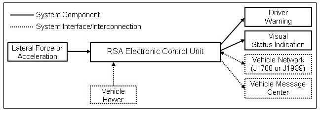
Figure 4
RSA Major Functional Components
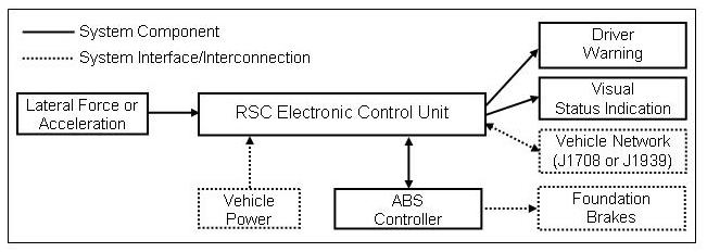
Figure 5
RSC System Major Functional Components

Figure 6
ESC System Major Functional Components
Typical System Hardware
This section describes the functionality of the primary physical components
of the VSS. They refer to the functional blocks as shown
in Figure 4 through 6. R3-1 | Lateral
Force or Acceleration – VSS
should provide a sensor to measure
the vehicle’s lateral acceleration. The sensor may reside within a
VSS
or be a discrete sensor.
| R3-2 | Yaw rate sensor –
ESC systems should provide a sensor to measure the vehicle’s
yaw rate. This sensor may reside within an
ESC system or be a discrete sensor.
| R3-3 | Steering angle sensor – ESC systems should provide
a sensor to measure the vehicle’s steering angle. This sensor typically
resides within the steering column and is used by an ESC system.
| R3-4 | Electronic Control Unit (ECU) –
The VSS ’s
ECU should be used to gather sensor data and calculating key parameters
used to determine the vehicle’s likelihood of rollover. The
ESC’s ECU
should also be used to gather sensor data and calculating key parameters
used to determine the vehicle’s likelihood of an oversteer or understeer
situation.
| R3-5 | Vehicle power – VSS
should rely on vehicle power
for operation.
| R3-6 | Visual status indication – VSS
should provide
a visual indication of the status of the system. System status includes
operational/non-operational and system fault conditions similar to the manner
in which ABS indicators are currently used. See Section 3.4 for additional
user interface requirements.
| R3-7 | Engine throttle control –
RSC systems should dethrottle the engine if a rollover is detected.
ESC systems should
also dethrottle the engine if an oversteer or understeer risk is detected.
| R3-8 | Engine brake –
RSC and ESC
systems should activate the engine brake (if vehicle is so equipped) if
a rollover is detected. ESC
systems should also activate the engine brake (if vehicle is so equipped)
if an oversteer or understeer risk is detected. | R3-9 | Foundation brakes – RSC and ESC systems should
activate the foundation brakes if a rollover is detected. ESC systems should
also activate the foundation brakes if an oversteer or understeer risk is
detected.
| R3-10 | Visual display – RSA systems should
use a visual display that presents operational messages to the driver to
indicate the risk of rollover.
| T3-1 | OPTIONAL – Driver warning –
RSC and
ESC systems may provide a warning to the driver when the systems
are actively controlling the vehicle. The warning can be audible, visual,
or tactile.
| T3-2 | OPTIONAL – Vehicle network –
VSS may use the in-vehicle data network (SAE
J1708, or J1939) for data communication to data recording or diagnostic
devices.
| T3-3 | OPTIONAL – Transmission Retardation
– RSC and ESC
systems may use the vehicle transmission to apply vehicle control actions. |
Environmental
RequirementsThe environmental conditions that exist in large trucks are severe. The SAE
has developed a comprehensive standard that describes various aspects of the
heavy truck environment in its J1455 standard. The standard also includes procedures
that are used to verify system compliance.
R3-11 | VSS
should meet the environmental requirements as stated in
the most recent version of the following SAE standard:
| | SAE Standard J1455, “Joint SAE/TMC
Recommended Environmental Practices for Electronic Equipment Design
(Heavy-Duty Trucks)”.
| | | The following environmental aspects are covered by the standard: | | | - Altitude
- Fungus
- Mechanical Shock
- Mechanical Vibration
- Relative Humidity
| - Temperature
- Salt Spray Atmosphere
- Immersion and Splash
- Steam Cleaning and Pressure Washing
- Dust, Sand, and Gravel Bombardment
|
Electrical
RequirementsIn a truck’s electrical power distribution system, the system voltage
may vary, the alternator may generate electrical noise, and various types of
transients may momentarily place over 100 volts direct current (VDC) on the
electrical distribution system’s wiring. In addition, there may be electrostatic
discharge into the system from a buildup of static electricity. Because VSS
connect to the truck’s electrical power distribution system, they should
function normally throughout all of these perturbations without damage. R3-12 | VSS should meet the electrical requirements
as stated in the most recent version of the following SAE
standards:
| | | SAE Standard J1455, “Joint SAE/Technology
Maintenance Council (TMC) Recommended Environmental Practices
for Electronic Equipment Design (Heavy-Duty Trucks)”.
SAE Standard J1113, “Electromagnetic Compatibility
Measurement Procedures and Limits for Vehicle Components (Except Aircraft)
(60 Hz to 18 GHz)”.
| | | The following environmental aspects are covered by the standards: - Steady State Electrical Characteristics
- Transient Electrical Characteristics
- Electromagnetic Susceptibility
- Electromagnetic Emission
| R3-13 | VSS
data should not be destroyed nor corrupted during a power surge.
|
Mounting and
Installation RequirementsMounting and installation requirements include all aspects related to the installation
of the VSS
hardware onto the truck, including the mounting of the individual
system components. There are no specific requirements pertaining to system size
or weight.
R3-13 | VSS
should use one or more fuses or other protective devices
to protect the vehicle’s power supply and power distribution wiring.
| R3-14 | All settings for the specific make and model of the vehicle should be
supplied to the installers, or VSS
should come pre-configured for use with
the vehicle.
| R3-15 | All VSS
cables, connectors, and components should be rated for automotive
duty as defined by the SAE and be appropriate for their operational environment
(e.g., VSS
components mounted on the exterior of the vehicle should be rated
for exterior duty).
| R3-16 | Major VSS
components, other than cabling or small mounting components,
should be marked with the manufacturer’s identification.
| R3-17 | VSS
in-cab components should remain securely mounted in the event of
a crash.
|
Software RequirementsSoftware requirements refer to the embedded software that runs in
VSS and controls all system functionality. The VSS’s
microcontroller or microprocessor continuously runs the system software when
the system is active.
T3-4 | OPTIONAL – The embedded software in
VSS may be field upgradeable via the in-vehicle network
connection (i.e., J1587 or J1939) or other common data interface (e.g.,
RS-232 or Universal Serial Bus (USB)).
| T3-5 | OPTIONAL – VSS
may include software for downloading
ASCII data files that can be easily read into a statistical, database, or
spreadsheet software package.
|
3.4 Driver Vehicle
Interface RequirementsThese requirements define specific ways in which VSS
interact/interface with
the driver, and include indicators, displays, and warning methods. As it applies
to VSS
driver interface issues, the National Highway Traffic Safety Administration
(NHTSA) Federal Motor Vehicle Safety Standard 101 (FMVSS 101) should be used
as a guide for VSS
indicators. R4-1 | VSS
should indicate to the driver that they are fully operational.
This indication may be performed by momentarily lighting a VSS
status indicator
lamp during power on system check, similar to the ABS lamp currently used
on large trucks.
| R4-2 | VSS should indicate
a system failure by continuously lighting a
VSS indicator lamp, similar to the
ABS system lamp currently used on large trucks.
| R4-3 | Warnings generated by VSS
should be clearly distinguishable from indicators
generated by other vehicle systems.
| R4-4 | VSS
should not have an on/off switch or a disable button.
| R4-5 | An indication or label should be supplied with the vehicle notifying the
driver that the vehicle has been equipped with a VSS.
| R4-6 | VSS
warnings, alerts, and messages should be readily understood by the
driver and not interfere with the driver’s primary duty of operating
the vehicle.[5]
| R4-7 | VSS
indicators should be clearly discernable in direct sunlight and should
not distract the driver in darkness.
| T4-1 | OPTIONAL – VSS
may provide a visual, audible, or
tactile warning to indicate a vehicle rollover is imminent or control actions
are taking place.
| T4-2 | OPTIONAL – VSS
may audibly indicate a system failure
or component malfunction.
| T4-3 | OPTIONAL – VSS
may allow the audible warning volume
to be adjusted, but not turned down completely.
| T4-4 | OPTIONAL – VSS
may provide diagnostic messages
such as “Sensor Failure” on an alphanumeric display to alert
the driver of specific problems or concerns.
|
3.5 Maintenance
and Support RequirementsMaintenance and support requirements include functionality/features that should
be provided to ensure VSS
systems will be operated correctly and properly maintained.
R5-1 | VSS
should require no more maintenance than that currently
required by available ABS systems. | R5-2 | VSS
should automatically maintain calibration. | R5-3 | A procedure to verify VSS
functionality and calibration should be provided
via an installation/maintenance manual or other document. | R5-4 | Users should be provided with a manual and training for VSS
. | R5-5 | The user’s manual should describe the minimum vehicle speed at
which the VSS
operates. It should also describe how the VSS
functions and
list the various rollover, oversteer, and understeer risk situations that
the VSS
can and cannot help mitigate. | R5-6 | Manufacturers should provide product support for users and fleets to
ask questions regarding capabilities and resolve problems with systems.
| T5-1 | OPTIONAL – The VSS
may provide blink codes, observed
at the system status indicator, that indicate various VSS
faults. | T5-2 | OPTIONAL – Video, audio, or computer-based training
material may be provided for fleet management and/or drivers. |
4. ACRONYMSAcronym | Definition |
|---|
| ABS | Antilock Braking System | | ASCII | American Standard Code Information Interchange | | CG | Center-of-Gravity | | COTS | Commercial Off-The-Shelf | | ECU | Electronic Control Unit | | ESC | Electronic Stability Control | | ESP | Electronic Stability Program | | FMCSA | Federal Motor Carrier Safety Administration | | FMVSS | Federal Motor Vehicle Safety Standard | | FOT | Field Operational Test | | GES | General Estimates System | | GVWR | Gross Vehicle Weight Rating | | kph | Kilometers per Hour | | mph | Miles per Hour | | NHTSA | National Highway Traffic Safety Administration | | ROI | Return on Investment | | RSA | Roll Stability Advisor(s) | | RSC | Roll Stability Controller(s) | | RSP | Roll Stability Program(s) | | SAE | Society of Automotive Engineers | | TMC | Technology and Maintenance Council | | USB | Universal Serial Bus | | USDOT | United States Department of Transportation | | VDC | Volts Direct Current | | VSS | Vehicular Stability System(s) |
5. REFERENCES
[1]The General Estimates System is directed
by the National Center for Statistics and Analysis, which is a component of
The Office of Research and Development in
NHTSA. Data for GES come from a nationally representative sample
of police reported motor vehicle crashes of all types, from minor to fatal.
The system began operation in 1988, and was created to identify traffic safety
problem areas, provide a basis for regulatory and consumer initiatives, and
form the basis for cost and benefit analyses of traffic safety initiatives.
The information is used to estimate how many motor vehicle crashes of different
kinds take place, and what happens when they occur.
[return to report] [2]Wilson, Charles E. Cargo Tank Rollovers
Need Industry Focus. Bulk Transporter. October 1, 2002.
[return to report] [3]Knipling, R.R. and Olsgard, P.J. Prospectus:
The Behavioral Power of On-Board Safety Monitoring Feedback. Proceedings of
the 10th Annual Meeting of the Intelligent Transportation Society of America
(ITS America), Boston, M.A., May 1-4, 2000.
[return to report] [4]Roetting, M.; Huang, Y.-H.; McDevitt,
J.R.; and Melton, D. When Technology Tells You How To Drive – Truck
Driver’s Attitudes Toward Feedback By Technology. Transportation Research
Part F, Elsevier Publishing, pp. 275-287, 2003.
[return to report] [5]FHWA, In-Vehicle
Display Icons and Other Information Elements: Volume II:
Final Report, Report No.FHWA-HRT-03-063,
September 2004.
[return to report]
FHWA, In-Vehicle Display Icons and Other Information Elements:
Volume II: Final Report, Report No.FHWA-HRT-03-063, September 2004. SAE Standard J1113, “Electromagnetic Compatibility
Measurement Procedures and Limits for Vehicle Components (Except Aircraft)
(60 Hz to 18 GHz)”, July 1995. SAE Standard J1455, “Joint SAE/TMC Recommended Environmental Practices
for Electronic Equipment Design (Heavy-Duty Trucks)”, August 1994. SAE Standard J1587, “Electronic Data Interchange between Microcomputer
Systems in Heavy-Duty Vehicle Applications”, February 2002. SAE Standard J1708, “Serial Data Communications between Microcomputer
Systems”, October 1993. SAE Standard J1939-71, “Recommended Practice for Control and Communications
Network for On-Highway Equipment – Vehicle Application Layer”,
September 2002. Wang, J.S.; Knipling, R.R.; and Blincoe, L.J. The Dimensions Of Motor Vehicle
Crash Risk. Journal of Transportation and Statistics. Volume 2, No.
1, pp. 19-43, ISSN 1094-8848,
May 1999. Knipling, R.R. and Olsgard, P.J. Prospectus: The Behavioral Power of On-Board
Safety Monitoring Feedback. Proceedings of the 10th Annual Meeting of the
Intelligent Transportation Society of America (ITS America),
Boston, M.A., May 1-4, 2000. Roetting, M.; Huang, Y.-H.; McDevitt, J.R.; and Melton, D. When Technology
Tells You How To Drive – Truck Driver’s Attitudes Toward Feedback
by Technology. Transportation Research Part F, Elsevier Publishing, pp. 275-287,
2003. Wierwille, W.W.; Lewin, M.G.; and Fairbanks, R.J. III.
Final Report: Research on Vehicle-Based Driver Status/Performance Monitoring;
Part I. Vehicle Analysis and Simulation Laboratory,
Virginia Polytechnic Institute and State University, Publication No.DOTHS 808 638, September 1996. Wierwille, W.W.; Lewin, M.G.; and Fairbanks, R.J. III.
Final Report: Research on Vehicle-Based Driver Status/Performance Monitoring;
Part II. Vehicle Analysis and Simulation Laboratory,
Virginia Polytechnic Institute and State University, Publication No.DOTHS 808 638, September 1996. Wierwille, W.W.; Lewin, M.G.; and Fairbanks, R.J. III.
Final Report: Research on Vehicle-Based Driver Status/Performance Monitoring;
Part III. Vehicle Analysis and Simulation Laboratory,
Virginia Polytechnic Institute and State University, Publication No.DOTHS 808 638, September 1996. Wilson, Charles E., Cargo Tank Rollovers Need Industry Focus. Bulk Transporter.
October 1, 2002.
A. APPENDIX A –
COMMERCIAL OFF-THE-SHELF (COTS)
VSS
The following Commercial Off-the-Shelf (COTS)
VSS are currently available: Bendix Commercial Vehicle Systems (BCVS)
(www.bendix.com) –
Bendix offers two systems: - The “ABS-6 Advanced with RSP (Roll Stability Program)” includes
roll stability control for high-CG straight trucks.
- The “ABS-6 Advanced with ESP (Electronic Stability Program)”
includes roll and yaw stability control for tractors pulling tankers/trailers.
Both of these systems are supplemental functions of the ABS controller. Additional
sensors and brake system valves/piping are added to the standard ABS to allow
this functionality. The system’s driver interface includes a dashboard
warning indicator, similar to an ABS indicator. Meritor WABCO Vehicle Control Systems (www.meritorwabco.com)
– Meritor WABCO offers four systems: - The “Roll Stability Control for Trucks/Tractors” is a supplemental
function of the ABS controller. Additional sensors and brake system valves/piping
added to the standard ABS allows this functionality. It is a roll-only control
system. The system’s driver interface includes a dashboard warning
indicator, similar to an ABS indicator.
- The “Roll Stability Support for Trailer Applications” system
performs roll stability control as a supplemental function of the trailer
ABS controller. It is an independent roll-only stability control system.
Additional sensors and brake system valves/piping are added to the standard
trailer ABS to allow this functionality.
- The “Tractor Electronic Stability Control” system is a combination
roll and yaw control system which is a supplemental function of the tractor
ABS. It is an enhanced version of the RSC system and offers improved total
stability control.
Freightliner (www.freightliner.com)
– Freightliner is the supplier of the RSA system tested in the
USDOT FOT. Their
RSA systems are typically
combined with RSC systems.
Freightliner only offers RSA
on their Century and Argosy vehicles. These vehicles have an integrated in-dash
“message center” (alphanumeric display) on which the
RSA messages appear.
Summary of
COTS System FeaturesTable A-1 provides comparative information relative to the features of each
of the COTS systems described in this appendix. Each manufacturer provided this
information. Table A-1
Summary of COTS VSS
Features | Feature | | | Frieghtliner |
|---|
|
VSS Type | | | | | Currently Installed
by OEMs | Yes | Yes | Yes | | Wheel Speed Sensing | Yes | Yes | Yes | | Lateral Acceleration
Sensing | Yes | Yes | Yes | | Steer Angle Sensing
| Yes | Yes | No | | Yaw Rate Sensing | Yes | Yes | No | | Engine Throttle Control
| Yes | Yes | No | | Engine Retarder Control
| Yes | Yes | No | | Drive Axle Braking
Control | Yes | Yes | No | | Trailer Axle Braking
Control | Yes | Yes | No | | Steer Axle Braking
Control | Yes | Yes | No | | Brake Demand Blending
| Yes | Yes | No | | Specific Tuning for
Each Vehicle Model | Yes | Yes | No | | Rollover Advisory
Message | No | No | Yes | | Data Link Protocol
| J-1587/
J-1939 | J-1587/
J-1939 | J-1587/
J-1939 |
| Report
No. FMCSA-MCRR-05-006 | For
more information on the Federal Motor Carrier Safety Administration
and the Office of Research and Analysis, check out our website at (www.fmcsa.dot.gov) |
|
|
|