|
Task Order 6 of the
Commercial Vehicle Safety Technology Diagnostics and Performance Enhancement Program February 2006 Foreword This project is one of several performed under the provisions of Section 5117 of the Transportation Equity Act of the 21st Century (TEA-21). The hypotheses motivating this study are that static commercial vehicle alignment procedures and settings performed both at the factory (by truck original equipment manufacturers, or OEMs) and in the field (by maintenance personnel) may not be optimal under dynamic conditions-and, in any case, such settings cannot remain optimal under all dynamic conditions (e.g., at varying speeds, loads, and surface geometries). The primary objectives of the study are to identify the impacts that misalignment of commercial vehicles (both tractors, trailers, and in combination) have on the general safety, performance, and functional aspects of commercial motor vehicle (CMV) operations-and to identify potential technical solutions and areas of research related to aligning CMVs under dynamic conditions in order to reduce negative consequences of misalignment. The work performed under the project included: - Background research to document the impacts of vehicle misalignment
- A product literature search from component and suspension system suppliers
- Product literature search from specialized instrumentation suppliers
- Interviews with selected suppliers (including ArvinMeritor, Eaton, and Goodyear)
- Interviews with truck OEMs (including Freightliner and Volvo)
- Discussions with fleet operators
The results from this project can be used by fleets to help better understand the impacts of misalignment, and by truck OEMs, research organizations, and suspension and steering system manufacturers who may wish to consider pursuing research, testing, and demonstration of equipment to improve and adjust the alignment of vehicles during dynamic operation. Notice This document is disseminated under the sponsorship of the U.S. Department of Transportation in the interest of information exchange. The U.S. Government assumes no liability for its contents or use thereof. The contents of this report reflect the views of the contractor who is responsible for the accuracy of the data presented herein. The contents do not necessarily reflect the official policy of the U.S. Department of Transportation. This report does not constitute a standard, specification, or regulation. The U.S. Government does not endorse products or manufacturers named herein. Trade or manufacturers' names appear herein only because they are considered essential to the objective of this document. Technical Report Documentation Page 1. Report No. FMCSA-PSV-06-002 | 2. Government Accession No. | 3. Recipient's Catalog No. | 4. Title and Subtitle Tractor-Trailer Dynamic Alignment and Research | 5. Report Date February 2006 | 6. Performing Organization Code | 7. Author(s) Robert M. Kreeb 1, Steve Brady 1 | 8. Performing Organization Report No. | 9. Performing Organization Name and Address 1 Booz Allen Hamilton Inc., McLean, Virginia | 10. Work Unit No. (TRAIS) | 11. Contract or Grant No. DTFH61-99-C-00025, Task Order 7 | 12. Sponsoring Agency Name and Address Federal Motor Carrier Safety Administration (FMCSA) Office of Bus and Truck Standards and Operations (MC-PSV) 1200 New Jersey Avenue SE Washington , DC 20590-0001 | 13. Type of Report and Period Covered Final Project Report, November 2003 - February 2006 | 14. Sponsoring Agency Code FMCSA | 15. Supplementary Notes Contracting Officer's Technical Representative: Deborah M. Freund | 16. Abstract This project reviews the impacts that misalignment can have on commercial vehicle operations, and identifies possible areas of research related to conducting vehicle alignment under dynamic operating conditions. Impacts of misalignment on steer axles (toe, caster, and camber) were examined, as well as "total vehicle alignment" conditions involving thrust and scrub conditions that can occur on drive axles (tractors) and trailer axles. The current state of the practice is explored for how vehicle alignment is measured and set by both truck original equipment manufacturers (at the factory) and by fleet maintenance staff (in the field). A review of latest-generation equipment and instrumentation for performing total vehicle alignment is also presented. Two broad areas of potential research were identified: (1) Evaluation of Static Alignment Settings; and (2) Development of Onboard Dynamic Capability. The first area of research focuses on determining whether factory alignment settings are indeed optimal under varying conditions, and on documenting the performance impacts of altering alignment settings. The second area of research involves developing prototype equipment that would allow for real-time changes in alignment settings in response to varying speed, load, and road geometry conditions. The study concludes that research related to dynamic alignment, and/or rigorous examination of current static alignment procedures and settings, could have substantial payoffs and wide implications for the trucking industry. At one end of the spectrum, insights gained could lead to changes in the design of suspension systems, alignment mechanisms, or even entire truck frames. The output of the work might be used to tailor or modify static alignment settings (if current settings are found to be sub-optimal) to yield better overall vehicle performance (e.g., handling, vibration, steering effort) under actual on-road conditions. At the other end of the spectrum, the analyses may reveal that the industry's current knowledge represents optimal settings for vehicle alignment. Either way, such research could shed valuable light on a little-studied yet vitally important area of truck maintenance. | 17. Key Word Commercial motor vehicles, event data recorders, onboard recorders, vehicle data loggers | 18. Distribution Statement No restrictions | 19. Security Class. (of this report) Unclassified | 20. Security Class. (of this page) Unclassified | 21. No. of Pages 26 | 22. Price |
SI* (MODERN METRIC) CONVERSION FACTORS APPROXIMATE CONVERSIONS TO SI UNITS | Symbol | When You Know | Multiply By | To Find | Symbol |
|---|
| LENGTH |
|---|
| In | inches | 25.4 | millimeters | mm | | Ft | feet | 0.305 | meters | m | | Yd | yards | 0.914 | meters | m | | Mi | miles | 1.61 | kilometers | km | | AREA |
|---|
| in2 | square inches | 645.2 | square millimeters | mm2 | | ft2 | square feet | 0.093 | square meters | m2 | | yd2 | square yards | 0.836 | square meters | m2 | | Ac | acres | 0.405 | hectares | ha | | mi2 | square miles | 2.59 | square kilometers | km2 | | VOLUME |
|---|
| fl oz | fluid ounces | 29.57 | milliliters | ml | | Gal | gallons | 3.785 | liters | l | | ft33 | cubic feet | 0.028 | cubic meters | m3 | | yd3 | cubic yards | 0.765 | cubic meters | m3 | | MASS |
|---|
| Oz | ounces | 28.35 | grams | g | | Lb | pounds | 0.454 | kilograms | kg | | T | short tons (2000 lbs) | 0.907 | megagrams | Mg | | TEMPERATURE (exact) |
|---|
| F | Fahrenheit | 5(F-32)/9 | Celsius | C | | | temperature | or (F-32)/1.8 | temperature | | | ILLUMINATION |
|---|
| Fc | foot-candles | 10.76 | lux | lx | | Fl | foot-Lamberts | 3.426 | candela/m2 | cd/m2 | | FORCE and PRESSURE or STRESS |
|---|
| Lbf | pound-force | 4.45 | newtons | N | | Psi | pound-force per square inch | 6.89 | kilopascals | kPa |
APPROXIMATE CONVERSIONS FROM SI UNITS | Symbol | When You Know | Multiply By | To Find | Symbol |
|---|
| LENGTH |
|---|
| mm | millimeters | 0.039 | inches | in | | m | meters | 3.28 | feet | ft | | m | meters | 1.09 | Yards | yd | | km | kilometers | 0.621 | miles | mi | | AREA |
|---|
| mm2 | square millimeters | 0.0016 | square inches | in2 | | m2 | square meters | 10.764 | square feet | ft2 | | m2 | square meters | 1.195 | square yards | yd2 | | ha | hectares | 2.47 | acres | ac | | km2 | square kilometers | 0.386 | square miles | mi2 | | VOLUME |
|---|
| ml | milliliters | 0.034 | fluid ounces | fl oz | | l | liters | 0.264 | gallons | gal | | m3 | cubic meters | 35.71 | cubic feet | ft3 | | m3 | cubic meters | 1.307 | cubic yards | yd3 | | MASS |
|---|
| g | grams | 0.035 | ounces | oz | | kg | kilograms | 2.202 | pounds | lb | | Mg | megagrams | 1.103 | short tons (2000 lbs) | T | | TEMPERATURE (exact) |
|---|
| C | Celsius | 1.8 C + 32 | Fahrenheit | F | | | temperature | | temperature | | | ILLUMINATION |
|---|
| lx | lux | 0.0929 | foot-candles | fc | | cd/m2 | candela/m2 | 0.2919 | foot-Lamberts | fl | | FORCE and PRESSURE or STRESS |
|---|
| N | newtons | 0.225 | pound-force | lbf | | kPa | kilopascals | 0.145 | pound-force per square inch | psi |
* SI is the symbol for the International System of Units. Appropriate rounding should be made to comply with Section 4 of ASTM E380. Table of Contents 1. Introduction and Background 2. Problem Definition 2.1 Impacts of Alignment on Safety and Operating Costs 2.2 Front-End Alignment 2.3 Total Vehicle Alignment 3. Current State of the Practice 4. Potential Research Approaches 4.1 Research Approach 1: Evaluate Static Alignment Settings 4.2 Research Approach 2: Implement Onboard "Dynamic" Alignment Capability 5. Recommendations Appendix: Sample Vehicle Alignment Products and Services A-1 List of Figures Figure 1. Typical Heavy-Duty Front-Axle Assembly Figure 2. Toe, Caster, and Camber Definitions Figure 3. Caster Adjustment Figure 4. Tractor-Trailer Misalignment Conditions Figure 5. Various Heavy-Duty Suspension Designs The purpose of the Commercial Vehicle Safety Technology Diagnostics and Performance Enhancement Program (i.e., "CV Sensor Study") is to define performance requirements, assess benefits, and accelerate deployment of driver and vehicle assistance products and systems and, in particular, advanced sensor and signal processors in trucks and tractor-trailers with an emphasis on onboard diagnostics and improved safety-related products. The objectives of the research include evaluating the probable impact of selected vehicle technologies on improving overall trucking safety, and assessing the cost savings potential and operational benefits that may create market demand and encourage commercialization. The following tasks were completed to help identify possible research areas: - Extensive literature search of relevant technical journals and databases
- Individual interviews and discussions with representatives from truck and trailer manufacturers, fleet operators, owner operators, and industry suppliers as well as staff at National Highway Traffic Safety Administration (NHTSA), Federal Motor Carrier Safety Administration (FMCSA), and Federal Highway Administration (FHWA)
- Convening of a meeting of key industry stakeholders to review candidate research areas and suggest future work under the CV Sensor Study
As a result of this background research and interview process, eight candidate areas of research were identified: - Brakes and related controls
- Tire inflation and condition monitoring systems
- Tractor and trailer alignment ("dynamic alignment")
- Testing and analysis of high-speed databus networks (J1939)
- Cost, benefits, and implementation issues associated with vehicle data recorders
- "Active suspensions" and related suspension research
- Advanced vehicle diagnostic and prognostic tools
- Issues related to implementation of "Smart Co-pilot" onboard systems.
The focus of this report is on the third research area: tractor and trailerdynamic alignment. Information related to tractor-trailer alignment was gathered from several sources, including: - Product literature from component and suspension system suppliers
- Product literature from specialized instrumentation suppliers
- Interviews with selected suppliers (including ArvinMeritor, Eaton, and Goodyear)
- Interviews with truck OEMs (including Freightliner and Volvo)
- Discussions with fleet operators
2.1 Impacts of Alignment on Safety and Operating Costs Vehicle alignment is a major area of concern among North American motor carriers because of its direct implications on the life of tires, fuel economy, and safety. Alignment is often thought of in connection with the steer axles only. However, it has been recognized for some time that the rear axles on a tractor also must be properly aligned, and that the tractor and trailer units should be aligned with each other (in combination vehicles) for optimal performance. Misalignment can cause a variety of problems, including irregular tire wear, fuel economy loss, and vehicle vibration. - Tire Wear: Various types of misalignment cause tires to "scrub" and oppose each other. Excessive and/or uneven tire wear is known to reduce control of steering inputs, particularly on low-friction surfaces (e.g., wet pavement), thus compromising the operator's ability to execute quick, precise maneuvers.
- Fuel Economy: Misalignment between front and rear axles on a tractor, and/or between the tractor and trailer units themselves (e.g. "dog-tracking"), causes the engine to work harder because rolling resistance is increased-and fuel economy suffers.
- Vehicle Vibration: Misalignment conditions can often lead to higher-than-normal vibration levels in the steering wheel and/or operator's seat. The result can be an uncomfortable ride that contributes to driver discomfort, muscular fatigue, and stress. Such vibration can also increase wear on suspension and chassis components.
In sum, a poorly aligned vehicle can reduce the driver's level of control, which then adversely affects vehicle stability and has negative consequences for operating costs. Two fundamental issues related to commercial vehicle alignment suggest that improvements may be possible and that further research may be required. First, alignment settings are uniquely developed for each type of suspension system design (which, of course, varies among tractor and trailer OEMs). Alignment measurements and adjustments for a tractor-trailer are performed statically (i.e., when the vehicle is at rest and when the trailer is unloaded). It is recognized that suspension geometry changes when the vehicle is in motion and under load. This is due to several factors, including play or "run out" in various bearings, compression and expansion of various bushings and seals, and flexing and twisting of the actual frame andsuspension structural components. Suspension system design engineers estimate all of these factors and develop and apply static settings so that all wheels will track straight and true when the vehicle is operated under dynamic conditions (at the vehicle's intended average operating speed and when pulling an average load). However, even if the vehicle were only operated at a single speed and load condition (which it is not; see the second point below), there is no way to guarantee that the static alignment settings will remain optimal under all dynamic conditions. Second, as noted, alignment settings are based on the intended operating conditions that a truck is expected to encounter (i.e., the design conditions). These conditions include operating at various speeds and loads, as well as road conditions such as crown and grade in both the longitudinal and lateral directions. As such, alignment settings inherently represent a compromise position that is, in fact, optimal only under a single set of conditions (for example, at 60 mph, on a perfectly flat road, moving in a straight line, and with an average trailer load). If alignment settings could change dynamically (based on varying road, load, and speed conditions), then tire wear, fuel economy, handling, and stability would be improved. Some industry experts interviewed for this task hypothesize that static alignment settings may not be truly optimal under dynamic conditions-and, even if they are, the settings cannot remain optimal under all dynamic conditions. Our assessment of research opportunities associated with tractor-trailer alignment relies on some fundamental definitions related to front-end alignment and total vehicle alignment, as presented in the following paragraphs. 2.2 Front-End Alignment Front-end steering, suspension geometry, and axle designs vary among manufacturers and continue to evolve. Nevertheless, the basic components of a typical front-end axle assembly for a heavy-duty vehicle are shown in Figure 1. Alignment parameters include toe, camber, and caster. 2.2.1 Toe Toe is the deviation from parallel of the longitudinal planes of the two front tires. If the leading edges of the tires are closer together than the trailing edges, the wheels are toed in. If the leading edges are farther apart than the trailing edges, then the wheels are toed out (see Figure 2).   Excessive toe (either in or out) has a significant impact on tire wear, as the tires are not pointing in the same direction and each tire experiences some road scrub as it tries to move in different directions. Also, an out-of-specification toe setting can contribute to vehicle wandering. A worn idler bushing, worn tie-rod or drag link joints, or bent tie rods can easily knock toe out of specification ("spec"). Most heavy-duty vehicles have a slight toe-in spec because, when a loaded vehicle is in motion, the front wheels have a natural tendency to "run away" from each other. A small amount of toe helps keep the wheels parallel while in motion. (However, the speed and load will impact the degree to which the wheels need to be toed in; therefore, by definition, the toe-in setting represents a compromise.) On many front-suspension designs, the toe is adjusted by changing the effective length of the tie-rod tube. This is most often accomplished by loosening adjustment clamps on the ends of the tie rod (or turning threaded sleeves), setting the correct amount of toe, and then retightening the clamps. It is conceivable that some type of electronically controlled stroke device, turnbuckle, threaded rod/screw, or rack-and-pinion arrangement could be configured into the tie rod that would allow for "real time" or "continuously variable" adjustment of the effective length of the tie rod. 2.2.2 Camber Camber is the departure from vertical of the wheel/tire assembly (see Figure 2). Measured in degrees, camber is said to be positive when the top of the wheel tilts outward from the vehicle, and negative when the top of the wheel tilts inward. Most vehicle designs incorporate some positive camber, especially at the right front wheel, mainly to compensate for normal road crown. This keeps a greater percentage of the tire's tread area in contact with the road. Improper camber can cause a vehicle to pull to one side or the other. It can also decrease braking traction because the contact patch at the tire-road interface is reduced. The camber setting is generally controlled by the kingpin angle (see Figures 2 and 3), and is therefore fixed for a given suspension geometry. (Camber is not adjustable on most heavy-duty suspensions.) A loose wheel bearing, worn kingpin bushing, and/or slight imperfection in axle alignment often cause out-of-spec camber. Because camber also is affected by load, speed, and road geometry, the factoring settings represent a reasonable compromise. Real-time or continuously variable control of camber may be possible, but significant changes in suspension design would be required. 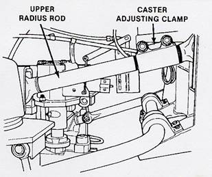
2.2.3 Caster Caster is the longitudinal forward or backward tilt of the kingpin relative to the vertical (perpendicular) centerline of the tire (see Figure 2). Positive caster is the inclination of the kingpins toward the rear of the vehicle, while negative caster is the inclination of the kingpins toward the front of the vehicle. Caster essentially controls where the steering load falls relative to the centerline of the tire. Positive caster indicates that the effective steering input point at the wheel is just in front of the center of the wheel, whereas negative caster indicates that the wheels are being steered from a point just in back of the center of the wheel. With respect to tire wear and fuel economy, caster is the least crucial element of alignment. However, caster has a profound impact on vehicle stability and handling. Modern trucks are designed to include some degree of positive caster. This causes the left front wheel to lift the vehicle slightly when the wheels are turned left, and the right front wheel to lift the vehicle during a right turn (an effect similar to that produced by an anti-sway bar on the rear of a vehicle). Positive caster and the weight of the vehicle combine to keep the front wheels pointing straight ahead as the vehicle is going down the road, thus increasing stability. Improper caster is frequently at the root of driver complaints of wandering and pulling. Variations will also cause wheel shimmy and difficulty steering through curves. Improper caster at both front wheels often causes wandering, whereas one front wheel having more or less caster than the other can cause pulling. A bent axle, worn suspension bushings, and/or excessive loading of the front axles can cause caster variations. Caster is adjustable on many (but not all) modern heavy-duty vehicles. Caster can be adjusted by varying the effective length of the upper radius rod on many vehicles (see Figure 3). By adjusting the upper radius rod, the orientation (or rotation) of the axle is effectively changed. As with toe and camber, real-time or continuous (dynamic) adjustment of the caster may be possible, but a major redesign of the front suspension geometry would be required. 2.3 Total Vehicle Alignment It is important to note that the 'total vehicle' should be properly aligned, not just the front axle. Industry experts generally agree that alignment of the drive axles in a tandem configuration is also critically important for the vehicle to achieve proper tracking. There are two basic ways that drive axles can be misaligned. In one case, if both axles are parallel but are not perpendicular to the vehicle centerline, then a resultant "thrust" angle is created. As shown in Figure 4, the drive axles try to push the vehicle away from the centerline. If the drive axles are not parallel, then the situation is described as a "scrub" angle problem. In this case, the drive axles are trying to turn the vehicle. In either case, to bring the truck's travel back into a straight line, the driver has to provide an opposing steering input. This need for continual correction can induce driver muscular fatigue, as well as increased tire wear and reduced fuel economy. 
Figure 4. Tractor-Trailer Misalignment Conditions
Trailer alignment is also critically important, and the Technology and Maintenance Council (TMC) recently updated procedures for aligning trailers in Recommended Practice (RP) 708. Trailer misalignment will also cause increased tire wear, increased aerodynamic drag, reduced stability, and reduced fuel economy Essentially, trailer alignment involves adjusting all components in such a way that the trailer tracks straight and true, and is a matter of adjusting how trailer components line up according to three parameters-axle orientation, axle toe, and axle camber. While trailer wheels can be out of alignment relative to camber and/or toe, according to some industry experts, the most common problem is axle offset. Axle offset, or 'dog-tracking,' is when the rear of the trailer is displaced to one side of the tractor when the trailer is being towed. Axle offset is expressed in degrees based on variance with the geometric driving axis, or thrust angle. Thrust angle is the angle between the longitudinal center plane and the geometrical axis. 3. Current State of the PracticeSeveral systems are commercially available to help motor carriers and others who maintain CMVs align the tractor and trailer. Most systems rely on laser-based optical systems and computer-assisted measuring methods. While there are differences among the various systems, they all are based on detecting and measuring the same thing-deviation from the horizontal, vertical, parallel, and perpendicular axes. All of these systems measure the alignment of a vehicle in a static condition; that is, alignment measurements and adjustments are performed in a shop, on a turntable or rack. Numerous companies market alignment systems. (See the Appendix for a listing of companies offering vehicle alignment products and systems.) In addition, truck and bus OEMs use sophisticated tooling and fixtures during factory assembly processes to assist with improving alignment accuracy. For example, MeriLab Corporation distributes factory alignment systems that allow alignment to be checked and adjusted while the vehicle is being operated on a heavy-duty dynamometer (although no load is placed on the vehicle that would simulate a trailer load). A few companies have studied specific aspects of dynamic alignment, but there has been no detailed study on dynamic alignment of tractor-trailer combination vehicles. Meritor Automotive and Bee Line have developed some mechanisms for studying dynamic toe, but have not addressed other alignment measurements (including axle camber and axle offset). Correvit (marketed by Datron) makes a variety of advanced optical sensors that appear to be adaptable for trucks that are capable of measuring caster, camber, slip angle, and parallelism. In May 1999, TMC published target values for various alignment measurements including toe, camber, and caster (RP 708). These targets were based on dozens of empirical studies and on historical data collected from trucking companies correlating alignment settings with tire life and/or stability and handling. (Before this date, there were only recommended ranges of values to be used for various loading conditions.) Although these 'static' settings are believed to be the best available figures, different load, speed, and driving conditions have proven to have significant impacts on the alignment, and thus on tire wear and on vehicle stability and handling. In addition, a certain amount of 'settling' occurs on a vehicle (particularly when new) due to changes in springs, bushings, and painted parts. The currently available alignment settings are, therefore, still questionable because there is little scientific evidence to support that they are the 'optimum' settings under dynamic or real-world driving conditions. It should be noted that TMC also published RP 642, Total Vehicle Alignment: Recommendations for Maximizing Tire and Alignment-Related Component Life, which further describes methods for proper alignment of commercial vehicles. Truck builders, drive train suppliers, major tire makers and re-treaders, major suspension manufacturers, and alignment equipment makers developed RP 642 cooperatively. Its stated purpose is to provide 'procedures to identify, record, document, and analyze instances in which vehicle components or manufacturing processes fail to meet user expectations.' It also offers guidelines for selecting and evaluating both alignment equipment and service providers. Research related to dynamic vehicle alignment might follow two generalized approaches: - Evaluate static alignment settings under various conditions
- Implement onboard "dynamic" alignment capability
4.1 Research Approach 1: Evaluate Static Alignment Settings This research approach would focus on determining "optimal" static alignment settings and might consist of the following tasks. - A new tractor-trailer (perhaps a "premium" model) would be instrumented with a variety of sensors to monitor the effects of poor alignment. Poor alignment can manifest itself in a number of ways including:
- Increased vibration in various suspension components
- The need for steering input from the driver to keep the vehicle going straight (either intermittent inputs that would normally not be needed or continuous inputs)
- Increased stress in various suspension, chassis, and frame members that carry loads (particularly the kingpin, tie rods, control arms, and steering linkage)
- Increased lateral loads on wheel ends and tires
- Increased (and highly directional) loads on the fifth wheel
- Increased load on the engine-and associated impacts on fuel economy
- Vehicle instrumentation would thus be designed to monitor the above components and systems during various driving situations. Instrumentation would likely consist of:
- Accelerometers placed in several locations on the chassis and frame to measure high-frequency vibrations
- Strain gauges affixed to various chassis and suspension components to measure changes in load-bearing forces
- Thermocouples on various components to identify any heating effects that might be induced by high forces or vibration
- Strain gauges located on axles and wheel ends to measure unusual lateral forces
- Steering linkage load sensors
- Data loggers to precisely measure power output and fuel economy under "instantaneous" conditions
In addition to the above sensors that measure the consequences (or results) of poor alignment, it may also be possible to directly measure alignment settings under dynamic conditions. Companies such as Datron (Correvit) offer highly accurate laser-based measurement systems that are designed to be affixed to vehicles and operate under "real-world" test conditions. The systems can precisely measure very small changes in angles, distances between reference points, and rotation between components using sophisticated laser "targeting" methods. (See www.Datron.com.) - The test vehicle (tractor and trailer) would first be aligned using factory-recommended settings. The vehicle would then be operated under various load, speed, grade, road curvature, and road crown conditions. The output from the various sensors would be recorded to establish the "baseline" strains, stresses, and loads when the vehicle was properly aligned.
- Next, the vehicle's alignment settings would be altered (one at a time), and the road testing sequence would be repeated. The output of the sensors could then be compared with baseline performance. If vibration, stresses, and/or steering loads increased, then the change in alignment settings was sub-optimal. However, if the instrumentation showed reduced vibration, stresses, and steering input (on average across the various test conditions), then the changes to the alignment would establish a new "baseline" performance target. This process would be repeated to determine the settings that are truly optimal across several dynamic conditions.
The above research plan faces a number of challenges, including the following. 4.1.1 Instrumentation The selection and installation of "conventional" sensors (such as strain gauges, thermocouples, and accelerometers) would be a significant challenge. Since this type of work has not been done before, determining the proper location and orientation of sensors on various components would likely be an iterative (and time-consuming) process. The actual selection of sensors to ensure appropriate size, accuracy, and resolution requirements would also be a significant subtask-as would calibration of sensors after installation. An additional challenge would be tailoring the apparatus, hardware, and software needed for installing laser-based systems capable of directly measuring alignment settings. Our investigation reveals that this type of work has been done on light-duty vehicles (usually in connection with trying to improve alignment for racing vehicles), but has not been done for heavy-duty vehicles. 4.1.2 On-Road Test Matrix Several road surfaces with varying crown, grade, and curvature conditions would need to be identified-and an efficient test matrix developed. The work would also have to be done in a safe setting. Some of the testing might have to be done on public roads and some on a test track. Identifying the appropriate road surfaces and developing the test matrix would be a significant logistical challenge. 4.1.3 Variations in Vehicle Design and Manufacture It is understood that suspension, chassis, steering system, and axle designs vary considerably between manufacturers and truck types (see Figure 5). These variations mean that conclusions regarding alignment settings from the test vehicle may not be fully applicable to vehicles from other manufacturers. The manner (or degree) to which various speed and load conditions impact suspension system flexing and movement is almost certainly different for different
designs-and therefore the alignment information gained on the test vehicle may not be "universal." 
Figure 5. Various Heavy-Duty Suspension Designs
It is also recognized that there is a certain degree of production variability in any particular truck line or model. This is due both to assembly tolerances as well as differences in incoming components. Therefore, it is possible that the "optimal" alignment settings developed during the research study would only be applicable to the specific vehicle chosen for the test. In effect, the research work would have resulted in a "tweaking" of the settings for a particular vehicle (not unlike "blueprinting" a particular engine for a racing application). Both of these issues (design difference between truck models, and production differences within a model line) could be addressed effectively by testing more trucks (perhaps selecting three different truck models and testing three samples of each model), but the magnitude of such a research program would be quite large. 4.2 Research Approach 2: Implement Onboard "Dynamic" Alignment Capability As discussed, most truck designs today allow for manual adjustment of front-end toe and caster, whereas camber is most often fixed by kingpin orientation and design. Drive axle alignment is also fixed at the factory. Adjustments can be made to axle orientation to ensure parallelism-but only with significant effort (unbolting, adjusting, and re-fastening the entire axle to the chassis). Axle alignment on trailers is also fixed at the factory; however, again, adjustments can only be made with difficulty. In all cases, there are currently no provisions for dynamically changing any of these alignment settings-on any axles. We have not been able to identify any hardware or systems (experimental or otherwise) that would enable such capability. Therefore, the capability would have to be invented. It is possible that research related to dynamic alignment, and/or rigorous examination of current static alignment procedures and settings, could have substantial payoffs and wide implications for the trucking industry. At one end of the spectrum, insights gained could lead to changes in the design of suspension systems, alignment mechanisms, or even entire truck frames. The output of the work might be used to tailor or modify static alignment settings (if current settings are found to be sub-optimal) to yield better overall vehicle performance (e.g., handling, vibration, steering effort) under actual on-road conditions. At the other end of the spectrum, the analyses may reveal that the industry's current knowledge represents optimal settings for vehicle alignment. In any case, this research would shed valuable light on a little studied yet vitally important area of truck maintenance. Additional benefits of a tractor-trailer dynamic alignment research program would include: - Gaining a better understanding of how long tires can actually last under a variety of conditions. It has been shown that tires can last up to 150,000 miles; however, some industry experts believe that this limit could be even higher if more information were known about the dynamic nature of alignment.
- Determining the effect, if any, of enhanced total vehicle alignment (under dynamic conditions) on vehicle stability and handling characteristics-and therefore safety.
- Providing information to truck, tractor, and trailer OEMs, as well as designers and suppliers of suspension systems, chassis components, and steering systems, regarding possible design changes to improve vehicle performance.
It also is important to note that tractor-trailer alignment issues and designs do not fall clearly in the domain (or area of responsibility) of any single group of industry stakeholders or suppliers. To this extent, alignment issues always seem to be "someone else's problem." Suspension designers and axle suppliers clearly play a major role in component design. But truck OEMs have responsibility for "putting it all together" and ensuring components are properly integrated when the vehicle leaves the factory. Vehicle OEMs will claim, however, that it is the fleet owner's responsibility to check and adjust alignment as needed throughout the life of the vehicle. Tire OEMs, trailer manufacturers, and brake suppliers also have a stake in the alignment issue. Because there are many responsible parties, no single industry stakeholder has been willing or able to justify and fund comprehensive research related to total vehicle alignment. To this extent, pre-competitive, jointly sponsored research in this area of vehicle design would appear to be justified-particularly since alignment can have a direct impact on safety and fuel economy. The challenge will be to conduct such research in a cost-effective manner. Tractor-trailer alignment is a complex issue, and any research program will likely be comparatively complex, requiring specialized instrumentation, multiple vehicle platforms, a diverse and safe testing environment, and, most importantly, the involvement of experts from several disciplines and suppliers within the trucking industry.
Appendix: Sample Vehicle Alignment Products and Services The vehicle alignment systems listed on the following pages are representative of systems available in the commercial vehicle marketplace. The information was obtained from the manufacturers, and is not meant to be comprehensive or to imply any endorsement or qualification of the particular companies or products listed. A table listing companies supplying vehicle alignment equipment and/or services follows the sample products. MeriLab Corporation www.merilab.com Model 510 Non-Contact Aligner 
The Model 510 Aligner features non-contact alignment (NCA) laser technology to measure alignment variables. The NCA system is a rapid and repeatable way to geometrically measure and set the wheel alignment of cars and trucks. This system projects laser beams onto the sidewall of the tire, vision sensors detect the laser images, and the system interprets these images to calculate wheel toe and camber. Because there are few moving parts and no direct contact between the NCA system and the vehicle, the maintenance of this system is minimal. Additional features of the Model 510 Aligner include: - Roller support base where each wheel of the vehicle is supported by a roller module that employs self-motored rollers and massive roller support balls for durability
- Free-floating roller module to accommodate individual wheelbase variation and steering characteristics
- Maximum operator access, which can easily accommodate automatic tooling within the workspace
- Design incorporates safety, ergonomics, ease of maintenance, and years of trouble-free operation
Model 970 Dynamic Aligner 
The Model 970 Aligner features the patented Dynamic method to measure wheel alignment parameters. This method measures wheel alignment based on how the vehicle will travel on the road. Its innovative roller modules are servo-driven in the toe and camber planes to ensure that the aligner is not placing any extraneous forces on the vehicle's suspension. The Dynamic system evaluates the displacement that the turning wheels cause on the rollers and continually converts the data into toe and camber measurements. This allows an operator to rapidly set the vehicle's alignment. In addition, the dynamic system is: - Easy to operate and maintain
- Very sensitive and accurate yet unaffected by common process variation problems
- Designed to provide a completely force-free environment for the vehicles' wheels during tire run-out evaluation and correction, resulting in an optimum alignment environment for the vehicle
CORRSYS-DATRON http://www.corrsys-daytron.com/ Non-Contact Optical Sensors  CORRSYS-DATRON non-contact optical sensors represent the ultimate refinement in the evolution of measurement technology. Since the introduction of the world's first optical speed and distance sensor in 1981, CORRSYS-DATRON has worked continually to bring increasingly high levels of accuracy and repeatability to the measurement of dynamic variables including speed, distance, angle, and height. CORRSYS-DATRON non-contact optical sensors represent the ultimate refinement in the evolution of measurement technology. Since the introduction of the world's first optical speed and distance sensor in 1981, CORRSYS-DATRON has worked continually to bring increasingly high levels of accuracy and repeatability to the measurement of dynamic variables including speed, distance, angle, and height.
In the arena of dynamic vehicle testing, CORRSYS-DATRON non-contact optical sensors have become the standard for measurement of vehicle handling and performance characteristics. Far surpassing the accuracy and reliability of the fifth wheel, CORRSYS-DATRON non-contact optical sensors are easier to set-up and easier to use. And because they do not make contact with road or track surfaces and have no moving parts, they resist damage and wear in even the most punishing testing applications.
In addition to their use in vehicle testing, CORRSYS-DATRON non-contact optical sensors also prove to be highly effective for the measurement and control of rail vehicle speed, aerospace testing, industrial process measurement and consumer product testing. They are also ideally suited to a multitude of other applications demanding exceptional accuracy and rugged reliability. Goodyear Goodyear provides an excellent overview of "Total Vehicle Alignment" for commercial vehicles at http://www.goodyear.com/truck/pdf/radialretserv/Retread_S6_V.pdf AlTech Industries http://www.atindustries.com/ "Conventional" CV Alignment Systems The HDT-6 Alignment System was designed for all large dual rear wheel trucks such as semi tractors with single or tandem rear axles, buses, motor homes, and delivery trucks. The HDT-6 allows total vehicle alignment by aligning the rear axles with the steering axle at the same time. Check out the unique features of the HDT-6 System. 
The HDT-6 system measures: - Total toe and toe at each wheel
- Thrustline at the rear axles
- Off-center axles
- Setback on the steer axle
- Wheelbase
- Camber
- Caster
- King pin inclination (KPI)
The HDT-6 can be used in all truck shops in every stall. A dedicated alignment stall for alignment diagnosis is not required. The system can also be used off-site to diagnose vehicles at a customer fleet parking lot, truck stops, RV lot, or anywhere on the road. The HDT-6 Alignment System consists of: - 6 Diagnostic Wheel Fixtures (16' to 26.5' rims)
- Digital Electronic Level (9 volt)
- Steering Wheel Holder
- Storage Cart
- Instruction Manual
- Diagnostic Worksheets
Companies Supplying Vehicle Alignment Equipment and/or Services AMERMAC INC. PO Box 386 Ellaville, GA 31806 800-841-8065/FAX: 912-937-2894 | AUTOMOTIVE DIAGNOSTICS 8001 Angling Rd. Kalamazoo, MI 49002 616-329-7600/800-358-2400 FAX: 616-329-7714 http://www.adspx.com "CCD Series Bear" | AXLE-TRU INC. PO Box 223 Columbia City, IN 46725 219-244-5046/800-879-5599 FAX: 219-244-4383 | JOHN BEAN CO. Industrial Park Conway, AR 72032 501-450-1500/800-362-8326 FAX: 501-450-1585 | BEE LINE CO. 2700-62 St. Ct. Bettendorf, IA 52722 319-332-4066/800-728-7828 FAX: 319-332-6517 www.beeline-co.com | JH BENDER EQUIPMENT CO. 5430 Tweedy Blvd. South Gate, CA 90280 213-566-3169/800-423-7530 FAX: 213-566-2271 | BLACKHAWK/KJ HD Div. of Hein Werner Corp. PO Box 1606 Waukesha, WI 53187-1606 414-542-3010/800-558-4206 FAX: 414-542-3622 "AR165, King Power Post" "Power Cage, TTLA" | DETROIT AUTOBODY EQUIPMENT INC. 200-B S Main St. Northville, MI 48167 313-416-6204/FAX: 313-416-6211 "Floor Pots, Framemaster System" | HAMILTON TEST SYSTEMS 2002 N. Forbes Blvd. Tucson, AZ 85745 602-620-1500 | HARTMANN MANAGEMENT SERVICES (HMS) 312 W. Main St. Barrington, IL 60010 312-382-4010/800-358-2736 FAX: 312-381-6894 | HENNESSY INDUSTRIES INC. 1601 JP Hennessy Dr. Lavergne, TN 37086 615-641-7533/800-688-6359 FAX: 800-688-3659 "AMMCO" | HUNTER ENGINEERING CO. 11250 Hunter Dr. Bridgeton, MO 63044-9997 314-731-3020/800448-6848 FAX: 314-731-0132 | JOSAM PRODUCTS INC. 8849 Exchange Dr. Orlando, FL 32809 407-438-7020/FAX: 407-438-9281 | MAC TOOLS INC. PO Box 32940 Columbus, OH 43232-0940 614-755-7000/FAX: 614-755-7139 (Tools only) | M.D. ALIGNMENT SERVICE PO Box 187 Altoona, IA 50009 800-617-5592/FAX: 515-987-0448 mdalign@aol.com http://www.ioweb.com/mdalign "Protrak" | MYERS TIRE SUPPLY CO. 1293 S. Main St. Akron, OH 44301 216-253-5592/800-998-9897 FAX: 216-253-1882 | OMER USA INC. 1413 Sherman Rd. 40 Romeoville, IL 60441 708-972-0883/800-336-6637 FAX: 708-972-9477 | OTC - Div of SPX Corp. 655 Eisenhower Dr. Owatonna, MN 55060 800-533-6127/FAX: 800-283-8665 http://www.otctools.com | ROTARY LIFT 2700 Lanier Dr. Madison, IN 47250 812-273-1622/800-445-5438 FAX: 812-273-6502 | S&G TOOL AID CORP. 43 E. Alpine St. Newark, NJ 07114 201-824-7730/800-888-2080 FAX: 201-621-7132 | SNAP-ON INC. 2801 80th St. Kenosha, WI 53140-1410 414-656-5200/FAX: 414-656-4980 | SPX CORP. 700 Terrace Point Dr. Muskegon, MI 49443-3301 616-724-5000/FAX: 616-724-5720 | SPECIALTY PRODUCTS CO. 4045 Specialty Pl. PO Box 923 Longmont, CO 80502-0923 303-772-2103/800-448-2524 FAX: 303-772-1918 | SWEENEY MFG. - Div. Dover Diversified 359 Inverness Dr. S., Ste. B Englewood, CO 80112 303-792-5240/800-448-2524 FAX: 303-792-5124 "Bazooka" |

|
|
|