Posts Tagged ‘historical photos’

Slice of History: Viking Stereo Viewer

Tuesday, December 4th, 2012

By Julie Cooper

Each month in “Slice of History” we feature a historical photo from the JPL Archives. See more historical photos and explore the JPL Archives at https://beacon.jpl.nasa.gov/.

Viking Stereo Viewer
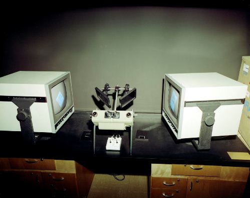
Viking Stereo Viewer — Photograph Number 324-1954

This interactive computer-based stereo viewing system was used to analyze Mars topography images generated by the cameras on NASA’s Viking 1 Mars lander. Two 17-inch video monitors faced a scanning stereoscope mounted between them on a table. Left and right lander camera image data were sent to the left and right monitors. Panning controls on the stereoscope helped align one image with the other to create a stereo image, 640 by 512 pixels in size. A mouse was used for finely controlled rotation of the monitors. An article about the system described a prototype mouse, used before this photo was taken in 1976. “The track ball is a baseball-sized sphere protruding from the top of a retaining box and capable of being rotated freely and indefinitely about its center …”

The resulting images could be displayed on additional monitors and were used to create contour maps and other images that aided lander surface operations. The system was developed by Stanford University and NASA’s Jet Propulsion Laboratory in Pasadena, Calif.

This post was written for “Historical Photo of the Month,” a blog by Julie Cooper of JPL’s Library and Archives Group.


Slice of History: Surveyor 3 Camera Returned from the Moon

Tuesday, January 24th, 2012

By Julie Cooper

Each month in “Slice of History” we feature a historical photo from the JPL Archives. See more historical photos and explore the JPL Archives at https://beacon.jpl.nasa.gov/.

ASurveyor 3 Camera Returned from the Moon
Surveyor 3 Camera Returned from the Moon — Photograph Number P-10709B

In November 1969 Apollo 12 astronauts Alan Bean and Pete Conrad landed on the moon less than 600 feet from NASA’s Surveyor 3 spacecraft, which had been there since April 1967. They removed the camera, some cable and tubing, and the trenching scoop from the lander and brought them back to Earth so that the effects of prolonged lunar exposure could be studied by Hughes Aircraft Company (the spacecraft prime contractor) and NASA’s Jet Propulsion Laboratory. The Surveyor 3 camera was kept under quarantine and studied for several weeks at the Lunar Receiving Laboratory in Houston. Then it was shipped to the Hughes facility in Culver City, Calif. This photo was taken in January 1970, probably at the Hughes facility, where Hughes and JPL employees photographed, disassembled and studied the camera in detail.

This post was written for “Historical Photo of the Month,” a blog by Julie Cooper of JPL’s Library and Archives Group.


Slice of History: Freeway Tunnel Simulator

Thursday, October 6th, 2011

By Julie Cooper

Each month in “Slice of History” we feature a historical photo from the JPL Archives. See more historical photos and explore the JPL Archives at https://beacon.jpl.nasa.gov/.

Freeway tunnel simulator
Freeway Tunnel Simulator — Photograph Number P-20673A

In October 1978, this photo was taken of a freeway tunnel simulator, which was used to study the air quality in freeways that were partly covered by buildings, streets or parks in an urban area. The Highway Intermittent Tunnel Simulator (HITS) project was carried out at NASA’s Jet Propulsion Laboratory under a contract with the Federal Highway Administration, Department of Transportation. A series of reports from this project were written to assist highway planning and design.

The simulator used electric motors to power two adjustable speed belts traveling in opposite directions, with 75 scale model automobiles attached. They could travel at about 40 “mph” (to scale) along a 110-foot straightaway. A gas was introduced into the tunnels to simulate exhaust fumes. Concentration and dispersion of the gas were measured as the automobiles moved through the tunnels. Test parameters such as distance between openings, type of traffic dividers and traffic speed were varied to see how they affected the air flow patterns.

At left is Bain Dayman, the HITS project manager. At right are Howard Jongedyk, FHA contract manager; Curtis Tucker, facility design engineer; and Robert Baxter, a contractor with AeroVironment, Inc., Pasadena. Most of the people working on this project were part of the Civil Systems Engineering Section at JPL.

This post was written for “Historical Photo of the Month,” a blog by Julie Cooper of JPL’s Library and Archives Group.


Slice of History: Cookie Cutter Missile Propellant

Wednesday, September 7th, 2011

By Julie Cooper

Each month in “Slice of History” we feature a historical photo from the JPL Archives. See more historical photos and explore the JPL Archives at https://beacon.jpl.nasa.gov/.

Cookie Cutter Missile Propellant
Cookie Cutter Missile Propellant — Photograph Number 381-490

The ORDCIT Project at NASA’s Jet Propulsion Laboratory was a research and development program about long-range jet propelled missiles. Under a contract with the Army’s Ordnance Department, a series of solid propellants were developed and tested. This photo shows a neoprene based formula referred to as ORDCIT 29, created in 1945.

Ingredients were mixed and formed into a sheet using a small roller mill. The uncured sheet was laid on a table and cut into disks, using a tool that looked like a large cookie cutter. The disks were stacked and wrapped in a neoprene liner. This cylinder was then placed in a mold and compressed. The locked mold was placed in an oven at high temperatures to vulcanize the charge and fuse the propellant and liner into one solid piece.

Twenty-one of these restricted-burning solid propellant cartridges were tested at various temperatures and various chamber pressures. The results were promising, and Progress Report No. 4-25 recommended more extensive testing.

This post was written for “Historical Photo of the Month,” a blog by Julie Cooper of JPL’s Library and Archives Group.


Slice of History: Anechoic Chamber

Wednesday, June 8th, 2011

By Julie Cooper

Each month in “Slice of History” we’ll be featuring a historical photo from the JPL Archives. See more historical photos and explore the JPL Archives at https://beacon.jpl.nasa.gov/.

Anechoic Chamber
Anechoic Chamber — Photograph Number 383-5765Ac

This aerodynamic noise facility, also called an anechoic chamber, was used to study the noise generating mechanisms in supersonic and subsonic jets in the early 1970s. It was housed at NASA’s Jet Propulsion Laboratory in building 57 (which no longer exists) located next door to the wind tunnel that was in building 79 at the time. The large round opening in the wall is an exhaust silencer inlet. Standing next to it is Paul Massier, co-author of a technical report about this chamber. On the right is a support structure for microphones. Fiberglass wedge blocks cover the ceiling and walls, which were mostly reinforced concrete. Spaces were left open to allow for observation windows and instruments to record test data. There were also openings in the walls that allowed air to flow into the chamber to replace the air forced out during tests.

This post was written for “Historical Photo of the Month,” a blog by Julie Cooper of JPL’s Library and Archives Group.


Slice of History: Low Temperature Propellant Tests

Monday, May 16th, 2011

By Julie Cooper

Each month in “Slice of History” we’ll be featuring a historical photo from the JPL Archives. See more historical photos and explore the JPL Archives at https://beacon.jpl.nasa.gov/.

liquid propellant jet
Low Temperature Propellant Tests — Photograph Number 6-8

It was 1943 and JPL was at the beginning stages of rocket motor research and development.  Over the next decades, JPL would design and test rocket motors with a variety of sizes and propellants.  This small (50 pound thrust) liquid propellant jet unit was immersed in a bath of ice and salt in order to test the ignition properties of the propellants at temperatures near 0°F. 

This post was written for “Historical Photo of the Month,” a blog by Julie Cooper of JPL’s Library and Archives Group.


Slice of History: Ranger Midcourse Motor

Monday, April 4th, 2011

By Julie Cooper

Each month in “Slice of History” we’ll be featuring a historical photo from the JPL Archives. See more historical photos and explore the JPL Archives at https://beacon.jpl.nasa.gov/.

Ranger Midcourse Motor
Ranger Midcourse Motor — Photograph Number 384-5117B

Engineer Ted Metz proudly showed off the Ranger midcourse correction motor in a photo similar to this one that appeared in the May 1965 issue of Lab-Oratory, the JPL employee newsletter. “Since few Lab employees have seen the Ranger and Mariner midcourse propulsion unit, we show here the rocket motor portion of the system held by Propulsion project engineer, Ted Metz. This 50-pound thrust motor utilizes hydrazine fuel and has successfully corrected the trajectories of the Mariner R, Mariner IV and Rangers VI through IX spacecrafts.”

From 1961 to 1965, there were six Ranger flights that failed for various reasons and three very successful ones (Rangers 7, 8, and 9). Mariner R (based on the Ranger spacecraft, also called Mariner 2) had flown by Venus, and Mariner 4 was on the way to Mars.

This post was written for “Historical Photo of the Month,” a blog by Julie Cooper of JPL’s Library and Archives Group.


Slice of History: Transition Pipe

Friday, March 4th, 2011

By Julie Cooper

Each month in “Slice of History” we’ll be featuring a historical photo from the JPL Archives. See more historical photos and explore the JPL Archives at https://beacon.jpl.nasa.gov/.

Transition Pipe
Transition Pipe — Photograph Number 327-287A

This test setup was part of an investigation in 1954 of the stability of laminar pipe flow with respect to disturbances of different frequencies and amplitudes. A disturbance generator was developed using vibrating aluminum reeds and instruments measured how a small amplitude disturbance in the air flow changed as it propagated down the 115–foot length of a 2” aluminum pipe. It appears to be located in the concrete channel that was used in the 1940s as a hydrodynamic tank with a rocket-propelled towing car (the “Hydrobomb”). At the end of the room you can see metal rungs that were used to climb down into the channel when the water was drained.


This post was written for “Historical Photo of the Month,” a blog by Julie Cooper of JPL’s Library and Archives Group.