|
Chemistry & Mineralogy (CheMin)
PI: David Blake, NASA Ames Research Center
Contributions of CheMin to MSL Science Objectives
An important science goal of the MSL mission is to identify and characterize past or present habitable environments as recorded in sediments and rocks. CheMin is a definitive mineralogy instrument that will identify and quantify the minerals present in rocks and soil delivered to it by the Sample Acquisition, Sample Processing and Handling (SA/SPaH) system. By determining the mineralogy of rocks and soils, CheMin will assess the involvement of water in their formation, deposition, or alteration. In addition, CheMin data will be useful in the search for potential mineral biosignatures, energy sources for life or indicators of past habitable environments. CheMin can unequivocally identify and quantify minerals above its detection limits in complex natural samples such as basalts, multicomponent evaporite systems, and soils.
Instrument Description
CheMin, short for “Chemistry and Mineralogy,” is a powder X-ray Diffraction (XRD) instrument that also has X-ray Fluorescence (XRF) capabilities. CheMin is part of the Analytical Laboratory of the MSL rover, which is located inside the main body of the rover. CheMin will analyze as many as 74 samples delivered by the SA/SPaH system during the nominal prime mission, but is capable of analyzing many more because its sample cells can be reused for additional analyses. Each analysis may take up to 10 hours of analysis time, spread out over two or more Martian nights, although some samples may provide acceptable results in a single sol. CheMin utilizes a microfocus cobalt X-ray source, a transmission sample cell, and an energy-discriminating X-ray sensitive CCD to produce simultaneous 2-D X-ray diffraction patterns and energy-dispersive histograms from powdered samples. Raw CCD frames are processed into data products onboard the rover to reduce the data volume. These data products are transmitted to Earth for further processing and analyses.
Measurement Description
In operation, a collimated X-ray beam from the X-ray tube is directed through a transmission sample cell containing powdered material prepared and delivered by the SA/SPaH system. An X-ray sensitive CCD imager is positioned on the opposite side of the sample from the source and directly detects X-rays diffracted or fluoresced by the sample. The CCD detector is operated in single-photon counting mode (the detector is read out at a frequency that ensures that the vast majority of pixels contain charge from either zero or one photon). The CCD detector is exposed to the X-ray flux, read out and erased a large number of times for each analysis (1000 or more exposures). When operated in this manner, the CCD can be used to measure the charge generated by each photon (and hence its energy). Diffracted X-rays strike the detector and are identified by their energy, producing a two-dimensional image that constitutes the diffraction pattern. All of the X-rays detected by the CCD are summed into a histogram of number of photons vs. photon energy that constitutes an energy-dispersive X-ray histogram of the sample. A cartoon of the CheMin geometry is shown in the figure below. At incremental radii the two-dimensional pattern is summed circumferentially about the central undiffracted beam (ground processing) to yield a one-dimensional 2-theta plot comparable to conventional diffractometer data. Quantitative mineralogical results are obtained from XRD data by Rietveld refinement, FULLPAT and other full-pattern fitting techniques. Both crystalline and amorphous materials can be analyzed in this fashion.

Geometry of the CheMin instrument. (left) Overall geometry of CheMin; (above right) XRD 2-theta plot obtained by summing diffracted photons from either of the characteristic lines of the X-ray source (Co K-alpha is colored magenta); (below right) X-ray energy-dispersive histogram obtained by summing all of the X-ray photons detected by the CCD (fluoresced photons from the sample shown schematically for elements Fe and lighter).
CheMin Science Requirements
The original Project-level science requirements statement is: “The Project System will be able to utilize the X-ray diffraction (XRD) and X-ray fluorescence (XRF) capabilities of CheMin to establish the mineralogy and elemental composition of rocks and soils, inferring the formation and alteration histories of samples acquired by the mission.” This requirement was amended when the Si-PIN diode for reflection-geometry XRF was descoped from the proposed design. Quantitative XRF analysis of elemental composition is now only a “best effort” task dependent on progress in element quantification using only the transmission geometry. The critical components of the initial requirement are still supported, because CheMin will still use the CCD energy-dispersive histogram capability to aid in mineral identification and analysis. Specific measurement objectives are as follows:
XRD detection limits. The CheMin instrument shall be able to detect individual minerals in complex mixtures that are present at the 3% level and above.
XRD accuracy. For minerals that are present in concentrations of 12% and above (4 times the minimum detection level, 4 x MDL), CheMin shall be able to state the absolute amount present ±15%. For example, a mineral present in 12% concentration shall be quantifiable as 12%±1.8%. Reaching the goals for accuracy and precision will depend on whether the grain flow in the cell during measurement can be improved.
XRD precision. The goal for precision of a reported mineral concentration, when present in quantities greater than 4 x MDL, is ±10%.
XRF detection limits, accuracy and precision. As stated above, XRF requirements have been descoped from the instrument, and are now on a "best efforts" basis. CheMin will return XRF data in the form of energy-dispersive X-ray histograms with a Full Width Half Maximum (FWHM) of 250 eV or better measured at the position of Fe K-alpha (6.4 keV). As a result of the transmission geometry and the presence of a Mylar or Kapton window between the sample and the detector, CheMin will only detect elements with an atomic number greater than 12 (Mg) in the periodic table.
CheMin Instrument Operation
The CheMin sample handling system consists of a funnel, a sample wheel (which carries 27 reusable sample cells and 5 permanent reference standards), and a sample sump where material is dumped after analysis. CheMin receives drill powders or scoop samples from the SA/SPaH (Sample Acquisition/Sample Processing and Handling) system, through the drill, scoop, and CHIMRA sorting assembly. A maximum of 65 mm^3 of sample material is delivered to the piezoelectrically vibrated funnel system that penetrates through the rover deck (during the time period when CheMin is not receiving samples, the CheMin inlet is protected by a cover). The funnel contains a 1-mm mesh screen to keep larger than expected grains from entering the CheMin sample handling system. Grains that cannot pass through the screen will remain there for the duration of the mission (samples will have been prescreened first to 1 mm and then to 150 µm in the CHIMRA sorting chamber, to prevent clogging of the CheMin funnel screen). Any grains between 1.0 mm and 150 µm that pass through the screen will pass into the upper reservoir portion of the sample cell, where they will remain until the cell is inverted and they are dumped into the sump. However, under nominal conditions, the CheMin funnel will only receive material that has passed through the CHIMRA’s 150 µm sieve. For the lifetime of the mission, nominally one Mars year, CheMin is required to accept and analyze material delivered from SA/SPaH with no more than 5% CheMin internal contamination between samples. Self-generated contamination originates from material that has remained in the funnel from previously delivered samples (and delivered along with subsequent samples), or from material that has remained in previously used analysis cells (CheMin will nominally use each reusable cell two to three times to accommodate 74 analyses during the mission). CheMin empties used sample cells by inverting and vibrating the cell and over a sump inside the instrument. CheMin may reduce contamination by sample dilution – aliquots of sample material can either be dumped into the funnel and delivered directly to the sump through a shunt in the wheel without entering a sample cell (to remove funnel contamination), or a previously used sample cell can be filled, shaken and emptied to the sump prior to receiving an aliquot of sample for analysis (to remove sample cell contamination). These processes will require coordination with SA/SPaH to deliver more than one aliquot of a given sample.
A full and complete analysis of an individual sample is called a “major frame” and may require as much as 10 hours of analysis time, at separate times over multiple sols, although some samples will not require such long analysis time and may provide adequate data within a few hours during a single sol. Analyses will be made at night when the CCD can be adequately cooled. Once a major frame of data is sent to ground and accepted, the analyzed material is emptied from the cell and that cell is ready to be reused. CheMin does not have the capability to store previously analyzed samples for later reanalysis.

The Sample Cells and Sample Wheel
The collimated ~50 µm diameter X-ray beam illuminates the center of an 8 mm diameter, 175 µm thick sample cell bounded by 6 µm thick Mylar or somewhat thicker Kapton windows. The sample introduced into the funnel consists of <= 65 mm^3 of powdered material with a grain size of <150 µm. Only about 10 mm^3 of material is required to fill the sample cell, which is a disc-shaped volume with an 8 mm diameter and 175 µm thickness. The remaining sample material occupies a reservoir above the cell. During filling, analysis, and dumping, the sample cell is shaken by piezoelectric actuators (piezos). The modes in which the piezos will be driven are still under test and may vary from sample to sample, depending on such things as grain cohesion (e.g., clay-rich samples versus samples that lack fine particles). Testbeds have used modes in which samples have been vibrated at sonic frequencies (900-2230 Hz). Frequency of the piezo-actuator has been ramped in testbeds so that during a part of the cycle the sample-piezo system is at resonance, at which time the sample exhibits bulk convective movement similar to a liquid, delivering sample grains in random orientation into the volume irradiated by the beam. A nominal resonant frequency of 2150 Hz is characteristic of the tuning forks designed for the MSL CheMin. During the moderate shaking which results in grain convection, it is possible that phase segregation will occur as a result of size or density differences between individual mineral grains. To reduce this problem CheMin can, at intervals depending on the cycle of each individual frame, use episodically larger shaking amplitudes (i.e., “chaos mode”) to homogenize particle size or density segregations in the sample chamber.

Illustration of CheMin dual-cell geometry. Exploded view of dual-cell assembly showing windows, tuning-fork assembly, and piezodriver (left). Assembled cell, ready for testing in testbed (right). The yellow Kapton window is on the left; the clear Mylar window is on the on right.
The CheMin sample cells are constructed in dual-cell “tuning-fork” assemblies with a single horizontally driven piezoelectric actuator in each assembly. A bypass cell allows purge samples to be used to remove prior sample contamination from the inlet funnel; the purge samples are moved directly to the sump after passing through the funnel. Sixteen of the dual-cell assemblies are mounted around the circumference of the sample wheel. Five of the cells will be devoted to carrying standards; the other 27 cells are available for sample analysis and may be reused by dumping samples into the sump after analysis.
Both Mylar- and Kapton-window cells are mounted on the wheel. The two window types have different advantages and weaknesses. Mylar windows have a very flat diffraction background but Mylar is less durable than Kapton under severe vibration and is susceptible to destruction if highly acidic samples (e.g., copiapite) are loaded. Kapton windows are extremely durable under severe vibration and are not susceptible to acid attack, but have a small diffraction contribution at ~6-7° 2-theta which could interfere with the (001) diffraction peak from some clay minerals. Windows of both Kapton (in 13 cells) and Mylar (in 14 cells) are used in the Flight Model (FM) and Development Model (DM). Most of the standard cells use Kapton, but the amphibole standard uses a Mylar window.
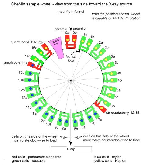
Schematic diagram of the CheMin sample wheel.
Detection of X-ray Photons by the CCD
CheMin will use a 600 × 600 E2V CCD-224 frame transfer imager operated with a 600 × 582 data collection area. The pixels in the array are 40 × 40 µm2, and the active region of deep depleted silicon is 50 µm thick. The front surface passivation layer is thinned over a substantial fraction of the active pixel area. This imager is a modern version of the E2V CCD-22 that was specially built for an X-ray astronomy application. The large size of the individual pixels causes a greater percentage of X-ray photons to dissipate their charge inside a single pixel rather than splitting the charge between pixels. The enhanced deep depletion zone results in improved charge collection efficiency for high energy X-rays. The thin passivation layer makes the CCD sensitive to relatively low-energy X-rays.
In order to keep the CCD from being exposed to photons in the visible energy range (from X-ray induced optical fluorescence) during analysis, a 150 nm Al film supported on a ~2,000-Angstrom polyimide film is placed in front of the detector. The detector itself is cooled to a target temperature of minus 60°C, but the actual CCD temperature will depend on the rover body upper-surface temperature. By cooling the CCD, dark current is eliminated, and the effects of damage to the silicon lattice by neutrons from the Radioisotope Thermoelectric Generator (RTG) and the DAN science instrument will be reduced. Should the temperature not reach minus 60°C for the analysis, the dark current will increase and the neutron damage to the CCD will begin to adversely affect Charge Transfer Efficiency (CTE), resulting in higher background counts and increased full width half maximum (FWHM) in X-ray peaks.
X-ray Diffraction Mode
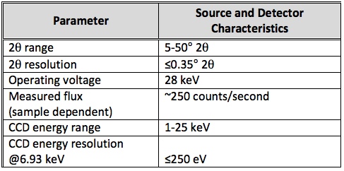
The CCD is placed in the forward-scattered direction relative to the X-ray beam so that mineral phases with large interplanar spacings (and hence narrow diffraction cones of low 2-theta), such as layer silicates, can be detected. In addition, low-index lines (which are commonly the strongest and most definitive for phase identification) lie in the forward-scattered direction. The table shows the expected 2-theta range (for Co K-alpha radiation) and 2-theta FWHM for X-ray diffraction.
Energy-Dispersive Mode: Focus on Characteristic Cobalt Radiation
The CCD-224 directly detects individual X-ray photons that are absorbed by the active silicon, producing a number of electron hole pairs equal to the energy of the X-ray in electron volts, divided by 3.65 (the energy of an electron-hole pair in the silicon lattice). For example, a cobalt K-alpha X-ray with an energy of 6.93 keV will produce 1,899 electron hole pairs. Single pixel events (those representing the absorption of a single photon into a single pixel of the CCD) are summed into a histogram of energy vs. number of counts. This histogram constitutes the energy-dispersive fluorescence spectrum of the sample. The table shows the energy range and resolution.
In its originally proposed configuration, the CheMin geometry was optimized for sample chemical analysis based on energy-dispersive analysis of the fluorescence photons. For this purpose a fluorescence detector was mounted on the tube side of the sample cell, in a reflection geometry similar to that of other instruments (e.g., APXS) where traditional X-ray fluorescence chemical analyses can be obtained by use of fundamental parameters methods. The descope of the reflection geometry detector from the MSL CheMin has removed this capability. However, energy-dispersive capability is still required for discriminating diffracted photons of a specified energy (e.g., Co K-alpha, 6.93 keV) from fluoresced photons (e.g., Fe K-alpha , 6.40 keV) or diffracted photons of other energies (e.g., Co K-beta, 7.65 keV). Although of secondary importance to the energy resolution of primary Co X-rays, qualitative chemical information from secondary X-rays will also be important for supporting mineral identification by pinpointing the chemical constituents to be included or excluded in mineral search/match routines. Future “best effort” characterization, studies may ultimately permit quantification of chemical composition by Monte Carlo methods.
Modes of X-ray Photon Detection for X-ray Diffraction
A special case of X-ray detection by the CCD is the detection of Co K-alpha or Co K-beta characteristic photons from the primary source. When Co K-alpha (or Co-beta) photons are detected, the X,Y pixel location in the CCD is identified and the corresponding X,Y location in a 600x582 counting number array is incremented by one. This process results in a diffraction image. Various strategies are used in on-board data processing to optimize the quality or quantity of diffraction data returned (e.g., "single pixel" detection, and "split pixel" detection).
An additional 600x582 array stores an image of all of the photons detected by the CCD regardless of energy. This array acts very much like a piece of photographic film, recording the XRD pattern as well as background, energy-dispersive data, and Bremsstrahlung.
Calibration Standards
Five permanent cells, in both the FM that goes to Mars and the DM that stays here on Earth, will be loaded with calibration standards. Three of these cells will be loaded with single minerals or a synthetic ceramic and two will be loaded with differing quartz/beryl mixtures. The FM will be loaded with the same five permanent standards as the DM; otherwise the FM will not be exposed to any other materials in open cells before samples are acquired on Mars. The five permanent standards in the DM and FM will be used for cross calibration of the DM following FM calibration.
Basic calibration, completed prior to delivery of the instrument to MSL Assembly, Test, and Launch Operations (ATLO), is performed using only the five permanent standards loaded into the sample cells of the FM. Calibration of these standards will include measurement of 2-theta range and 2-theta FWHM for XRD, and of the required energy range and FWHM for elemental peaks, in particular Fe K-alpha, Co K-alpha, and Co K-beta.
Quantitative XRD Calibration of the Development Model and other CheMin Testbeds
Quantitative X-ray diffraction (QXRD) calibration will be performed using the DM and various testbeds. For QXRD calibration, synthetic mineral mixtures that mimic real samples likely to be encountered on Mars will be carefully prepared from minerals mixed in controlled weight proportions.
For characterization of CheMin operation across a broad spectrum of samples, synthetic and natural, the DM will be supported by a number of testbeds and facilities that replicate various parts of the DM/FM function with varying levels of fidelity. These testbeds and facilities are listed below:
The Development Model (DM): The DM will be set up in a testbed configuration at JPL in CheMin Co-I Albert Yen's laboratory. Prior to launch, the DM will be used to test algorithms, establish calibrations, develop operation scenarios, and characterize Mars analog samples. During landed operations the DM unit will be used to test new sequences, develop operation scenarios, and characterize Mars analog samples.
Analytical facility for Mars analog rocks: This facility at NASA Ames Research Center (ARC) will house several CheMin MSL analog instruments. The principal instruments in this laboratory are an Inel(TM) X-ray diffractometer, a CheMin IV instrument (Bish et al., 2007), and a Terra instrument (a field-deployable instrument developed by InXitu, Inc. (Blake et al., 2008)). These instruments will be used to analyze Mars analog rocks in a geometry similar to the CheMin FM and the DM instruments. The Inel(TM) X-ray diffractometer is configured to analyze Mars analog rocks in a geometry similar to the CheMin flight instrument but with a very different detector. This instrument is equipped with a Co tube and a 120-degree parallel detection system capable of collecting XRD patterns with resolutions in excess of the spacecraft instrument (but which can be degraded to MSL CheMin resolution for comparison and pattern matching). A Mars sample chamber is installed with a carousel and MSL funnel, and a CheMin transmission sample cell capable of being filled, piezo-electrically shaken during analysis and dumped, all under Mars pressure. A large number of patterns of Mars analog rocks and soil will be collected for analysis prior to, during and after the prime MSL mission. The CheMin IV and Terra instruments have the resolution and diffraction geometry of the MSL Flight instrument and will be used in supporting tests.
CheMin IV Testbeds: In addition to the CheMin IV at NASA ARC, three additional CheMin IV testbeds will be established at Co-I facilities, including: JPL (Co-I Albert Yen), Indiana University (Co-I Dave Bish), and NASA Johnson Space Center (Co-Is Doug Ming and Dick Morris). These CheMin IV testbeds will be used to screen samples that are candidates for analysis in the DM.
Calibration of the Flight Model in Mars Operations
In use on Mars, two standards will be analyzed as soon as possible after landing but after analysis of a first contingency sample. The standards to be analyzed are pure amphibole (for energy dispersive histogram calibration) and 97% beryl (for XRD calibration). Subsequent calibrations will be performed using one or more of the permanent standards on a nominal schedule of once every 40 sols.
CheMin Instrument Modes
CheMin will perform integrations in one of two modes. In “calibration mode,” CheMin measures one of five sample cells that contain reference standards in order to calibrate the positions and intensities of peaks in the diffraction pattern and the energy-dispersive histogram. In “sample mode,” CheMin measures material delivered by SA/SPaH and commands can specify integration times as appropriate. In the nominal case, a single < 65 mm^3 aliquot of sample material is delivered to a sample cell and an analysis is initiated. In cases where contamination from previous sample material is suspected either in the funnel or in a previously used sample cell, contamination can be reduced by sample dilution. Contamination reduction in the funnel is accomplished through the use of a sample shunt on the sample wheel. The sample wheel is rotated to the shunt position and the < 65 mm^3 sample is dumped into the funnel during shaking. Sample material incorporates the funnel contamination as it transits through the funnel into the sample shunt. Following this, the shunt is rotated into the “dump” position and the shunt material is deposited in the sump. Contamination reduction in a previously used sample cell is accomplished by filling the cell, vibrating the cell for approximately 10 minutes and dumping the material. A second aliquot of material is delivered to the cell, vibrated for ~10 minutes and dumped. A third aliquot of material is delivered to the cell, and analyzed in the usual way.
During a nominal 10-hour analysis, CheMin collects and stores X-ray data as individual 600 × 582 pixel CCD images of 5-30 seconds exposure each. A “minor frame” nominally consists of ½ hour of these images, or 60-360 frames depending on integration time. A 10 hour analysis of a sample, for example, typically comprises 20 such minor frames and is called a “major frame.” There is insufficient bandwidth to deliver all of CheMin’s raw data to Earth. When commanded, CheMin delivers raw data to the Rover Compute Element (RCE) which in turn partially processes the raw data for each minor frame, in order to reduce the data volume. Each minor frame of data transmitted to Earth contains one or more raw frames in order to assess the health of the detector, a variety of engineering and health information about the instrument, and one or more of four possible processed data products. The four types of data products are described below:
- In "fully processed mode," each image is reduced to a pixel map containing ones and zeros, where "1" represents the detection of a photon within ground-specified high and low energy limits (e.g., Co-K-alpha), and "0" represents everything else. Each pixel map is summed into a 600x582 counting number array of pixel positions; the result is a 2-D energy-filtered diffraction pattern.
- In addition to the energy-filtered diffraction pattern, "fully processed mode" also provides a histogram made of all of the photons detected vs. energy, which amounts to an X-ray energy-dispersive spectrum of the sample material.
- In "film mode," images are summed into a 600x582 array as raw data. A single real number array holds the summed images for each minor frame.
- In "modified raw mode," pixels below a selected threshold are set to zero, and pixels that are above that threshold are run-length encoded with x, y, and intensity information preserved.
Procedures for the processing and analysis of CheMin data on the ground can be broken down into the following steps:
Preparation of raw data. All downlinked raw, modified raw, film mode, or fully processed mode data are evaluated to check CheMin integration performance, background and/or data processing.
Preliminary analysis of XRD data. Data are processed to create 1-D 2-theta plots. Patterns are compared with the ICDD (International Centre for Diffraction Data) powder diffraction file to determine major mineral components.
Products furnished to MSL Science Operations Working Group (SOWG) in tactical time frame. Preliminary data are provided as diffractograms in JPEG format as 1-D 2-theta plots. The CheMin Payload Downlink Lead generates Level 2 data products from the downlinked data and shares them with the SOWG. CheMin Science Team members offer preliminary identifications of any major or clearly discernable mineral components during this tactical cycle. Periodically these data will support a "drive away" or "stay" decision for rover operations.
Analysis refinement for products provided in strategic time frame. Rietveld computational refinement methods will be utilized to deconvolute composite spectra into spectra of individual minerals. These spectra will be compared with library spectra to identify mineral components and to derive quantitative mineral abundances.
|


