Final Report: Optimal Operation of Electric Arc Furnaces (EAF) to Minimize the Generation of Air Pollutants at the Source
EPA Grant Number: R826736Title: Optimal Operation of Electric Arc Furnaces (EAF) to Minimize the Generation of Air Pollutants at the Source
Investigators: Ramirez, W. Fred
Institution: University of Colorado at Boulder
EPA Project Officer: Richards, April
Project Period: October 1, 1998 through October 1, 2001
Project Amount: $109,305
RFA: Technology for a Sustainable Environment (1998)
Research Category: Pollution Prevention/Sustainable Development
Description:
Objective:The objective of this research project was to model and optimize an electric arc furnace (EAF) to minimize environmental impact and maximize productivity. A new fundamental mathematical model for EAFs was developed based on material balances, energy balances, and the condition of local equilibrium in three separate control volumes; a bath control volume (BCV), a slag control volume (SCV), and a gas control volume (GCV). The model was used to predict the operations of two very different EAFs. Based on model parameters obtained from these two plants, a dynamic optimization technique was developed, based on iterative dynamic programming, to determine optimal operational strategies for both plants that minimize a performance index that minimizes the production of carbon monoxide (CO), maximizes yield, and minimizes batch cycle time. The controls used were carbon injection, oxygen lancing, and excess oxygen in gas phase burners. The results show an improvement of 52 percent for one plant and 32 percent for the other plant.
Summary/Accomplishments (Outputs/Outcomes):The EAF is an extremely useful batch reactor that recycles scrap steel for new steel products. Recent statistics show that steel production by EAF continues to approach that of integrated mills worldwide. The shift from producing steel from ore in integrated mills to production from scrap in mini-mills by the EAF is a significant indicator of the need to focus on more economical and environmentally friendly steel processing.
The EAF furnace is a cylindrical vessel with a diameter in the range of 15 to 40 feet, and heights from 12 to 30 feet. The walls of the furnace are comprised of refractory and water-cooled panels. The hearth or bottom of the furnace is thick refractory, and the roof is usually water-cooled. The exterior parts of the furnace are shown in Figure 1. Carbon electrodes pass through openings at the top of the furnace.
These electrodes can be up to 24 inches in diameter. Electric current is carried from a transformer, through support arms, and into the electrodes. The scrap completes the electric circuit and melts.
Burners are often mounted around the interior of the furnace walls to increase the rate of energy input. Burners consume natural gas, oxygen, and/or air. Burners may operate at stoichiometric mixtures of natural gas and oxygen, but can be operated with excess oxygen to help eliminate CO and hydrogen in the freeboard.
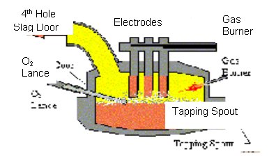
Oxygen may be added to the BCV and SCV by lances to facilitate a carbon-oxygen chemical reaction. The lances may be consumable or water-cooled.
Carbon in the form of coke is added to the furnace in large sacks with scrap charges, or through an injection system. Sacks of 2,500 to 7,500 pounds often are included in the first or second charge to augment the furnace chemical energy. Injection of carbon near the end of the cycle raises the temperature of the bath and reduces iron oxide levels in the slag.
Most furnaces have three openings in the roof for the electrodes, in addition to one for fume evacuation. This additional opening is referred to as the fourth hole. Gases flow out of the fourth hole through a water-cooled elbow, into a water-cooled duct, and on to a gas cleaning system.
The EAF process is energy intensive, with a total energy input of 640 kW-hr/ton. The energy sources are electrical (66 percent), burners (5 percent), and other chemical energy such as carbon combustion and iron oxidation (29 percent). The greatest amount of energy goes into sensible energy of the product steel (57 percent), but the slag holds only 10 percent. The waste terms are important, with 20 percent escaping in the off gas. The remaining portion of the energy goes into cooling water losses and miscellaneous losses (13 percent).
Mathematical Modeling. Our prior work has resulted in the first open literature model of the EAF process based on first principles. The model has four components: (1) a melting model; (2) dynamic material balances; (3) a thermochemical model; and (4) the conservation of energy relation.
Melting Model. The wide variation in the scrap shape and size requires a simplifying assumption to make modeling less complex. The model assumes that the scrap is comprised of n identical spheres of radius R. Although a distribution of radii is easily implemented, lack of detail melting data led us to assume a single sphere R. The partial differential equation describing conduction through a sphere is finite differenced to yield the differential equation:

where:
Ti = temperature at point ri (K)
(K)
 = thermal diffusivity
(cm2/s)
= thermal diffusivity
(cm2/s)
ri
= dimensionless length in radial direction
 r
= dimensionless distance between space points
r
= dimensionless distance between space points
i = 1 center of sphere.
The boundary condition imposed on the system is a symmetry condition at the sphere's center, but the heat flux at the surface is specified by the furnace temperature. Once the surface of the sphere reaches the melting temperature, the sensible energy transferred to the sphere results in decreasing the R of the sphere with the equation.

where:
R = outer sphere R (cm)
T = time (s)
Q = rate of energy transfer to scrap (J/s)
Hmelt = heat
of fusion of steel (J/g)
 solid = density
of solid scrap (g/cm3)
solid = density
of solid scrap (g/cm3)
Nsph = number of spheres of scrap
Material Balances. Material balances track the inflow, outflow, and accumulation of the furnace chemical compounds. The material balances are written around BCV, SCV, and GCV inside the furnace, as shown in Figure 2. We have found that it is much more computationally efficient to develop conservation relations on atomic species, as opposed to chemical species. This is due to the fact that atomic species are conserved so that the resulting differential equations are not nearly as stiff as those based on chemical species. The balance relations are given in Table 1. Three types of rate terms enter the model. They are flows due to: (1) furnace operations; PXY , which are flows of Y atoms into or out of the X control volume; (2) flows due to convection (boiling), FXZY , which are flows of Y atoms from the X control volume into the Z control volume; and (3) flows due to mass transfer, RXZY, which are flows of Y atoms from the X control volume to the Z control volume.

Table 1. Material Balance Ordinary Differential Equations

Thermo-Chemical Model. To predict the chemical compositions of each of the control volumes, assumptions about the rate and type of chemical reactions must be made. The high temperatures present in the EAF ensure that chemical reactions are not kinetically limited. Therefore, it was assumed that equilibrium exists within each control volume, which implies that transport limitations do not exist within a control volume.
Only the compounds of the largest abundance and of the greatest interest to the steel industry were included in the chemistry model and are shown in Figure 3.
With the compounds of interest established and equilibrium assumed, it is possible to calculate the equilibrium composition of all phases in each control volume by minimization of the Gibb's free energy. The RAND algorithm, as described by Smith and Missen (1991), and originally developed by White, et al. (1958), is used. We have assumed that the gas phase and the slag phase in all control volumes is ideal; however, non-ideal conditions are assumed for the liquid phase in the BCV.

Energy Balances. Energy balances are used on each control volume to calculate the temperature of that control volume. This means that the model assumes that all phases in a control volume are at the same temperature. The melting model accounts for the scrap temperature; therefore, the energy balances do not include the scrap.
Model Validation. It is imperative that models of physical processes be tested against real-world data to identify their strengths and weaknesses. The extreme conditions that exist in and around the EAF make collecting a comprehensive set of furnace data difficult. The data most readily available is from "heat sheets," and sometimes dynamic off-gas profiles. To date, we have been able to obtain data from two different furnaces (Plant A and Plant B). Eight of the model parameters were considered poorly understood from first principles, and were determined by curve fitting experimental data to model predictions using a quasi-Newton method available in the Optimization Toolbox of Matlab. The best results for Plant A and Plant B are given in Figures 4 and 5, respectively. Considering the uncertainty in the plant data, the predictive capability of this first principles model is considered good and applicable over a wide range of furnaces.

Figure 5. Plant B Calibration Results

Dynamic Optimization. Once an appropriate mathematical model is developed, it is important to learn if improved operational strategies can be developed. The EAF process is dynamic; therefore, dynamic optimization methods must be used to determine best operational policies. Two important considerations must be made when determining optimal strategies: (1) improving performance strategies; and (2) improving pollution prevention strategies. For our initial studies, we have considered the following performance function to be minimized:

The first term of the performance index accounts for the amount of CO released in the off-gas. The amount of CO released indicates the extent of chemical energy utilization and environmental impact. Minimizing CO reduces the environmental impact of an EAF and maximizes the utilization of chemical energy supplied to the system. The second term minimizes the amount of iron oxide present at the end of the operation. By minimizing iron oxide, we maximize the yield of the process. The third term minimizes the cycle time, and the final term is a penalty function that is non-zero when the bath temperature is below the desired tapping temperature.
To minimize the performance index of the equation above, subject to the constraints that the model equations must always be satisfied, we use the method of Iterative Dynamic Programming. This is a direct method that involves an intelligent search over a state subspace using Bellman's Principle of Optimality.
After determining the measure of furnace behavior, the variables to be manipulated must be determined. Our initial study considered four controls: power-on time, carbon addition rate, oxygen lancing rate, and excess burner oxygen rate.
A shorter power-on time requires a higher input of chemical energy because the tapping temperature must always be attained. Power-on time is controlled through the manipulation of the length of each stage in the dynamic programming algorithm. The electrical power profile remains constant, but the length of the cycle is free to increase or decrease.
The carbon addition rate controls the amount of total chemical energy input, as well as yield. High carbon levels promote reducing conditions, which produce CO but prevent the formation of large amounts of iron oxide. Chemical energy can be recovered by converting CO to carbon dioxide in the freeboard.
Oxygen lancing contributes to the furnace chemical energy by consuming carbon in the bath and increasing the bath temperature. Excess burner oxygen helps to prevent chemical energy waste by scavenging combustible gases in the freeboard.
Using theses control variables, the results of Table 2 were obtained. These are impressive results, both in terms of pollution prevention and process yield. Plant A had a 52 percent reduction in the objective function. The optimal control policies obtained are given in Figure 6. The difference between the base case oxygen lancing strategy and the optimal operation is dramatic; a factor of 10 less oxygen is used in the optimal lancing case. The optimal operation adds carbon almost continuously during the heat, in contrast to all at once for the base case. Carbon addition is 3 times less in the optimal strategy. Excess burner oxygen is used throughout the heat to reduce CO levels.
| Plant A | Plant B | ||||
| Base Case | Optimal | Base Case | Optimal | ||
| Controls | Lancing | 113,770 SCF | 14,140 SCF | 150,221 SCF | 117,500 SCF |
| Carbon Injection | 9560 lb. | 3201 lb. | 4149 lb. | 6075 lb. | |
| Excess O2 | 0 SCF | 23,294 SCF | 0 SCF | 55,000 SCF | |
| Performance | CO | 0.788 | 0.005 | 0.271 | 0.021 |
| (-99.4%) | (-92%) | ||||
| FeO | 0.503 | 0.001 | 1.198 | 0.467 | |
| (-99.8%) | (-61%) | ||||
| Time | 1 | 1.097 | 1.6 | 1.595 | |
| (+9.7%) | (-0.3%) | ||||
| Performance Index | 2.29 | 1.103 | 3.069 | 2.083 | |
| (-52%) | (-32%) |

The optimization results for Plant A show that with optimization, the base operation can be improved in chemical energy utilization and yield. The slightly longer process time comes about because the optimal operation acts less aggressively with respect to chemical energy. Weighting the time portion of the performance function more heavily will encourage a shorter process time.
For Plant B, a 32 percent improvement is attainable. Figure 7 gives the optimal
operational strategy for Plant B. Unlike the base operating strategy, lancing
takes place for nearly the entire heat. Carbon addition occurs at the middle
and end of the cycle. The carbon addition at the end of the cycle plays a vital
role in reducing the iron oxide levels. Excess burner oxygen is used throughout
the cycle to varying degrees to eliminate combustibles from the off-gas.
Process optimization has resulted in significant improvements for both plants.

References:
Worrell E, Martin N, et al. Energy efficiency opportunities in electric arc
steelmaking. In: 56th Electric Furnace Conference Proceedings of the Iron and
Steel Society, pp. 613-622.
McIntyre EH, et al. The challenge of improving electric arc efficiency. Iron and Steel Engineer 1994;71(5):28-33.
Elliott JF. The Physical Chemistry of Steelmaking. Massachusetts Institute of Technology Press, Cambridge, MA, 1956.
Smith WR, Missen RW. Chemical reaction equilibrium analysis: theory and algorithms. Krieger Publishing Co., Malabar, FL, 1991.
Grace A. Optimization Toolbox. The Mathworks, 1993.
Matson SA. Dynamic modeling and optimization of an electric arc furnace. Ph.D. Dissertation. University of Colorado, Boulder, CO, 2000.
Luus R. Optimal control by dynamic programming using accessible grid points and region contraction. Hungarian Journal of Industrial Control 1989;17:523-543.
Luus R. Optimal control by dynamic programming using systematic reduction in grid size. International Journal of Control 1990;51:995-1013
Bojkov B, Luus R. Optimal control of nonlinear systems with unspecified final times. Chemical Engineering Science 1996;51(6):905-919.
Bellman R. Applied Dynamic Programming. Princeton University Press, Princeton, NJ, 1962.
Journal Articles:No journal articles submitted with this report: View all 3 publications for this project
Supplemental Keywords:electric arc furnace, dynamic optimization, mathematical modeling, sustainable industry business economics, business, environmental chemistry, environment engineering, manufacturing NAIC 31-33, sustainable environment, technology, Common Sense Initiative, air pollution control, carbon injection, emission controls, energy efficiency, energy technology, engineering, industrial innovations, innovative technology, material balance models, pollution prevention, waste minimization, waste monitoring, industry sectors, cleaner production, green design, steel production. , Industry Sectors, Sustainable Industry/Business, Scientific Discipline, RFA, Technology for Sustainable Environment, Sustainable Environment, Manufacturing - NAIC 31-33, Environmental Engineering, Environmental Chemistry, Ecology and Ecosystems, Economics and Business, cleaner production, waste reduction, green design, electric arc furnaces, steel production, Common Sense Initiative, engineering, waste minimization, industrial innovations, carbon injection, waste monitoring, air pollution control, energy efficiency, innovative technology, material balance models, emission controls, pollution prevention
Progress and Final Reports:
2000 Progress Report
Original Abstract