|
Klamath Project - Main Page
Facilities in Operation
|
Storage Dams |
3 |
|
Diversion Dams |
4 |
|
Canals |
185 mi |
|
Laterals |
532 mi |
|
Pumping Plants |
28 |
|
Drains |
728.2 mi |
|
Tunnels |
1.9 mi |
|
Storage Facilities
Clear Lake Dam
Gerber Dam
Link River Dam
Diversion Facilities
Lost River Diversion Dam
|
Type: |
Concrete multiple-arch weir, embankment wings |
|
Location |
On the Lost River about 4 miles below Olen, Oregon. |
|
Year Completed |
1912 |
|
Dimensions: |
|
|
Structural height |
42 ft |
|
Hydraulic height |
31 ft |
|
Crest length |
675 ft |
|
Crest elevation |
4,097.0 ft |
|
Volume |
20,000 yd3 |
|
Diversion capacity |
3,000 cfs |
|
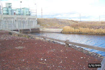
Anderson-Rose Diversion Dam
| |
Reinforced concrete slab and buttress |
| |
On the Lost River about 3 miles southeast of Merrill, Oregon. |
| |
1921 |
|
Dimensions: |
|
|
Structural height |
23 ft |
|
Hydraulic height |
12 ft |
|
Crest length |
324 ft |
|
Crest elevation |
4,064.0 ft |
|
Volume |
1,000 yd3 |
|
Diversion capacity |
800 cfs |
|
Malone Diversion Dam
|
Type: |
Concrete gate structure, embankment wing |
|
Location |
On the Lost River about 11 miles downstream from Clear Lake Dam. |
|
Year Completed |
1923 |
|
Dimensions: |
|
|
Structural height |
32 ft |
|
Hydraulic height |
18 ft |
|
Crest length |
515 ft |
|
Crest elevation |
4,160.3 ft |
|
Volume |
25,000 yd3 |
|
Diversion capacity |
220 cfs |
|
Miller Diversion Dam
|
Type: |
Concrete weir, removable crest, embankment wing |
|
Location |
On Miller Creek 8 miles below Gerber Dam. |
|
Year Completed |
1924 |
|
Dimensions: |
|
|
Structural height |
10 ft |
|
Hydraulic height |
5 ft |
|
Crest length |
290 ft |
|
Crest elevation |
4,227.0 ft |
|
Volume |
2,000 yd3 |
|
Diversion capacity |
190 cfs |
|
Carriage Facilities
"A" Canal
| |
From Upper Klamath Lake near Klamath Falls, Oregon, southeast about 8 miles. |
| |
1906-1907 |
|
Length |
8.7 mi |
|
Diversion capacity |
1,150 cfs |
|
Typical section - initial reach |
|
|
Bottom width |
44 ft |
|
Side slopes |
0.5 1 |
|
Water depth |
11 ft |
|
"B" Canal
|
Location |
From end of "A" Canal east to vicinity of Olene, Oregon. |
|
Construction period |
1906-1912 |
|
Length |
4.1 mi |
|
Diversion capacity |
290 cfs |
|
Typical section - initial reach |
|
|
Bottom width |
16 ft |
|
Side slopes |
0.5:1 |
|
Water depth |
6 ft |
|
"C" Canal
|
Location |
From Main Canal generally southeast to vicinity of Merrill, Oregon. |
|
Construction period |
1907-1908; upper end above "C-G" Canal enlarged in 1921. |
|
Length |
13.5 mi |
|
Diversion capacity |
330 cfs |
|
Typical section - initial reach |
|
|
Bottom width |
32 ft |
|
Side slopes |
2:1 |
|
Water depth |
9 ft |
|
"C-G" Canal
|
Location |
From "C" Canal to "G" Canal near Lost River. |
|
Construction period |
1921 |
|
Length |
0.9 mi |
|
Diversion capacity |
400 cfs |
|
Typical section - initial reach |
|
|
Bottom width |
25 ft |
|
Side slopes |
2:1 |
|
Water depth |
Varies |
|
"D" Canal
|
Location |
From the vicinity of Merril, Oregon, southeast about 15 miles. |
|
Construction period |
1913-1914 |
|
Length |
18.6 mi |
|
Diversion capacity |
300 cfs |
|
Typical section - initial reach |
|
|
Bottom width |
22 ft |
|
Side slopes |
2:1 |
|
Water depth |
5.3 ft |
|
"E" Canal
|
Location |
From vicinity of Olene, Oregon, east along north side of Lost River. |
|
Construction period |
1912 |
|
Length |
10.5 mi |
|
Diversion capacity |
35 cfs |
|
Typical section - initial reach |
|
|
Bottom width |
6 ft |
|
Side slopes |
1.5:1 |
|
Water depth |
5.3 ft |
|
"F" Canal
|
Location |
From vicinity of Olene, Oregon, east along north side of Lost River. |
|
Construction period |
1912 |
|
Length |
11.6 mi |
|
Diversion capacity |
90 cfs |
|
Typical section - initial reach |
|
|
Bottom width |
10 ft |
|
Side slopes |
1.5:1 |
|
Water depth |
4.7 ft |
|
"G" Canal
|
Location |
From the vicinity of Lost River Diversion Works southeast along the Lost River to the vicinity of Merrill, Oregon. |
|
Construction period |
1913-1915 |
|
Length |
8.5 mi |
|
Diversion capacity |
400 cfs |
|
Typical section - initial reach |
|
|
Bottom width |
22 ft |
|
Side slopes |
2:1 |
|
Water depth |
6.5 ft |
|
"J" Canal
|
Location |
From Anderson-Rose Diversion Dam generally southeast to vicinity of Newell, California |
|
Construction period |
1921; enlarged in 1935-1937 |
|
Length |
23.4 mi |
|
Diversion capacity |
800 cfs |
|
Typical section - initial reach |
|
|
Bottom width |
26 ft |
|
Side slopes |
1.5:1 |
|
Water depth |
9.5 ft |
|
"M" Canal
|
Location |
Vicinity of Newell, California. |
|
Construction period |
1947-1948 |
|
Length |
6.5 mi |
|
Diversion capacity |
100 cfs |
|
Typical section - initial reach |
|
|
Bottom width |
4 ft |
|
Side slopes |
1.5:1 |
|
Water depth |
4.2 ft |
|
"N" Canal
|
Location |
East side of Tule Lake Restricted Sump. |
|
Construction period |
1935-1966 |
|
Length |
26.5 mi |
|
Diversion capacity |
300 cfs |
|
Typical section - initial reach |
|
|
Bottom width |
30 ft |
|
Side slopes |
2:1 |
|
Water depth |
Varies |
|
"P" Canal
|
Location |
East side of Lower Klamath Lake. |
|
Construction period |
1941-1942 |
|
Length |
1.8 mi |
|
Diversion capacity |
200 cfs |
|
Typical section - initial reach |
|
|
Bottom width |
16 ft |
|
Side slopes |
1.5:1 |
|
Water depth |
6.3 ft |
|
"P-1" Canal
|
Location |
East Side of Lower Klamath Lake. |
|
Construction period |
1941-1942 |
|
Length |
9 mi |
|
Diversion capacity |
250 cfs |
|
Typical section - initial reach |
|
|
Bottom width |
16 ft |
|
Side slopes |
1.5:1 |
|
Water depth |
6.3 ft |
|
"Q" Canal
|
Location |
From Tule Lake Restricted Sump generally southward. |
|
Construction period |
1960 |
|
Length |
3.9 mi |
|
Diversion capacity |
130 cfs |
|
Typical section - initial reach |
|
|
Bottom width |
10 ft |
|
Side slopes |
2:1 |
|
Water depth |
5.1 ft |
|
"R" Canal
|
Location |
From Tule Lake Restricted Sump generally northwest. |
|
Construction period |
1960 |
|
Length |
3.2 mi |
|
Diversion capacity |
76 cfs |
|
Typical section - initial reach |
|
|
Bottom width |
8 ft |
|
Side slopes |
2:1 |
|
Water depth |
4.2 ft |
|
Lost River Diversion Channel
|
Location |
From the Lost River at a point about 7 miles southeast of Klamath Falls, generally northwest to the Klamath River. |
|
Construction period |
1911-1912; enlarged in 1930 and in 1950 |
|
Length |
7.8 mi |
|
Diversion capacity |
3,000 cfs |
|
Typical section - initial reach |
|
|
Bottom width |
60 ft |
|
Side slopes |
2:1 |
|
Water depth |
Varies |
|
North Canal
|
Location |
From Miller Diversion Dam west to Dry Lake. |
|
Construction period |
1924-1925 |
|
Length |
14.4 mi |
|
Diversion capacity |
190 cfs |
|
West Canal
|
Location |
From Malone Diversion Dam west to Dry Lake |
|
Construction period |
1924-1925 |
|
Length |
12.1 mi |
|
Diversion capacity |
190 cfs |
|
"A" Canal Tunnel
|
Location |
|
|
Construction period |
1907 |
|
Length |
3,300 ft |
|
Capacity |
1,150 cfs |
|
Diameter |
11-13.5 ft |
|
Tule Lake Tunnel
|
Location |
Tule Lake Tunnel, Pumping Plant "D" Discharge Conduit |
|
Construction period |
1940-1941 |
|
Length |
6,600 ft |
|
Capacity |
250 cfs |
|
Cross section |
Horseshoe |
|
Diameter |
5.75 ft |
|
Lining: |
Concrete |
|
Thickness |
3-7 in |
|
Pumping Plants
Pumping Plant F
|
Designation |
Number of units |
Total capacity, cfs |
Total dynamic head, ft |
Total horsepower |
|
Pumping Plants |
|
|
|
|
|
Adams |
|
|
|
|
|
Low Lift |
2 |
35 |
26 |
150 |
|
High Lift |
2 |
25 |
32 |
150 |
|
Main |
7 |
75 |
327 |
3,400 |
|
Booster |
7 |
60 |
125 |
1,120 |
|
Dry Lake |
1 |
50 |
25.5 |
175 |
|
Dry Lake No. 2 |
1 |
15 |
48 |
100 |
|
Plant "A" |
3 |
100 |
20 |
300 |
|
Plant "B" |
3 |
75 |
10.5 |
120 |
|
Plant "C" |
3 |
100 |
12 |
225 |
|
Plant "D" |
5 |
334 |
78 |
3,750 |
|
Plant "E" |
3 |
300 |
10.5 |
500 |
|
Plant "F" |
3 |
300 |
10.5 |
500 |
|
Plant "G" |
3 |
45 |
8 |
60 |
|
Plant "H" |
2 |
30 |
8 |
40 |
|
Plant "J" |
2 |
20 |
16 |
50 |
|
Plant "K" |
1 |
7 |
12 |
15 |
|
Plant "L" |
1 |
10 |
9 |
15 |
|
Plant "M" |
2 |
16.6 |
11 |
35 |
|
Plant "U" |
1 |
10 |
10.5 |
20 |
|
Plant "V" |
2 |
20 |
10.5 |
40 |
|
Plant "W" |
3 |
66 |
8 |
120 |
|
Plant "X" |
1 |
11 |
8 |
20 |
|
Plant "Y" |
2 |
22 |
10.7 |
60 |
|
Plant No. 1 |
2 |
50 |
12 |
120 |
|
Plant No. 2 |
1 |
12 |
12 |
20 |
|
Plant No. 3 |
2 |
50 |
10 |
120 |
|
Plant No. 5 |
2 |
50 |
10 |
120 |
|
Plant No. 6 |
1 |
25 |
10.5 |
60 |
|
Plant No. 10 |
2 |
24 |
13 |
45 |
|
|

