| Two water distribution system simulators (DSS) are in operation at EPA’s Test and Evaluation (T&E) Facility in Cincinnati, Ohio. The facility is a multifaceted research center where water treatment and other environmental protection technologies are conceived, designed, and evaluated in the laboratory, and at the bench and pilot plant scales. EPA designed and fabricated the two systems to evaluate and understand the dynamics that influence water quality within water distribution infrastructures in the United States and abroad.
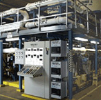
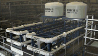
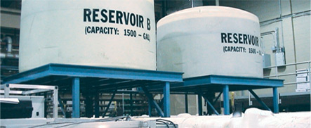
The first distribution system simulator (DSS-1) replicates continuous flow conditions. Six 75-foot (25-meter) lengths of 6-inch (15-centimeter) diameter ductile iron pipe are arranged into “pipe loop” configurations to simulate a distribution system. This pipe loop system can be configured to operate as independent individual loops, collectively as one unit, or in various configurations according to EPA’s experimental research needs. DSS-1 is equipped with two 1,500-gallon reservoir tanks to simulate a comprehensive distribution infrastructure system. This unique engineering design permits operating any combination and configuration of the six loops under various experimental operating parameters. (See Table 1) Each loop is insulated and fitted with a heat exchanger to maintain constant temperature conditions during operation. The distribution system simulator is interfaced with a Supervisory Control and Data Acquisition (SCADA) system, which is used to continuously monitor, control, and archive operating conditions and collected data.
Biofilm samples are collected on “coupons.” Coupons are metal devices that enable scientists to collect samples from the interior surface of a pipe without disrupting water flow. You might say coupons are harvesting mechanisms. They are removed from the distribution pipe, the biofilm sample is scraped off the coupon, and then the coupons are repositioned into the distribution pipe.
The second distribution system (DSS-2) is more than 300 feet long and is a once-through system composed of 6-inch (15-centimeter) diameter PVC pipe. DSS-2 is being used to evaluate water quality in a dead-end branch of a distribution system and to develop design models for water distribution.
Both DSS units are located above ground to allow easy access to the entire pipe network. Ongoing experimental studies (see Table 2) help scientists understand the physical, chemical, and biological activities that occur within drinking water distribution systems.
Research Goals
The distribution system simulators provide researchers with a way to study how water quality is affected during distribution. The research results will be used to provide guidance on how to maintain a high level of water quality.
The goals of DSS research are to: |
- Fabricate above-ground water distribution system simulators that allow easy access and can be operated under controlled conditions
- Conduct studies to develop a better understanding of the dynamics that occur in drinking water distribution systems
- Determine what physical, chemical, and biological factors influence biofilm growth within drinking water distribution systems
- Develop and test mechanisms for the control of biofilm growth within a simulated distribution system
- Develop, evaluate, and demonstrate real-time monitoring, data collection, and archiving of water quality parameters within water distribution systems, using remote telemetry. These research results will be used to provide guidance on how to use remote monitoring of water quality to detect changes in water quality within distribution systems.
Table 1. Operating Parameters of the Distribution System Simulator
| Parameter |
Normal Operation |
Experimental Test Conditions |
| Distribution System Simulator |
Parallel (six individual distribution system simulators) |
Parallel or series in groups of 6, 3, 2, or 1 |
| Housing |
Ductile iron (non-lined) |
Ductile iron (non-lined) |
| Flow |
88 gpma or 1 ft/secb |
No flow to 140 gpm or 0 to 1.6 ft/sec |
| Temperature |
60 oF (15.5 oC) |
35 oF (1.6 oC) to ambient temperature |
| Chemical Control |
Free chlorine 1.0 ppmc |
Chemical control as needed |
| pH |
7.0 to 7.5 |
Control/monitor as needed |
| Turbidity |
<0.5 NTUd |
Control/monitor as needed |
| Water Supply |
Cincinnati tap water (chlorinated) |
Dechlorinated, deionized, tanked, surface water (e.g., river water) |
agallons per minute
bfeet per second
cparts per million
dnephelometric turbidity units
Table 2. DSS Studies
| No. |
Study Title |
| 1 |
Preliminary Studies of Biofilm Formation in Pilot-Scale Distribution Systems |
| 2 |
Opportunistic Pathogens in Biofilms |
| 3 |
Effects of a Pollution Event on a Simulated Water Distribution System |
| 4 |
Impact of Nutrient Removal on Growth Potential for Bacteria |
| 5 |
Impact of Alternative Treatment on Biofilm Growth |
| 6 |
Real-Time Monitoring and Control of Distribution Systems |
| 7 |
Effects of pH Changes on Biofilm Growth in a Distribution System |
| 8 |
Bacterial Growth in Distribution Systems |
Technical Contact:
Jeff Yang (513) 569-7655
See Also:
Distribution Systems Research
Corrosion, Scaling, and Metal Mobility Research
Test and Evaluation Facility
Characterizing the Effect of Chlorine and Chloramines on the Formation of Biofilm in a Simulated Drinking Water Distribution System (PDF) (46 pp, 501 KB) |