|
Copyright © 2008, Eli Lilly and Company and the National Institutes of Health Chemical Genomics Center. All Rights Reserved. For more information, please review the Privacy Policy and Site Usage and Agreement.
- STEPS TO ASSAY DEVELOPMENT FOR SPA FORMAT
- STEPS TO ASSAY DEVELOPMENT FOR FILTER FORMAT
- INTRODUCTION
- REAGENTS
- SCINTILLATION PROXIMITY ASSAYS (SPA)
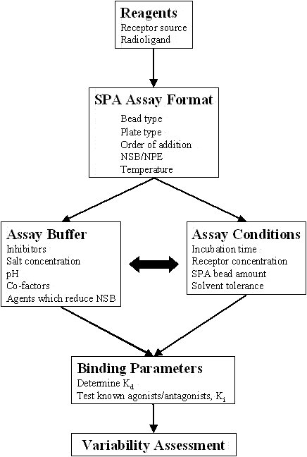
- SPA ASSAY FORMAT
- ASSAY BUFFER
- ASSAY CONDITIONS
- BINDING PARAMETERS
- FILTRATION ASSAYS
- FILTER ASSAY FORMAT
- ASSAY BUFFER
- ASSAY CONDITIONS
- BINDING PARAMETERS
- SPECIAL CIRCUMSTANCES
- PRACTICAL USE OF FLUORESCENCE POLARIZATION IN COMPETITIVE RECEPTOR BINDING ASSAYS
- ABBREVIATIONS
- ADDITIONAL RESOURCES

There are two typical assay formats used for analysis of receptor-ligand interactions in screening applications, filtration and scintillation proximity assay (SPA). Both formats utilize a radiolabeled ligand and a source of receptor (membranes, soluble/purified). Receptor binding assays using non-radioactive formats (fluorescence polarization, time-resolved fluorescence, etc.) which are continually being investigated for feasibility, would have similar assay development schemes to those presented in this document.
Selection of the detection method to be used (SPA, filtration, non-radioactive) is the first step to receptor binding assay development. In some cases, investigation into more than one format may be required to meet the following desired receptor binding criteria:
- Low nonspecific binding (NSB)
- > 80% specific binding at the Kd concentration of radioligand
- Less than 10% of the added radioligand should be bound (Zone A)
- Steady state obtained and stability of signal maintained
- For competition assays, the radioligand concentration should be at or below the Kd
- No dose response in the absence of added receptor
- Reproducible
- Appropriate signal window (i.e. Z-factor > 0.4, SD window > 2 SD units)
While developing receptor binding assays, some of the experiments may need to be performed in an iterative manner to achieve full optimization. In addition preliminary experiments may be required to assess the system.
In many instances, a multi-variable experimental design can be set up to investigate the impact of several parameters simultaneously, or to determine the optimum level of a factor. It is strongly recommended that full assay optimization be performed in collaboration with an individual trained in experimental design.
Experimental design and assay variability is addressed in detail in other sections of this handbook.
The following pages should be used as a general developmental guide to receptor binding assays using SPA or filtration formats.
Quality reagents are one of the most important factors involved in assay development. Validated reagents of sufficient quantity are critical for successful screen efforts over a long period of time. The primary reagents required for a radioactive receptor binding assay which are discussed on the following pages are:
- Receptor (membranes or purified)
- Radioligand
A section on methods of generating reagents for membrane binding assays can be found in the Appendix for the Receptor Binding Assays section of this handbook.
SPA assays do not require a separation of free and bound radioligand and therefore are amenable to screening applications. A diagram for a standard receptor binding SPA is shown below for a 125I radioligand.

General Steps for an SPA assay:
- Add and incubate test compound, radioligand, receptor and SPA beads in a plate (in some cases, the SPA beads are added at a later time point).
- Count plates in microplate scintillation counter. The appropriate settling time needs to be determined experimentally.
|
Advantages
|
|
Disadvantages
|
Non-separation method
No scintillation cocktail required
Reduced liquid radioactive waste
Reduced handling steps (add, incubate, read)
Multiple bead types (WGA, PEI-coated, etc.)
|
More expensive - requires license
Lower counting efficiency
Primarily for 3H and 125I (33P, 35S possible)
Non-proximity effects
Quenching by colored compounds
Difficult to perform kinetic experiments
Bead settling effects
|
Many of the advantages and disadvantages are addressed in the following sections.
The SPA bead surface-coupling molecule selected for use in a receptor binding assay must be able to capture the receptor of interest with minimal interaction to the radioligand itself. The table below lists the available SPA bead capture mechanisms that can be used with various receptor sources.
|
Receptor
|
SPA Bead
|
Capture Mechanism
|
|
Membranes
|
WGA [1]
|
Glycosylation sites
|
|
|
Poly-L-lysine
|
Negative charges
|
|
|
|
Soluble/Purified
|
WGA
|
Glycosylation sites
|
|
|
Streptavidin
|
Biotinylated site
|
|
|
Antibody [2]
|
Specific antibody
|
|
|
Copper
|
His-Tag
|
|
|
Glutathione
|
GST-fusion
|
[1] Wheat germ agglutinin (WGA) SPA beads are available in standard untreated format and two different versions that have been treated with polyethyleneimine (PEI).
In addition to the SPA bead types listed above, FlashBlue GPCR beads are available from Perkin Elmer Life and Analytical Sciences.
[2]Secondary antibody SPA beads are available to capture specific antibodies from the following species: Rabbit, Sheep/Goat, Guinea pig, mouse. Protein A SPA beads are also available for antibody capture.
In addition to the capture mechanism, two types of SPA beads are available:
- Plastic SPA beads, made of polyvinyltoluene (PVT), act as a solid solvent for diphenylanthracine (DPA) scintillant incorporated into the bead
- A Glass SPA bead, or Yttrium silicate (YSi), uses cerium ions within a crystal lattice for the scintillation process. In general, YSi is a more efficient scintillator than PVT is, but YSi SPA beads are requires continuous mixing even during dispensing.
Typical experiments to investigate nonspecific binding of radioligand to SPA beads include varying the amount of radioligand (above and below the predicated Kd value) and the amount of SPA beads (0.1 mg to 1 mg) in the absence of added membrane protein. Results from this experiment can identify the proper type of SPA beads to use in future experiments, as well as the baseline background due to non-proximity effects. An example experiment using a kit from GE Healthcare (formerly Amersham Biosciences) that contains several different SPA bead types (Select-a-Bead kit, #RPNQ0250) is shown below.

For this example, which was performed in the absence of added membrane receptor, the PVT-PEI WGA Type A SPA beads yields the lowest interaction with the radioligand and was used for further assay development. An increase in signal with an increasing amount of added SPA beads is normal. Additives may be useful in decreasing high levels of nonspecific binding of radioligand to the SPA beads (see table of Agents which Reduce NSB in the Assay Buffer section).
The type of plate that is used for SPA receptor binding assays may be influenced by the following factors:
- Counting instrument used (Trilux, TopCount, CLIPR, LeadSeeker)
- Miniaturization (96-well, 384-well)
- Binding of radioligand to plastics
- Liquid dispensing/automation equipment
The table below lists typical choices for SPA assays:
|
Plate Type
|
Instrument
|
# of Wells
|
Comments
|
|
Costar #3632
|
Trilux
|
96
|
White/Clear-bottom, 96-well
|
|
Costar #3604
|
Trilux
|
96
|
White/Clear-bottom, 96-well, non-binding surface (NBS), may be useful when ligands are sticky
|
|
PE LAS 401
|
Trilux
|
96
|
Clear/flexible, not amenable to automation or liquid dispensing instrumentation
|
|
Costar #3706
|
Trilux
|
384
|
White/Clear-bottom, 384-well
|
|
PE LAS Optiplate
|
TopCount
|
96
|
White/solid bottom, 96-well
|
The data shown below demonstrates an advantage of the NBS plates when using a radioligand, which binds nonspecifically to plate plastic.
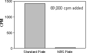
69,000 CPM of 125I-labeled ligand added to the well, incubated for 60 min. Radioactivity removed and wells washed. SPA beads then added. Data demonstrates that a radioligand sticking to the plate surface can elicit an SPA signal. NBS plate yields significantly less nonspecific binding of radioligand.
The order of addition for reagents may affect assay performance as well as ease of automation. Three basic formats have been used:
|
Method
|
|
Advantage
|
Membrane precoupled to SPA bead
Time zero (T=0) addition of SPA beads
Delayed addition of SPA beads
|
May aid in lowering NSB
Easily automated
Optimum ligand/receptor interaction possible
|
Time zero or delayed additions are the most commonly used formats in HTS, with time zero addition requiring fewer manipulation steps. Experiments may be required to determine the optimum method to be used for a particular receptor to maximize signal to background levels.
In addition, the effect of DMSO on intermediate reactants should be investigated. If compounds in DMSO are added into the wells first (most common method for screening efforts), other reagents added (i.e. radioligand, membranes, beads, etc.) may be affected by the concentration of DMSO, or if the time before reaching the final reaction mixture becomes significant.
In order to obtain the maximum signal to noise ratio possible for SPA receptor binding assays, it is important to understand the two different types of signals associated with the radioligand and SPA beads, which may contribute to the total assay background levels.
This signal is attributed to radiolabel which may adhere to the SPA beads themselves and not through a specific interaction with the receptor attached to the SPA bead (Left panel, below). This component of background signal can be determined in the presence of an excess concentration of competitor in the absence of the membrane receptor. Reduction of this factor can be accomplished through the careful use of buffering systems and the appropriate bead type. Determination of NSB to the SPA beads is separate from the NSB associated with membrane receptor preparations.
A competition experiment using an unlabeled compound in the absence or presence of added receptor may assist in identifying nonspecific binding problems.
NPE occurs when either the concentration of the radioligand or the concentration of SPA beads is sufficiently high enough to elicit a signal from the emitted β-particles. This can occur even though the labeled ligand is not attached directly to the SPA bead through the interaction with the receptor or the nonspecific interaction with the bead (Right panel, below). In general, this signal is a linear function, directly proportional to the concentrations of each of these reagents. Therefore, a careful balance between radiolabel and SPA beads is crucial to maximize signal and sensitivity while minimizing NPE and ultimately cost. The only technique available to minimize NPE is adjustment of the SPA bead or radiolabel concentrations.

For routine SPA binding assays, nonspecific binding may be a combination of nonspecific binding to SPA beads as well as nonspecific binding to the receptor, and are expressed as one. Total nonspecific binding is measured in the presence of an excess concentration of unlabeled competitor.
Typically, receptor binding assays used in screening efforts are performed at room temperature. Comparison experiments may be required if other temperatures are considered. A kinetic analysis may be necessary as well. The data below depicts an SPA receptor binding assay performed at three temperatures.

Note: Since in nearly all cases, the microplate scintillation counter is at room temperature, and a 96-well plate requires approximately 16 minutes to read, it is difficult to perform SPA assays at temperatures other than room temperature. Data shown at the left was generated by incubation of a limited number of wells (n=4, different plates) at the indicated temperatures and counting them rapidly in the instrument. The information is useful in areas where there are significant variations in day-to-day laboratory temperatures.
Identify appropriate starting buffer from literature sources or based on experience with similar receptors. Binding assays may require CaCl2, MgCl2, NaCl or other agents added to fully activate the receptor. pH is generally between 7.0 to 7.5. Commonly used buffers include TRIS or HEPES at 25 mM to 100 mM. Protease inhibitors may be required to prevent membrane degradation.
The following are possible factors that can be investigated in a statistically designed experiment to improve radioligand binding to membrane receptors, or reduce radioligand binding to SPA beads. The optimization of the assay buffer may be an iterative process in conjunction with the optimization of the assay conditions to achieve acceptable assay performance. Typical concentrations or concentration ranges for some reagents are listed in the tables below. Other reagents may be required depending on the individual receptor/ligand system.
Note that for most instances, the highest purity reagents should be tested. In some cases, such as with BSA, several forms (fatty acid free, fatty acid containing) may need to be investigated.
|
Agents which Reduce NSB
|
|
BSA
|
0.05% - 0.3%
|
|
Ovalbumin
|
0.05% - 0.3%
|
|
NP-40
|
0.05% - 0.3%
|
|
Triton X-100
|
0.05% - 0.1%
|
|
Gelatin
|
0.05% - 0.3%
|
|
Polyethylenimine
|
0.01% - 0.1%
|
|
CHAPS
|
0.5%
|
|
Tween-20
|
0.05% - 0.1%
|
|
Fetal bovine serum (FBS)
|
up to 10%
|
|
Antioxidants/Reducing Agents
|
|
Ascorbic Acid
|
0.1%
|
|
Pargyline
|
10 μM
|
|
DTT
|
1 mM
|
|
Reduce SPA Bead Settling Effects
|
|
Glycerol
|
10 - 20%
|
|
Glucose
|
10 mM
|
|
Polyethylene glycol (PEG)
|
5 - 10%
|
|
Divalent Cations
|
|
Magnesium (Mg2+)
|
1 mM - 10 mM
|
|
Sodium Acetate
|
10 mM - 50 mM
|
|
Calcium (Ca2+)
|
1 mM - 10 mM
|
|
Zinc (Zn2+)
|
10 μM - 50 μM
|
|
Other Buffer Additives
|
|
NaCl
|
100 mM - 150 mM
|
|
KCl
|
5 mM - 80 mM
|
|
TRIS
|
10 mM - 50 mM
|
|
HEPES
|
5 mM - 100 mM
|
|
Phosphate Buffer
|
20 mM
|
|
pH
|
7.0 - 8.0
|
|
Aprotinin
|
500 units/ml
|
|
EDTA
|
0.51 mM - 5 mM
|
In addition to Aprotinin and EDTA, other protease inhibitors may be required for receptor stability. As a starting point, Complete™ tablets from Roche Molecular Biochemicals are commonly used.
Setup: Measure total binding (receptor + radioligand + SPA beads) and nonspecific binding (receptor + radioligand + excess unlabeled competitor + SPA beads) at various times using repetitive counting on the microplate scintillation counter.
Results Analysis: Plot total, NSB and specific binding (total binding - NSB) versus time
Since steady state will require a longer time to reach at lower concentrations of radioligand, these experiments are usually performed at radioligand concentrations below the Kd (i.e. 1/10 Kd) if signal strength permits. In addition, the total concentration of radioligand bound should be equal to less than 10% of the concentration added to avoid ligand depletion. The receptor concentration added must be lowered if this condition is not met.
This experiment is used to determine when a stable signal is achieved and how long a stable signal can be maintained. The signal is a combination of receptor/ligand reaching steady state and bead settling conditions. As SPA beads become packed at the bottom of the well, the efficiency of counting (particularly with 125I) increases. Therefore, it is important to determine when a uniform signal is obtained and adopt this time window as standard practice. In many assays. 8-16 hours are required for stable signal counting. Use approximately 0.125-0.5 mg SPA beads depending on results from preliminary experiments.
An example of an incubation time course is shown below. A minimum of 10 hours incubation time was chosen in this example and the interaction was stable for at least 24 hours. Failure to operate a receptor/ligand binding assay at steady state conditions may result in erroneous calculations for binding constants (Kd or Ki).

Setup: Measure total binding (receptor + radioligand + SPA beads) and nonspecific binding (receptor + radioligand + excess unlabeled competitor + SPA beads) at various levels of added receptor (typical μg amounts vary depending on the source and purity of receptor).
Results Analysis: Plot total, NSB and specific binding (total - NSB) versus receptor amount. Plot total bound/total added expressed as a percent versus receptor concentration. Determine the level of receptor that yields <10% total binding/total added (Zone A).
It is ideal to keep the total amount of radioligand bound at less than 10% of the total amount added to avoid ligand depletion. This is considered the acceptable limit and is referred to as “Zone A”. Saturation experiments must be performed at <10% total ligand binding at all concentrations tested (0.1 x Kd to 10 x Kd), so an initial protein variation experiment at a radioligand concentration that is 0.1 x Kd is typically performed.
The example shown below uses radioligand at < 0.1 Kd and an increasing amount of membrane receptor protein. Two plots are shown: (Left) raw SPA data for total, NSB and specific; (Right) total bound/total added expressed as a percent. In this example, receptor levels less than 1.7 μg/well would meet Zone A requirements.

Total counts added (using liquid scintillation counting) are determined differently than the bound counts (SPA), therefore, in order to plot the % Total Bound/Added, the efficiency for each method must be taken into account, and any CPM data converted to DPM (described in APPENDIX). You cannot compare the CPM data from one instrument/scintillation method to that of another. The Section entitled “DPM Mode for SPA” demonstrates a representative method for determining efficiency for SPA bead counting. DPM for liquid scintillation counting can be obtained from the instrument directly. The stable signal count time must be determined prior to these experiments. If the signal dips after a high concentration of receptor, then the SPA beads may be in limited amounts.
Setup: Measure total binding (receptor + radioligand + SPA beads) nonspecific binding (receptor + radioligand + excess unlabeled competitor + SPA beads) and non-proximity effects (radioligand + SPA beads) at various SPA bead levels (typically 0.125 mg to 1.5 mg) using the determined optimum incubation time and optimum receptor concentration.
Results Analysis: Plot total, NSB, NPE, and specific binding (total - NSB) versus SPA bead amount. Choose a bead concentration beyond the linear range, at or near the initial saturation level on the specific binding curve.

Non-proximity effects (NPE) can be determined in the absence of added receptor. Ideally, the NPE signal would be identical to the nonspecific signal in the presence of unlabeled competitor. A level of SPA beads at 0.35 mg - 0.5 mg would provide the best economical signal for this example.
Setup: Measure total binding (receptor + radioligand + SPA beads) and nonspecific binding (receptor + radioligand + excess unlabeled competitor + SPA beads) at various concentrations of DMSO (or other solvent) using the determined optimum incubation time, optimum receptor concentration and optimum SPA bead amount.
Results Analysis: Plot total and NSB versus final assay concentration of DMSO
If the developed SPA receptor binding assay will be used to test organic compounds, interference with DMSO will need to be determined. As shown in the example data below, there can be significant signal reduction if the DMSO concentration becomes too high.

The level of DMSO in a SPA binding assay is determined by data in experiments such as the one in the example above and by the requirement set to maintain compound solubility.
Additional solvents (methanol, ethanol, etc.) or other agents (i.e. β-cyclohexadextrin) may need to be tested if compounds will be received in these other diluents.
Once determined, the solvent should be included in any further assay development or compound testing, including controls.
As an additional verification of minimal solvent interference, test competitive binding with a known competitor in the absence or presence of solvent at the determined level to be used in assays. Ideally, the test compound will have high affinity for the receptor and be freely soluble in aqueous buffer. The IC50 should not change in the absence or presence of the solvent.
The determination of the equilibrium dissociation constant for the radioligand (Kd) or equilibrium dissociation constants for unlabeled compounds (Ki) should be performed after the SPA receptor binding assay has been fully optimized for the conditions outlined in the prior sections.
Three methods are described for the determination of the receptor affinity for the radioligand, Kd:
- Saturation analysis
- Homologous competition
- Association rate at various radioligand concentrations
A heterologous competition binding assay is used to determine the affinity of the receptor for an unlabeled compound, Ki.
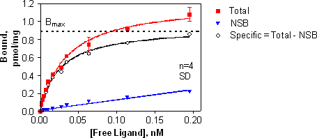
An equilibrium saturation binding experiment measures total and nonspecific binding at various radioligand concentrations. The equilibrium dissociation constant or affinity for the radioligand, Kd, and the maximal number of receptor binding sites, Bmax, can be calculated from specific binding (total - NSB) using non-linear regression analysis.
Requirements:
- Steady state for low concentrations of radioligand (i.e. 1/10 estimated Kd) has been reached - perform association experiment to verify if necessary.
- Ensure that <10% of the added radioligand is bound (at all radioligand concentrations tested) to prevent ligand depletion - if this is not met, lower the receptor concentration
The range of radioligand concentrations tested in a saturation binding experiment is typically from 1/10 Kd to 10x Kd to yield an appropriate curve for nonlinear regression analysis methods. Radioligand specific activity, concentration or expense may prevent a wide range of concentrations from being used.
A high concentration of unlabeled compound (1000 x Ki or Kd value) is used to determine nonspecific binding. Ideally, the unlabeled compound should be structurally different than the radioligand. Nonspecific binding should be less than 50% of the total binding at the highest concentration of [L] tested.
Calculate Kd for specific binding using a one-site binding hyperbola nonlinear regression analysis (i.e. GraphPad Prism) as shown in the equation below:

Bmax is the maximal number of binding sites (pmol/mg), and Kd (nM, pM, etc.) is the concentration of radioligand required to reach half-maximal binding.
Setup: Measure total binding (receptor + radioligand + SPA beads) and nonspecific binding (receptor + radioligand + excess unlabeled competitor + SPA beads) at various concentrations of radioligand using the determined optimum incubation time, optimum receptor concentration and optimum SPA bead amount. Include the expected concentration of DMSO or other solvent for compound testing. To assess non-proximity effects (NPE), a condition without receptor can be included (radioligand + SPA beads).
Results Analysis: Plot total, NSB and specific binding (total - NSB) versus free concentration of radioligand. Plot NPE if no receptor condition was performed.
A representative saturation binding experiment is shown below. Y-axis data has been expressed in pmol/mg, using conversion methods shown in the Appendix.
A listing of the calculations required for analysis of saturation binding data is shown below. Details for each of these calculations are shown in the Appendix.
- Determine total radioactivity added per well by counting an aliquot of each radioligand mix in a gamma counter or a liquid scintillation counter. Convert to DPM if necessary using the equation below:
DPM = CPM/Efficiency
- Convert binding data (total bound, NSB) from CPM to DPM data using above equation.
- Calculate specific binding in DPM: Specific bound = Total Bound - NSB
- Calculate unbound (free) DPM: Free = Total Added - Total Bound
- Convert free DPM to concentration units (i.e. nM) using the radioligand specific activity (expressed as DPM/fmol) and the volume of sample used.
- Convert Total bound, NSB and Specific bound DPM to pmol/mg units using specific activity expressed as DPM/fmol and the amount of receptor added per assay well in mg units.
- Plot Bound (in pmol/mg) on Y-axis versus Free concentration of radioligand (in nM) on X-axis.
- Determine Kd and Bmax using a non-linear regression analysis for a single site binding (hyperbola).
The binding reaction must be at equilibrium for all concentrations of radioligand. Lower concentrations of radioligand require longer times to reach equilibrium.
Less than 10% of the total added radioligand should be bound at all concentrations of radioligand tested. At lower concentrations of radioligand, it is more likely that greater than 10% of the added radioligand will be bound (if this is the case, receptor concentration should be lowered).
If reagents and the assay system allow, radioactive concentrations of at least 10 times the Kd should be tested to provide suitable data for a nonlinear regression analysis and accurate determination of the binding parameters. The Kd and Bmax values can be calculated from less than complete data sets, but the statistical reliability of the returned values may be lower.
Ideally, nonspecific binding should be less than 50% of the total binding.
No positive or negative binding cooperativity
Binding is reversible and obeys the Law of Mass Action:
In the past, nonlinear saturation binding data was transformed into linear data followed by analysis using linear regression, resulting in a Scatchard (or Rosenthal) plot. Although perhaps useful for the display of data, the Scatchard plot is not used anymore for the determination of Kd or Bmax values. These values are determined using nonlinear regression analysis as described above. Scatchard plots distort the experimental error (X value is used to calculate Y), hence the assumptions of linear regression are violated and the resulting values are not accurate.
It is inappropriate to analyze transformed data for the determination of Kd and Bmax.
A homologous competition is a concentration response curve with an unlabeled compound that is identical to the radioligand being used. Radioligand concentration is constant in the experiment. Homologous competition experiments can be used as an alternative to saturation experiments to determine receptor affinity (Kd) and density (Bmax), provided the criteria shown below are met. When using [125I]-ligands, a non-radioactive iodo-ligand should be used if possible.
Assumptions:
- The receptor has identical affinity for the radioligand and unlabeled ligand.
- There is no cooperativity.
- No ligand depletion (<10% of the total added radioligand is bound)
- Nonspecific binding is proportional to the concentration of labeled ligand.
The concentration-response curve should ideally descend from 90% specific binding to 10% specific binding over an 81-fold (or approximately 2 log scales) increase in concentration of the unlabeled ligand.
A homologous competition experiment has been designed correctly if the IC50 is between 2 and 10 times the concentration of radioligand.
Two methods can be used to analyze data from a homologous competition experiment and determine the Kd and Bmax. They are described below as Results Analysis 1 and Results Analysis 2. The experimental setup is identical for both types of analysis.
Setup: Measure binding (receptor + radioligand + SPA beads) at various concentrations of unlabeled competitor using a single concentration of radioligand (≤Kd) and the determined optimum incubation time, optimum receptor concentration and optimum SPA bead amount. In some cases (3H-label with low specific activity), concentrations above the Kd may be required. Total binding is determined in the absence of any added competitor. Nonspecific binding (receptor + radioligand + excess unlabeled competitor + SPA beads) is included for calculation of specific binding.
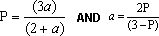
Results Analysis 1: Plot specific bound (Bound - NSB) at each concentration of unlabeled competitor. Conversion to percent specific bound is performed using the following equation:

Step 1. Determine the IC50 using a sigmoidal dose-response (variable slope), which is also known as a four-parameter logistic nonlinear regression analysis (i.e. using GraphPad Prism) as shown in the equation below (use log concentration values for proper analysis):

Representative data for a homologous competition:

Step 2. Determine the Kd and Bmax using nonlinear regression analysis (i.e. GraphPad Prism) for the following equation:

[Hot] is the concentration of radioligand used in the assay (in nM)
[Cold] is the concentration of competitor, which varies, (in nM)
In GraphPad Prism, enter Y in CPM or DPM and X in log concentration of competitor.
Calculate Kd and Bmax with above curve fit analysis. Use instrument counting efficiency and specific activity of radioligand to convert the calculated maximum signal units (CPM or DPM) to pmol/mg units.
The calculated IC50 for this homologous competition experiment is 1.5 x 10⁻¹⁰ M.
The concentration of [L] used in this homologous competition is 3.8 x 10⁻¹¹ M.
The calculated IC50 is between 2 and 10 times the concentration of added [L].
The concentration-response curve descends from 90% specific binding to 10% specific binding over an 86-fold increase in concentration of the unlabeled ligand.
Inputting X (log concentration) and Y (Total DPM) into the homologous binding analysis equation above yields (in parentheses are the values obtained from saturation binding analysis):
Log Kd = -9.962 → Antilog of -9.962 = 1.09 x 10⁻¹⁰ M = 109 pM (79 pM)
Bmax = 27773 DPM → Convert using specific activity, Bmax = 12.5 pmol/mg (5 pmol/mg)
Results Analysis 2:
Alternatively, convert specific DPM bound to molar units (i.e. nM) bound.
- The molar concentration of labeled ligand ([L]) is calculated using the DPM added per well, the specific activity and the conversion factor, 1 μCi = 2.2 x 10⁶ DPM.
The formula is [L] nM = (specific counts) * (1/2200000) * (1 / Specific Activity) * 10000
- This concentration is added to all concentrations of unlabeled ligand to determine the final added ligand concentration.
- As the added ligand concentration increases (due to increase added unlabeled ligand), the specific activity of the labeled ligand is decreased.
- For each specific DPM bound determine the specific molar units bound by using the corresponding specific activity in that condition.
The formula is [RL] = (added ligand) * (specific DPM) / (DPM added per well).
- Use a one-site binding (hyperbola) similar to the saturation binding data to calculate Kd and Bmax.
Example:
Labeled ligand specific activity is 90 Ci/mmol and 66398 dpm are added per well (100 μl final volume). The concentration of labeled ligand in all wells is 3.3 nM. At unlabeled ligand concentration of 125 nM, the final added ligand (unlabeled + labeled) is 128.3 nM.
If the specific binding at 125 nM unlabeled ligand condition is 3283 DPM, then the specific molar unit bound would be (3283 x128.3)/66398 = 6.34 nM.
Representative results for homologous competition analyzed using the Results Analysis 2 method is shown on the following page.
Homologous Competition for Determination of Kd
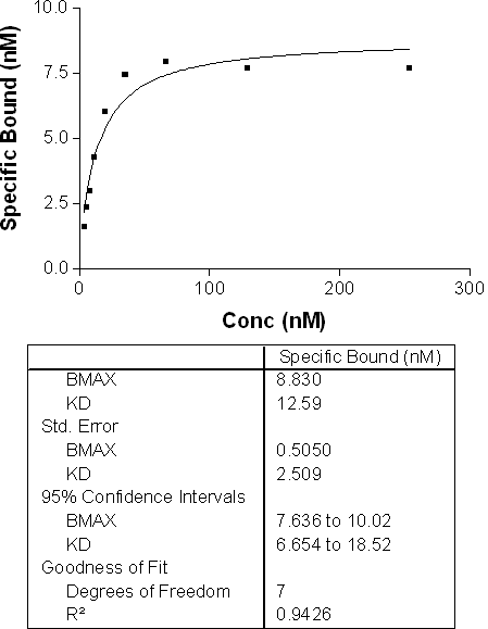
In this example data, the Kd determined from a homologous competition experiment is 12.6 nM.
An optional method, which can be used early in development for both determination of optimum incubation time and provide an estimate for the Kd, is to perform an association rate experiment at various radioligand concentrations.
Setup: Measure total binding (receptor + radioligand + SPA beads) and nonspecific binding (receptor + radioligand + excess unlabeled competitor + SPA beads) at various times and at various concentrations of added radioligand.
Results Analysis: Plot specific binding (total binding - NSB) versus time at each radioligand concentration tested.
Calculate the observed association rate constant (kobs) by fitting the signal versus time data to a one-phase exponential association nonlinear regression analysis for each concentration of radioligand tested. The kobs value is returned as one of the resulting curve fit parameters. There will be different kobs for each radioligand concentration.
Plot the observed association rate constant (kobs) versus concentration of [L].
This should result in a linear function with a slope equal to the association rate constant (kon) and the Y-intercept equal to the dissociation rate constant (koff). An estimate for the equilibrium dissociation constant (Kd) can be calculated using the equation below with the kinetically determined rate constants:
Kd = koff/kon
Example Data:
SPA Method: Reaction mix was read at different time points

The Kd calculated from saturation binding for this receptor was 35 pM.
Experimentally, a heterologous competition is identical to a homologous competition. Heterologous competition assays measure concentration-response binding with unlabeled ligands that are structurally different than the radioligand. The IC50 for the unlabeled compound is determined from the experimental data and the equilibrium dissociation constant, Ki, can be calculated using a mathematical formula (Cheng-Prusoff equation).
Setup: Measure binding (receptor + radioligand + SPA beads) at various concentrations of unlabeled competitor using a single concentration of radioligand (≤Kd) and the determined optimum incubation time, optimum receptor concentration and optimum SPA bead amount. Total binding is determined in the absence of any added competitor. Nonspecific binding (receptor + radioligand + excess unlabeled competitor + SPA beads) is included for calculation of specific binding.
Results Analysis: Plot specific bound (Bound - NSB) at each concentration of unlabeled competitor. Conversion to percent specific bound is performed using the following equation:

Determine IC50 using a sigmoidal dose-response (variable slope), which is also known as a four-parameter logistic nonlinear regression analysis (i.e. using GraphPad Prism) as shown in the equation below:
where Y is the specific binding and X is the log concentration of competitor.
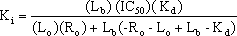
Calculate the equilibrium dissociation constant for the unlabeled compound (Ki) using the Cheng-Prusoff equation (valid when Hill Slope is near unity):
Ki = IC50/[1 + ([L]/Kd)]
where
- Ki is the equilibrium dissociation constant for the unlabeled compound
- IC50 is the concentration causing 50% inhibition of binding
- [L] is the concentration of radioligand
- Kd is the equilibrium dissociation constant for the radioligand
- Further calculation details on the Cheng-Prusoff equation can be found in the Appendix.
A representative heterologous competition curve is similar to the one shown in the homologous competition section.
Several assumptions, based on specific criteria, are made to allow calculations using the Cheng-Prusoff equation to be reliable:
- Law of Mass Action applied (10-90% of displacement occurs over 81-fold concentration range)
- A single class of receptor binding sites
- No ligand depletion
- Receptor concentration < Kd
- Assay is at equilibrium or steady state
- The concentration of the added inhibitor is equal to the free concentration of the inhibitor
For special cases associated with high affinity compounds, where ligand depletion must be accounted for, see page 37 of this section.
A pharmacological profile is a heterologous competition testing several unlabeled compounds simultaneously. The Ki for each compound can be computed and compared to each other. A rank affinity can also be calculated. The data below demonstrates a typical pharmacological profile with representative IC50, Ki and rank affinity data shown in the table.
Notice that different concentration ranges may be required for each drug to fully define top and bottom portions of the curves

The IC50 is determined from experimental data, the Ki is calculated using the Cheng-Prusoff equation and the Relative Affinity is relative to a particular compound of interest (Drug 1 in this example).
|
Drug
|
IC50, nM
|
Ki, nM
|
Relative Affinity
|
|
1
|
103
|
53
|
1.00
|
|
2
|
190
|
95
|
0.56
|
|
3
|
0.25
|
0.13
|
424
|
|
4
|
8.9
|
4.5
|
11.9
|
|
5
|
30.9
|
15.5
|
3.4
|
[L] = 0.025
Kd = 0.025
Relative Affinity = IC50 for Drug 1/IC50 for Drug
A typical plate setup for competitive binding is shown in the Plate Layout section of the Appendix. A control compound is tested on each plate and can be used for determination of the relative affinity. This process aids in analyzing the statistical significance of differences between the individual compounds.
See section XI for further information regarding guidelines.
Nonlinear regression analysis should be either:
4 parameter logistic fit
3 parameter logistic fit (Top constant = 100)
3 parameter logistic fit (Bottom constant = 0)
The slope parameter should be fixed nor should both top and bottom be fixed at the same time. Consult with a statistician for questions.
Filter assays differ from SPA because a separation of free radioligand and radioligand bound to the receptor is required for measurement. However, many of the assay development and optimization steps are the same. Specific information to the filter assay format is included in this section, and reference back to the text under the SPA section is made when there is no significant difference between the two formats. A diagram for a standard filtration assay is shown below.

General Steps for a filtration assay:
- Add and incubate test compound, radioligand and receptor in a plate (this can be a separate plate or if validated, the filtration plate directly)
- Apply vacuum to "trap" receptor and bound radioligand onto filter and remove unbound radioligand. Wash several times with an appropriate buffer to minimize nonspecific binding.
- Allow filters to dry. Add liquid scintillation cocktail or other scintillant (i.e. solid Meltilux).
- Count filters in microplate scintillation counter. Some time between adding the scintillant and counting may be required.
|
Advantages
|
|
Disadvantages
|
Less color quenching
Traditional, trusted method
Higher efficiency than SPA
Kinetic experiments easier
Association/Dissociation
|
Separation method (dissociation of ligand)
Generated large volumes of liquid waste
Variable vacuum across plate
Nonspecific binding to filters
Accumulation of radioactivity on unit
Requires more handling steps
|
The most commonly used filters for receptor binding are listed below:
GF/B - glass fiber filters with 1.0 μM pore size
GF/C - glass fiber filters with 1.2 μM pore size
Durapore - PVDF filters with various pore sizes such as 0.22, 0.65, 1.0 μM.
Depending on the radioligand, receptor and other assay factors, it may be necessary to perform experiments with more than one type of filter to determine the best one for the system under investigation.
Solid white, opaque plates are used to minimize cross-talk in the counting instrument.
The plate type being used should match the filtering apparatus:
MAP Titertek: Millipore Multiscreen filters
Millipore vacuum manifold: Millipore Multiscreen filters
Brandel M96 Harvester: Several harvester-type plates acceptable
Packard Filtermate 196: Unifilter type plates
TomTec Harvester: Filter mats
|
Plate Type
|
Harvester Instrument
|
Counting Instrument
|
Comments
|
|
Unifilter GF/C or GF/B
|
Packard or Brandel
|
Trilux or TopCount
|
Filter from an assay plate to the filter plate with washing of the assay plate possible
|
|
Multiscreen-FC or Multiscreen-FB
|
MAP or individual manifold
|
Trilux or TopCount
|
Removable bottom plastic piece. Requires solid white adapter for TopCount or clear plastic liner and cassette for Trilux
|
|
Multiscreen-GV
|
MAP or individual manifold
|
Trilux or TopCount
|
0.22 mM Durapore membrane. Removable bottom plastic piece. Requires solid white adapter for TopCount or clear plastic liner and cassette for Trilux
|
The speed of separation is important, particularly for lower affinity interactions (<1 nM), and can be influenced by the filter plate type. Dissociation of bound radioligand from a receptor interaction with an affinity of 1 nM can occur in as little as 1.7 min. Lower affinity interactions can dissociate even quicker, when the separation process disrupts equilibrium.
The order of addition for reagents may affect assay performance as well as ease of automation. A standard format for order of reagent addition in a filtration method is as follows:
- Test compound
- Radioligand
- Receptor
Experiments may be required to determine the optimum order of addition and if there is any effect by locally high concentrations of DMSO present during the initial additions into the wells.
Radioligands may bind nonspecifically to components of the assay system such as tubes, pipette tips, assay plates or filters. This may lead to ligand depletion and certain binding assumptions may not be met. To test for nonspecific binding, perform an experiment in the absence of membranes. The amount of activity added can be tracked at each step of the assay to determine where any losses or nonspecific binding is occurring.
Some potential solutions to minimize nonspecific binding include the following:
- Pretreatment of tubes (siliconization)
- Additions to assay buffers (See table of Agents which Reduce NSB in the Assay Buffer section)
- Different filter plate manufacturers (Packard, Millipore, Brandel, Polyfiltronics, etc.)
- Different filter plate types (GF/C, GF/B, Durapore, etc.)
Since there may be non-receptor binding (to system components as described above), the use of an unlabeled ligand at a 100-fold excess may not be adequate to fully define all of the nonspecific binding.
See SPA section on Temperature.
The filtration format can accommodate temperatures other than room temperature easier than the SPA format. The receptor/ligand/compound can be incubated at the desired temperature and then filtered to capture bound radioactivity. Since the filtration process is rapid, there is not a significant temperature drop during that time. Once the scintillant is added, the filter plates can be counted in the microplate scintillation counter at room temperature.
Filter plates are usually pre-wetted to ensure even distribution of the receptor/ligand reagents. If there is no ligand sticking problems, the pre-wet can be accomplished with Wash Buffer.
Pretreatment of filters with polyethylinimine (PEI) is a common practice to minimize ligand binding to filters:
- Presoak 30 to 60 min in 0.1% to 0.5% PEI (in water)
- Treat at 4°C to minimize filter degradation
- Filter away PEI, then wash with ice-cold buffer prior to filtration of receptor sample
Pretreatment with carrier proteins, serum, or detergents has also been used to minimize binding of ligands to filter plates.
Note of caution: Millipore Multiscreen glass fiber filter plates have a 0.65 mm Durapore support membrane under the GF filter. Some treatments (including PEI) may change or compromise the stability of this support membrane. Appropriate experiments should be designed to test for stability when using these types of plates.
The vacuum pressure used for filtration binding assays is a balance between having enough pressure to filter the samples rapidly and prevent ligand dissociation and having too much pressure which can affect filter integrity or the level of membranes retained on the filter. The pressure to be used should be determined experimentally, with a starting guideline of 5 to 10 mm Hg. If necessary, install an appropriate regulator to control consistent vacuum pressure.
Several washes of the filters are required to remove as much unbound radioligand as possible and to maximize specific binding. Generally, an ice-cold buffer is used to prevent or reduce dissociation of bound radioligand from the receptor.
If filters are not completely dry prior to the addition of liquid scintillant, the residual water present in the filters can interact with the scintillant to reduce counting efficiency. Dry filters require less liquid scintillant to achieve maximum signal than wetted filters. Drying filters completely may not be practical for medium or high throughput screening applications.
The type of microplate scintillation counter being used may dictate the type of scintillant required for proper counting conditions.
TopCount - must use a "slow" scintillator such as Microscint-20 or Microscint-40
Trilux - can use virtually any scintillant designed for microplate scintillation counting (Microscint-20/Microscint-40, Optiphase Supermix, Meltilux)
Regular liquid scintillation cocktail such as Ready Pro should not be used, as a rule, for microplate scintillation counting as their load capacities may not be adequate and they may not be compatible with microplate plastics.
General volumes of liquid scintillant used are in the range of 40 to 150 μl. As mentioned above, the volume of scintillant used may depend on the dryness of the filters.
With filter plates, some of the radioligand may be embedded within the filter and require some time to become accessible to the liquid scintillant for photon generation and signal detection. Therefore, an incubation time may be required following the addition of liquid scintillant and prior to counting. In addition to increasing the maximum signal, the variability of the signal may be reduced following an incubation time as demonstrated in the figure on the following page.
When processing large numbers of plates, it is important that a stable counting signal has been reached, so that all plates from the first counted to the last counted, are comparable.
Over time, more radioactive particles will be removed from the filter and make contact with the liquid scintillant in the well. As the data to the left shows, this can improve signal strength and decrease variability.

See the Assay Buffer section in the SPA part of this document.
Many of the buffer additives and reagents described for the SPA format are relevant for receptor binding assays in a filtration format.
Setup: Measure total binding (receptor + radioligand) and nonspecific binding (receptor + radioligand + excess unlabeled competitor) at various times.
At least two methods could be used to obtain the association/dissociation data. Both methods should yield the same result. If not, there may be a problem with receptor stability.
Method 1: Add and mix together enough receptor and radioligand for all time points in the experiment. At various times, filter an aliquot of the receptor/radioligand mixture and wash the filters with Wash Buffer. The last aliquots to be filtered will be the longest incubation time points.
Method 2: Prepare receptor and radioligand separately. At various time points, combine the two in the microplate. After all points have been added, filter the reactions at the same time. The last wells to be mixed will be the shortest incubation times.
Dissociation, which can be measured more conveniently using the filtration format than SPA, is performed by adding an excess amount of unlabeled competitor after a receptor/radioligand mixture has reached steady state (plateau on the association curve). The figure below demonstrates an association/dissociation experiment (total binding only shown).

Results Analysis: Plot specific binding (total binding - nonspecific binding) versus time. Fit the association data to a one-phase exponential association curve and the dissociation data to a one-phase exponential decay curve. In the example above, a minimum reaction time of 2.5 hours would be adequate.
In addition to determination of the appropriate primary incubation time for steady state, a kinetic estimate for the equilibrium dissociation constant, Kd, can be made from the results of an association/dissociation experiment.
Association Experiment:
Obtain kobs, expressed in min-1, from the nonlinear regression analysis of data
Dissociation Experiment:
Obtain koff , expressed in min-1, from the nonlinear regression analysis of data
Calculate association rate constant, kon (in Molar-1 min-1)

Calculate equilibrium dissociation constant, Kd (in Molar):
Kd = koff/kon
Setup: Measure total binding (receptor + radioligand) and nonspecific binding (receptor + radioligand + excess unlabeled competitor) at various levels of added receptor.
Results Analysis: Plot total, NSB and specific binding (total - NSB) versus receptor amount. Plot total bound/total added expressed as a percent versus receptor concentration. Determine the level of receptor that yields <10% total binding/total added (Zone A).
See the Receptor Concentration - Zone A section in the SPA part of this document for further details and an example.
Setup: Measure total binding (receptor + radioligand) and nonspecific binding (receptor + radioligand + excess unlabeled competitor) at various concentrations of DMSO (or other solvent) using the determined optimum incubation time and optimum receptor concentration.
Results Analysis: Plot total and NSB versus final concentration of solvent
See the Solvent Tolerance section in the SPA part of this document for further details and an example.
See the Saturation Binding section in the SPA part of this document for further details and an example.
See the Homologous Competition section in the SPA part of this document for further details and an example.
See the Association Rate at Various Radioligand Concentrations (Optional) section in the SPA part of this document for further details and an example.
See the Heterologous Competition section in the SPA part of this document for further details and an example.
See the Pharmacological Profile section in the SPA part of this document for further details and an example.
For high affinity competitors, the assumption related to inhibitor depletion may not be met and an alternative analysis method can be used.
When the assay is designed properly, ligand depletion should not be a problem. However, once competitors reach an activity 2 to 3 fold lower than the ligand, inhibitor depletion can be an issue. Assuming that the hill slope for these compounds is near 1, the Ki computed using the Cheng-Prusoff equation could be compared to the Ki found by fitting the tightly bound inhibitor model below.

The ligand concentration [L] and the Kd are exactly those that would be used in the Cheng-Prusoff equation. The inhibitor concentration, [I]t, is the concentration tested. The Ki and receptor concentration [R]t are obtained by fitting the model. In order to use this model, the response determined by the plate reader, which measure the amount of receptor ligand complex [RL], must be converted to the same concentration units that are used for the ligand [L] and inhibitor [I]t. This requires the specific activity of the label and a plate reader that is calibrated well.
Even though the T-B model looks much more complex than the sigmoid curve model or the one site competition model in GraphPad Prism, both the fitted curve and the Ki are virtually identical unless a substantial portion of the inhibitor is bound. This can be seen in the graph of the radioligand binding results from an assay with Kd≈100 and ligand concentration of 4 nM that is shown below. The ratio of the Ki determined by Cheng-Prusoff to the Ki determined using the T-B model is plotted against the Ki determined by the T-B model. Inhibitor depletion will always result in understating the true potency of the molecule. Hence, the ratios are always greater than one. Also, the Ki values are virtually identical unless the Ki is much lower than the Kd.

A standard competitive binding curve that follows the law of mass action will descend from 90% specific binding to 10% specific binding over an 81-fold range of unlabeled drug concentrations. The steepness of the competition curve is given by a slope factor, called the Hill Slope. This parameter is determined from a nonlinear regression analysis of the competition data when using a four-parameter logistic equation. A standard competition curve that meets all assumptions would have a Hill Slope of -1.0. If the slope factor deviates from 1.0 significantly, then the binding may not follow the law of mass action and you may be dealing with a receptor with more than a single class of binding sites, solubility issues or an assay artifact.
There is no adequate way to interpret the absolute value of the Hill Slope. However, there are several possible explanations when a competition curve has a calculated Hill Slope that is significantly less than 1 (shallow curve):
- Experimental problems such as improper serial dilution of the compound
- Curve fitting problems due to undefined top and bottom plateaus or too few data points
- Negative cooperativity - binding on one ligand molecule reduces affinity of other binding sites
- Heterogeneous receptors - different populations of receptors with different affinities
- Assay variability
Although the Hill Slope for a compound may not be -1.0, repetitive determinations for the same compound should yield similar Hill Slopes each time. If this is not the case, further optimization of the receptor binding assay may be required.
Some compounds being tested may not be soluble in the standard solvent, DMSO. In addition, compounds at high concentrations may not be soluble. Both of these cases can affect the shape of competition curves (i.e. Hill Slope, top or bottom plateau, etc.) and the calculated parameters. Therefore, it is important to review each competition curve for the following features:
Specific binding descends from 90% to 10% over an 81-fold concentration range
The Hill Slope is at or near -1.00
Top and bottom plateaus have been appropriately defined
Data points are evenly spaced along the entire range of concentrations tested
The example below demonstrates a compound tested in Diluent 1 and Diluent 2. In Diluent 2, the compound appears to have limited solubility and exhibits a very shallow Hill Slope and poorly defined top and bottom plateaus. In Diluent 1, the compound competes with the radioligand in the expected manner.

Fluorescence polarization (FP) measurements have become a popular assay format for receptor binding assays. The principle of this assay is illustrated below.

A fluorophore whose absorption vector is aligned with polarized excitation light is selectively excited. If the fluorophore tumbles rapidly relative to its fluorescent lifetime then it will be randomly orientated prior to light emission and therefore will show a low polarization value (situation A above). However, if this fluorophore’s rotation is slowed down so that it tumbles slowly with respect to the fluorescent lifetime (e.g. by binding to a large receptor as shown in B above) it will not rotate much before light emission and will show a high polarization value. The dependence of polarization on fluorescent life-time is shown below.
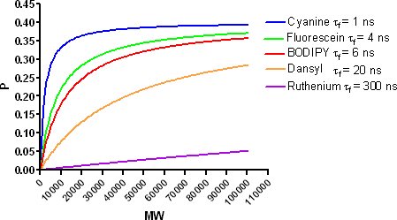
[The graph above contains simulated data using the Perrin equation (Cantor and Schimmel, 1980) and taking the limiting polarization as 0.5 using T = 293 K and assuming a spherical protein in water with the fluorescence probe rigidly attached]
Typical fluorophores include fluorescein- or BODIPY-labels that have fluorescence lifetimes allowing FP measurements to be made between a small labeled-ligand (<1500 Da) and a large receptor (e.g. > 10,000 Da).
The increase in polarization can be measured with several microplate readers where the fluorescence is measured using polarized excitation and emission filters. Two measurements are performed on every well. Data is obtained for the fluorescence perpendicular to the excitation plane (the “P-channel”) and fluorescence that is parallel to the excitation plane (the “S-channel”). For screening applications, the millipolarization units (mP) are often calculated using:

The proper use of S and P channel data requires two corrections. First, accurate calculation of polarization using fluorescent readers requires calculation of the instrument “G-factor”. This factor corrects for any bias toward the P channel. For microplate readers, a 1 nM fluorescein solution is typically used and the G-factor that yields a value of 27 mP is entered (27 mP is the known value for a 1 nM fluorescein solution at R.T). Secondly, the S and P values should have the background fluorescence subtracted (determined using assay buffer without labeled-ligand in the well).
Receptor-binding FP assays use a small molecule labeled ligand (so called tracer) and a large unlabeled receptor. An example is a fluorescently labeled-steroidal ligand binding to a nuclear receptor-ligand binding domain (kits of this type are sold by Invitrogen/PanVera). This type of assay typically yields a minimum signal of approximately 50 mP for the unbound tracer and a maximum signal of approximately 300 mP when the tracer is fully bound to the receptor.
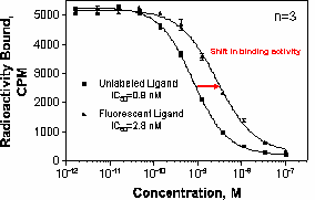
The receptor binding activity of a fluorescent-labeled tracer can be determined in a competition assay using a radiolabeled ligand and traditional methods of receptor binding (filtration, SPA, charcoal precipitation, etc.). As shown in the figure below, some loss of receptor binding activity may occur following fluorescent tagging. It is important to identify lower binding activity prior to further experiments with the fluorescent tracer. Functional receptor assays, such as cAMP measurement, calcium mobilization or GTPγS binding, can also be performed to determine if there has been a loss in biological activity as a result of the labeling process.
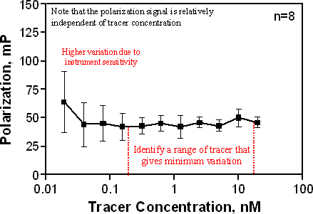
The Kd of the tracer and the amount of tracer bound under the chosen assay conditions will be required for analysis of competitive binding parameters. Typically, the Kd can be estimated using radioligand-binding techniques (SPA, filtration) discussed in previous sections, provided there is not significant deviation in the potency of the tracer and the unlabeled molecule (see figure above). It may be useful to perform a tracer calibration curve by varying the amount of tracer and ensuring that the polarization signal is constant over a reasonable concentration range, inclusive of the estimated Kd. By definition, the polarization signal is independent of the intensity of the tracer. This also identifies the variability at the tracer concentration to be used. The polarization signal as a function of tracer concentration is shown for a representative tracer in the figure below. Note that as the signal nears the limits of sensitivity for the detector, the variation increases.
The amount of bound tracer can be measured in an experiment where the tracer is held at a constant concentration near its Kd and the receptor concentration is then varied. An example of this type of experiment using the glucocorticoid receptor (GR) included in the FP kit available from Invitrogen/PanVera is shown below. Here the ligand-binding domain of GR is varied using a constant Kd concentration of a labeled-steroidal ligand (Fluormone™, Invitrogen/Panvera kits; Data provided by Pharmacopeia).

In these types of FP experiments no correction for nonspecific binding (NSB) is performed as was shown in earlier sections for radioligand-binding experiments. This is because the tracer (what is the radioactive ligand concentration in traditional assays) is held constant at a concentration usually near the Kd and the protein receptor concentration is then varied over several orders of magnitude. However, this assumption should be checked by observing the polarization of the ligand in the absence of receptor. (Caution: it is possible to observe increasing FP signals when membrane receptors are used due to light scattering. In those cases, a correction may need to be made by measuring the signal in the presence and absence of the fluorescent tracer). If binding to non-specific buffer components or microtiter plates surfaces is observed then this tracer should be avoided. An analytical treatment of FP competitive-binding data has recently been presented by Roehrl et al. (2004) that allows one to quantify the effect of non-specific binding on FP titration curves.
Examination of the curve above allows one to choose a receptor concentration that yields an acceptable assay window (typically a ΔmP of between 150 mP and 300 mP).
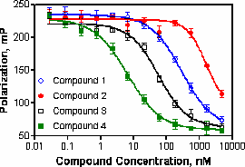
Sensitivity to known competitors should be checked at this stage to ensure that the developed FP assay is adequate for the intended purpose. An example pharmacological profile using fluorescence polarization is shown below.
The FP assay format is homogenous in nature and therefore lends itself to simple “mix and read” protocols. However, to obtain an acceptable signal, the assay must be set-up with a large fraction of the tracer bound to the receptor (typically >80 %). The high amount of bound tracer requires a specific set of equations to be used when interpreting FP derived competition binding results.
In these cases, where a large amount of bound tracer exist, the Cheng-Prusoff equation as mentioned in the discussion of heterologous competition-receptor binding (see p. 27) will always lead to an overestimation of the Ki from the IC50. This is because the Cheng-Prusoff equation is strictly given as:

{Eq. 1}
In the case of FP displacement-binding, the free ligand term [Lf] can not be substituted for the total ligand concentration [L] because there is little free ligand available. This differs from the typical saturation-binding experiments mentioned in previous sections.
Three equations have been presented in the literature to provide a solution to this situation for simple competitive-binding. Munson and Rodbard (Munson and Rodbard, 1988) provide a correction that takes into account the amount of bound tracer. This takes the form of:

{Eq. 2}
Where yo is the bound/free ratio of tracer and Lo is the total tracer concentration.
Huang provides an alternative form of this correction in terms of the fraction of bound tracer (Huang, 2003). Rearrangement of Equation 15 given in Huang to solve for Ki yields:

{Eq. 3}
Where Fo is the fraction of tracer bound and Lo is the total tracer concentration. Huang’s result is redundant with the earlier Munson and Rodbard equation except for expressing the equation in terms of the fraction of tracer bound. Therefore, Eq. 2 and Eq 3 yield the same correction (see below).
The final correction often used in this situation is the one derived by Kenakin (1993). Here the equation is expressed in terms of total receptor concentration (Ro), the total tracer concentration (Lo as above) and the bound tracer concentration (Lb).
{Eq. 4}
These equations should be used instead of Cheng-Prusoff when > 10% of the tracer is bound to the receptor in the assay.
Application of Ligand Depletion Equations
Once a suitable choice of receptor and tracer concentrations have been made and the resulting assay has been shown to be useful for competitive binding analysis, one can calculate the amount of bound tracer under the assay conditions taking the lower and upper asymptotes as values for free and bound tracer respectively.
Some example competition-binding data (Fluormone™ kit, Invitrogen/Panvera) are shown in Table I to illustrate the differences between using the Cheng-Prusoff equation without correction for the amount of bound tracer or each of the above equations which correct for tracer depletion. For these competition-binding experimental results the conditions were:
- Equilibrium dissociation constant, Kd = 0.6 nM (Fluormone™ ligand), determined using saturation binding analysis.
- Bound Tracer Concentration, Lb = 0.9 nM, determined from receptor concentration experiment at constant tracer (Lo), by reading the mP signal and determining the % of maximum
- Total Tracer Concentration, Lo = 1 nM, concentration set near the Kd value
- Total Receptor Concentration, Ro = 4 nM (GR ligand-binding domain), determined from receptor concentration experiment at constant tracer – yields statistically valid assay with robust signal
These concentrations yield the following terms required for Equations 2-4:
- Bound/Free ratio of Tracer, yo = Lb/(Lo – Lb) = 0.9/(1-0.9) = 9
- Fraction of Tracer Bound, Fo = Lb/Lo = 0.9/1 = 0.9
Table I. Comparison of Ki values determined from ligand depletion correction formulas. Values are in nM. IC50 shown is the measured IC50 under the assay conditions described in the text. All other values are calculated values. Data provided by Pharmacopeia.
|
|
(1)
|
Ki, nM
|
|
Ligand
|
IC50
|
Cheng-Prusoff
|
Munson-Rodbard
|
Huang
|
Kenakin
|
|
Cortisone
|
8.0
|
3.0
|
0.24
|
0.24
|
0.6
|
|
Dexamethasone
|
3.6
|
1.3
|
-0.16
|
-0.16
|
0.3
|
|
Estradiol
|
815
|
306
|
74
|
74
|
63
|
|
Testosterone
|
229
|
86
|
20
|
20
|
18
|
|
Compound 1
|
6.4
|
2.4
|
0.09
|
0.09
|
0.5
|
|
Compound 2
|
1000
|
375
|
91
|
91
|
77
|
A graphical representation of the data is shown below.
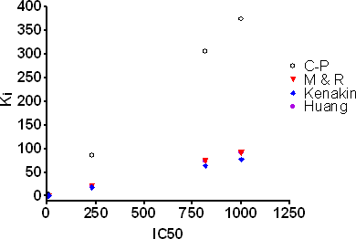
Application of Cheng-Prusoff under these conditions can lead to more than 10-fold overestimations of Ki. In many cases all three equations yield similar corrections and as mentioned above Munson & Rodbard and Huang yield identical values. However, one issue with the Munson & Rodbard and Huang type corrections is that certain combinations of IC50, Kd and bound tracer yield impractical negative values of Ki. This has been discussed in the literature as a breakdown in additional assumptions buried within these equations such as competitive inhibition with a single binding site. For this reason, the Kenakin equation is commonly chosen for performing this correction. Additionally, curve fitting to the equations given in Roehrl et al. (2004) can be used to examine if complete inhibition is achieved as well as the KD of the competitor compound.
All FP experiments start with measuring polarized prompt fluorescence from the assay well. This makes these experiments susceptible to fluorescence interference by compounds present in the well. However, a helpful method to address this issue has been presented by Turconi et al. (2001). This paper calculates the total fluorescence intensity from a well (given by S + 2P; see references in above paper) and the observed anisotropy[1] from the each well to flag false positive wells due to fluorescence interference.
An example is provided below to illustrate the use of this method. Plots of the total fluorescence intensity (normalized to the control well values, e.g. the total fluorescence intensity of the assay in the absence of compounds) versus the anisotropy are shown below.

Three cases are illustrated in the figure above. In case A, the compounds in the wells are not active or fluorescent. Therefore the measured Fluormone tracer is bound to GR ligand-binding domain (GR-LBD) and the anisotropy values are clustered around the 0% inhibition value. Furthermore, there is no change in fluorescence intensity in the compound-containing wells relative to the control wells. In case B, the compounds in the well are active in the assay but not fluorescent. Therefore, the tracer is being displaced from the GR-LBD and the anisotropy values distribute from high to low inhibition values. Again, there is no change in the total fluorescence intensity. In case C, the compounds appear active as they show a decrease in anisotropy values suggesting that the tracer has been displaced from the GR-LBD. However there is a correlation between decreasing anisotropy and increasing fluorescence intensity in the wells with the lowest anisotropy values showing more than a 35-fold increase in the fluorescent intensity relative to control values. This suggests that the measured FP is due to the compounds themselves rather than the tracer.
In typical FP-receptor binding experiments the tracer is kept at a low nM concentration while the compounds that are being screened are typically in the μM range. If these compounds are fluorescent at the detection wavelengths then their fluorescence can easily overcome that of the tracer. As compounds in screening campaigns are typically of low molecular weight (<500 Da) they will exhibit low anisotropy values. Compounds in case C were of this type and subsequent secondary assays showed them to be inactive. A final case not shown above is where the compounds are both fluorescent and active. Turconi et al. present an equation that can be used to fit the fluorescent intensity data to the case where anisotropy changes without displacement of the ligand (see Equation 4 and discussion therein of Turconi et al.). The solid line in case C above shows an example of this fit. One can then evaluate outliers from this curve fit in terms of potential active but fluorescent compounds.
It is also possible to observe changes in polarization that are due to fluorescent compounds present as aggregates. In this case, the fluorescence intensity will increase along with the polarization as long as the aggregation does not quench the fluorescence. Additionally, light scattering from particulates or compound participates can lead to apparently high polarization values. For receptor binding experiments as described above this superfluous increase in polarization may mask any decrease in polarization due to an active compound and thus result in a false negative. Careful examination of the fluorescence intensity versus polarization plots should identify these artifacts.
[1] Anistropy is derived by measuring the S and P channels as described above, however the fluorescence is expressed with the denominator representing the total fluorescence intensity from the sample. The equation for calculating anisotropy is given by:

Anisotropy and polarization are related by the equations given below where P is the polarization and a is the anisotropy:
In general, anisotropy is more useful analyzing complex systems or mixtures as the equations are simpler to express in terms of anisotropy. (Cantor and Schimmel, 1980). Arguably, screening data should be presented in terms of anisotropy rather than polarization but this convention has not been adopted as yet.
- [L] - Radioligand Concentration
- [R] - Receptor Concentration
- [RL] - Concentration of Receptor-Ligand complex
- Kd - equilibrium dissociation constant for radioligand ([RL] yielding Bmax/2)
- Ki - equilibrium dissociation constant for an unlabeled compound
- IC50 - concentration of unlabeled drug which results in 50% inhibition of binding activity
- kon - association rate constant
- koff - dissociation rate constant
- kobs - observed association rate constant
- Bmax - maximum number of binding sites
- NPE - Non-proximity Effects
- NSB - Nonspecific binding
- Ki C-P = Ki Cheng-Prusoff
- Ki T-B = Ki Tight-Binding
- Textbook of Receptor Pharmacology. (2003). Second Edition. Foreman, J.C. and Johansen, T., Editors. CRC Press, New York.
- Kenakin, T. (1997): Pharmacologic Analysis of Drug-Receptor Interaction. Lippincott-Raven Publishers, Philadelphia.
- Receptor Binding Techniques. (1999). Methods in Molecular Biology Series, Volume 106, Keen, M., Editor. Humana Press, New Jersey.
- The Pharmacology of Functional, Biochemical, and Recombinant Receptor Systems. (2000). Handbook of Experimental Biology, Volume 148, Kenakin, T and Angus, J.A., Editors. Springer-Verlag, New York.
- Receptor-Ligand Interactions: A Practical Approach. (1992). The Practical Approach Series. E.C. Hulme, Editor. Oxford University Press, New York.
- Receptor Biochemistry: A Practical Approach. (1990). The Practical Approach Series. E.C. Hulme, Editor. Oxford University Press, New York.
- Motulsky, H.J. Analyzing Data with GraphPad Prism. (1999). GraphPad Software, San Diego, CA. Available at: http://www.graphpad.com/manuals/analyzingdata.pdf
- Limbird, L.E. Cell Surface Receptors: A Short Course on Theory and Methods. (1996). Kluwer Academic Publishers, Boston.
- Winzor, D.J. and Sawyer, W.H. Quantitative Characterization of Ligand Binding. (1995). Wiley-Liss, Inc., New York.
- Lutz, M. W., Menius, J. A., Choi, T. D., Gooding-Laskody, R., Domanico, P. L., Goetz, A. S. and Saussy, D. L. (1996) Experimental design for high-throughput screening. Drug Discovery Today 1(7): 277-286.
- Kahl, S. D., Hubbard, F. R., Sittampalam, G. S. and Zock, J. M. (1997) Validation of a High Throughput Scintillation Proximity Assay for 5-Hydroxytryptamine1E Receptor Binding Activity. J. Biomol. Screen. 2(1): 33-39.
- Sun, S., Almaden, J., Carlson, T.J., Barker, J. and Gehring, M.R. (2005). Assay development and data analysis of receptor-ligand binding based on scintillation proximity assay. Metab Eng. 7:38-44.
- Cantor and Schimmel in Biophysical Chemistry Part II: Techniques for the study of biological structure and function. pp. 454-465. (1980).
- Huang, X., Fluorescence polarization competition assay: The range of resolvable inhibitor potency is limited by the affinity of the fluorescent ligand. J. Biomol. Screening, 2003;8:34-38
- Kenakin, TP (1993) in Pharmacologic analysis of drug/receptor interaction, 2nd ed., New York:Raven p. 483.
- Munson PJ and Rodbard, D: An exact correction to the “Cheng-Prusoff” correction. J. Receptor. Res. 1988;533-546
- Roehrl MHA, Wang JY, Wagner G. A General Framework for Development and Data Analysis of Competitive High-Throughput Screens for Small-Molecule Inhibitors of Protein-Protein Interactions by Fluorescence. 2004; Biochemistry; 43 (51):16056 -16066, 2004
- Roehrl MHA, Wang JY, Wagner G. Discovery of Small-Molecule Inhibitors of the NFAT-Calcineurin Interaction by Competitive High-Throughput Fluorescence Polarization Screening. 2004; Biochemistry;43(51):16067 -16075, 2004.
- Turconi S, Shea K, Ashman S, Fantom K, Earnshaw DL, Bingham RP, Haupts UM, Brown MJB, Pope A: Real experiences of uHTS: A prototypic 1536-well fluorescence anisotropy-based uHTS screen and application of well-level quality control procedures. 2001; J. Biolmol. Screening 6:275-290
- Lin, S, Bock, CL, Gardner, DB, Webster, JC, Favata, MF, Trzaskos, JM, Oldenburg, KR A high-throughput fluorescent polarization assay for nuclear receptor binding utilizing crude receptor extract. 2002, Anal Biochem. 300:15-21
- Lee, PH and Bevis, DJ Development of a homogeneous high throughput fluorescence polarization assay for G protein-coupled receptor binding. 2000, J. Biomol. Screening. 5:415-419
- Banks, P and Harvey, M Considerations for using fluorescence polarization in the screening of g protein-coupled receptors. 2002, J Biomol Screen. 7:111-7
- Do, EU, Choi, G, Shin, J, Jung, W-S and Kim, S-I Fluorescence polarization assays for high-throughput screening of neuropeptide FF receptors. 2004 Anal. Biochem. 330:156-163
- Allen, M, Reeves, J and Mellor, G. High throughput fluorescence polarization: A homogeneous alternative to radioligand binding for cell surface receptors. 2000, J. Biomol. Screen. 5:63-69
- Burke, TJ, Loniello, KR, Beebe, JA and Ervin, KM Development and application of fluorescence polarization assays in drug discovery. 2003, Combinatorial Chemistry & High Throughput Screening. 6:183-194
- Beasely, J.R., Dunn, DA, Walker, TL, Parlato, SM, Lehrach, JM and Auld, DS. (2003) Evaluation of compound interference in immobilized metal ion affinity-based fluorescence polarization detection with a four million member compound collection. Assays and Drug Development Technologies.1, 455-459.
Also see: http://www.invitrogen.com/downloads/FP8.pdf
|


