NASA Web Site! Wind Tunnel Enterprise

Aerothermodynamics Facilities

NASA Langley Research Center


The 15-Inch Mach 6 High Temperature Tunnel is an open-jet facility possesses superior optical access and high temperature capability. It is ideally suited for development and application of advanced non-intrusive optical surface and flowfield measurement test techniques.

Test Section and Performance

Aerothermodynamics Facilities Characteristics

The Aerothermodynamic Facilities Complex


The Aerothermodynamic Facilities Complex is a collection of four hypersonic wind tunnels utilized for basic fundamental flow physics research, aerodynamic performance measurements, and aeroheating assessment, optimization, and benchmarking of advanced space transportation vehicles.

Collectively, they provide a wide range of Mach number, unit Reynolds number, and normal shock density ratio (see table below. The AFC facilities are relatively small and economical to operate, hence ideally suited for fast-paced aerodynamic performance and aeroheating studies aimed at screening, assessing, optimizing, and bench-marking (when combined with computational fluid dynamics) advanced aerospace vehicle concepts and basic fundamental flow physics research.

Operational Experience


The AFC facilities were designed and constructed in the late 1950's and early 1960's. The AFC has contributed to most major hypersonic vehicle programs including the Apollo, Viking, Space Shuttle Orbiter, National Aero-Space Plane, Pegasus XL, DC-X/Vertical Takeoff and Landing Vehicle, X-33/Advanced Technology Demonstrator, X-34/Small Reusable Booster, X-38/Experimental Crew Return Vehicle, Kistler/Small Payload to Orbit Vehicle, Reusable Launch Vehicle, and X-43.

With the renewed interest in planetary and space exploration, the AFC has also contributed in this arena to the development of the Mars Microprobe, Stardust Sample Return Capsule, and Genesis.
15-Inch Mach 6 High Temperature Tunnel

Test Gas Dry Air
Stag. Press. (psi) 50 to 450
Stag. Temp. (R) 940 to 1260
Mach number 6
Reynolds number, per foot 0.5 to 6.0 x10⁶/ft
Dynamic Pressure (psi) 0.8 to 6.8
Shock Density Ratio 5.3
Test Core Size (in) 10 (dia)
Max. Run Time (sec) 120
20-Inch Mach 6 CF4 Tunnel

Test Gas Tetraflouromethane
Stag. Press. (psi) 100 to 2000
Stag. Temp. (R) 1100 to 1480
Mach number 6
Reynolds number, per foot 0.05 to 0.75 x10⁶/ft
Dynamic Pressure (psi) 0.09 to 1.6
Shock Density Ratio 11.8
Test Core Size (in) 14 (dia)
Max. Run Time (sec) 30
20-Inch Mach 6 Tunnel

Test Gas Dry Air
Stag. Press. (psi) 30 to 475
Stag. Temp. (R) 760 to 940
Mach number 6
Reynolds number, per foot 0.5 to 8.0 x10⁶/ft
Dynamic Pressure (psi) 0.51 to 7.6
Shock Density Ratio 5.3
Test Core Size (in) 12 by 12
Max. Run Time (sec) 900
31-Inch Mach 10 Tunnel

Test Gas Dry Air
Stag. Press. (psi) 150 to 1450
Stag. Temp. (R) 1850
Mach number 10
Reynolds number, per foot 0.2 to 2.2 x10⁶/ft
Dynamic Pressure (psi) 0.65 to 2.4
Shock Density Ratio 6.0
Test Core Size (in) 14 by 14
Max. Run Time (sec) 120


Flowfield
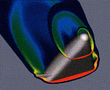
Computational Fluid Dynamic Results of Flowfield Over X-33 Vehicle
Thermographic
Surface Heating Image of X-34 Acquired with Thermographic Phosphor Technique
Data Acquisition and Processing

All AFC facilities have compatible, stand-alone data acquisition systems. The heart of the system is a 128 or 256 channel, 16-bit, 50 or 100kHz throughput rate, amplifier per channel, analog-to-digital NEFF System 620/Series 600. Acquisition and reduction computers are Hewlett Packard 9000 series 745i systems. Macintosh computers are available in all control rooms to aid in the post-run plotting and analysis data. Customer supplied computers can be networked to the data reduction system if desired.
Safety and Design Criteria

Langley?s LHB 1710.15 Wind Tunnel Model System Criteria is the guideline for model design and fabrication. Model installation and any exceptions to this document must have the approval of the 0.3-M TCT Safety Head on a case-by-case basis to assure personnel and tunnel hardware are not exposed to risk.
Model Supports

Test Techniques

All AFC facilities are equipped with hydraulic model injection/support systems. Angle of attack and sideslip ranges are as follows:

AlphaBeta
31" M10-90? to +90??5?
20" M6 Air-5? to +55? ?10?
20" M6 CF4-10? to 50??5?
15" M6 HTT-10? to 50??10?
22" M20 He-10? to 50??5?


Models are typically sting mounted and various dogleg sting holders are available to provide extended angle ranges. Models can also be strut mounted if so desired.

Hyper-X Force
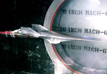
Hyper-X Force and Moment Model Installed in the 20-Inch Mach 6 Air Tunnel
AFC facilities utilize standard water-cooled 6-component strain gage balances and electronically scanned pressure (ESP) systems. Model surface heat transfer rates are measured using thin-film resistance gages, infrared imaging systems, thermocouples, and global two-color thermographic phosphors.

The global two-color thermographic phosphor technique is a patented, nonintrusive means for defining a vehicle aeroheating environment quickly and inexpensively. The technique provides qualitative/quantitative heating data over the entire vehicle and is well suited for studying complex boundary layer transition phenomena and extrapolating wind tunnel data to flight conditions. The technique features rapid, inexpensive model fabrication.

Standard oil flow techniques are used to observe surface streamline patterns. All facilities except the 31-Inch Mach 10 Air are equipped with a Schlieren system.
Test Request Procedures

The first step of the test process is to submit a test request form. The form can be filled out electronically or printed for mailing at the NASA Langley aero Compass website. A posttest questionnaire is also available at this site. Our customers are encouraged to provide feedback to the facility for our continuous improvement process.

Document Version 1.0
Trademark Disclaimer:
The use of trademarks or names of manufacturers in this report is for accurate reporting and does not constitute an official endorsement, either expressed or implied, of such products or manufacturers by the National Aeronautics and Space Administration.
For more information contact:
The Aerothermodynamics Facilities Complex Manager -- NASA Langley Research Center -- Hampton, Virginia 23681-2199
phone: 757 ° 864 ° 5229 | fax: 757 ° 864 ° 8670 | e-mail: wte+ fm_20inm6@larc. nasa. gov

NASA Official Responsible For Content:
Pete Jacobs
Page Curator: CONITS Development Team Date Last Updated:11/17/2005