| NIOSH In-house FACE Report 2004-05 |
May 31, 2006 |
Summary
On February 16, 2004, three male ironworkers (aged 30, 42, and 44 years
old) were killed, and three male ironworkers and two male operating engineers
were seriously injured while working on a bridge construction project.
On February 18, 2004, one of the seriously injured ironworkers died in
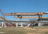
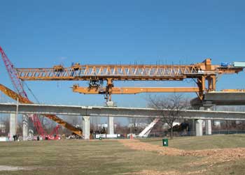
a local trauma center. The incident occurred during the launching and
subsequent catastrophic collapse of a launching gantry (LG) (a horizontal
framework of steel trusses that span the distance between two elevated
bridge piers, designed to lift pre-cast segments of roadway - see photo
below). The LG involved in this incident was positioned on an interstate
bridge construction project. All four victims were performing various
required tasks for launching (re-positioning) the LG when the collapse
occurred. EMS and rescue units were dispatched and arrived within minutes
of the collapse, at which time three of the fatally injured workers were
pronounced dead on scene.
NIOSH investigators concluded that, in order to prevent similar occurrences,
Employers should:
- ensure that the manufacturer’s operating procedures are followed
or provide alternative protective measures such as engineering controls
in order to ensure safe operations.
- ensure that workers comprehend and understand safety training and
safety instructions, and that issues such as language barriers do not
interfere with the effectiveness of the training, particularly when
employees are required to work with unfamiliar equipment.
- develop and implement written standard operating procedures (SOPs)
for unfamiliar equipment, and provide training on the SOPs to all employees
involved in equipment operation.
In addition,
Employers and general contractors should:
- ensure that various components of a construction process are compatible.
State and Federal Occupational Safety and Health Administrations should:
- consider developing requirements for inspecting and certifying cantilever
launching gantries similar to those currently required for mobile cranes.
Introduction
On February 16, 2004, three male ironworkers (aged 30, 42, and 44 years
old – victims #1, #2, and #3) were killed, and three male ironworkers
and two male operating engineers were seriously injured during the launching
and subsequent collapse of a 1.8 million pound launching gantry (LG).
On February 17, 2004, the National Institute for Occupational Safety
and Health (NIOSH), Division of Safety Research (DSR), became aware of
the incident through national media coverage. On February 18, 2004, one
of the seriously injured ironworkers (victim #4) died in a local trauma
center from his injuries. On February 23-27, March 2-5, March 7-10, and
April 13-15, the DSR Chief of the Fatality Investigations Team and a DSR
Safety Engineer conducted an investigation of the incident. The incident
was reviewed with: the Corporate Safety Director for the general contractor
(GC) of the bridge project; officials from the state Department of Transportation
(DOT) who managed the bridge construction project; representatives of
the local unions including the ironworkers, operating engineers, and carpenters;
consulting engineers investigating the incident for the state DOT and
the GC; and officials of the local area office of the U.S. Occupational
Safety and Health Administration (OSHA). The scene was photographed and
measurements were taken. Meetings and interviews were conducted with the
GC’s representatives, the local fire and police department, and
employees, including members of the local ironworkers, operating engineers,
carpenters union, and surveyors that were on site prior to or during the
incident. A meeting was also held with the LG manufacturer’s representative.
Daily inspection checklists, the manufacturer’s LG erection manual,
copies of the state OSHA On-Site Consultation Program safety surveys,
photographs, the employer’s site-specific safety and health procedures
manual, and the county coroner’s reports were reviewed. The safety
equipment worn by the victims was examined at the county coroner’s
office.
Employer
The GC involved in the incident employed approximately 240 workers at
the site at the time of the incident. The GC had been in business for
more than 125 years, and had performed construction work on large engineering
construction projects, including civil, power and industrial facilities,
buildings, roads, and bridges. The GC was a division of a larger corporation
that employs approximately 2,800 employees worldwide. This was the GC’s
second fatal incident since 1992, when one worker was killed on a different
work site.
The GC had a site-specific safety and health procedures manual for the
jobsite, including fall protection, crane operations, and various other
site specific operations, and employed a full-time safety and health coordinator
on the site. Prior to this incident, the GC had experienced five lost-time
injuries during the 1.3 million man-hours worked on this site. Each employee
completed a mandatory 2 hour safety orientation prior to beginning work,
which consisted of a video, oral presentation, and a question & answer
session.
On March 10, 2003, the GC voluntarily entered into a safety partnership
specific to this site with the U.S. Occupational Safety and Health Administration
(OSHA), the state DOT, the state Civil Service Employees Association,
the state OSHA On-Site Consultation Program,a
the state Contractors Association, and contractors and labor union locals.
The partnership was designed to “expand the OSHA’s reach into
the project, allowing OSHA to work with the companies involved to promote
safety programs, management systems, and work with the methods utilizing
the latest technologies and safest available methods.”1
All subcontractors on site were required to have an effective safety and
health program, be in compliance with applicable OSHA regulations, and
agree to provide safety and health records for evaluation–including
injury and accident reports. The partnership was comprised of representatives
from all partners working on or associated with the project.
Each skilled trade and subcontractor had a representative on the partnership
committee, and the GC, state DOT, Federal OSHA, and state OSHA on-site
consultation program each had up to two representatives on the committee.
As part of the partnership effort, the committee reviewed safety and health
compliance issues at the site on a bi-monthly basis, analyzed job site
audits, made partnership improvements, and evaluated partnership modifications,
achievements, and successes in an effort to improve safety. In addition,
a subgroup of partners performed audits of the jobsite that included monthly
checklists. The audit team consisted of a project safety representative
from each of the following partners: the GC, the state DOT, the subcontractors,
and the state OSHA On-site consultation program.
Equipment
There were two, 315 foot-long, “twin” LGs (designated LG1
& LG2) on this site that were designed to perform the work of lifting
pre-cast concrete roadbed (bridge) segments, each 10 foot x 60 foot and
weighing between 75 – 100 tons, into place to form each span between
adjoining piers of an elevated roadway. (Note: for the purpose of
this report, a “span” is the length of bridge between two
piers). The LGs were designed and built specifically for this construction
project. The LGs were being used side-by-side on the bridge approaches.
Each LG had a structural capacity of 1,650 tons. The rated lifting capacities
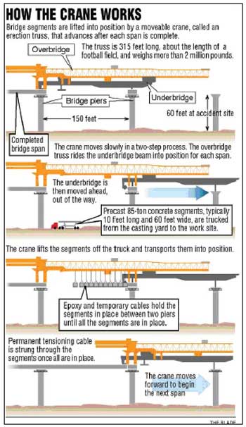
were 1,000 tons. After each span’s completion, the LG overbridge
was moved forward into position to erect the next span, and then secured
to the next pier. Then, the underbridge was moved to the next pier beyond
that one, and secured, before hoisting the new span. A basic process of
launching and hoisting the new span can be viewed in Diagram
1.
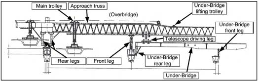
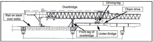
The major components and positioning of the LG at the hoisting position
can be seen in Figure 1. The average time for a complete
launch (move) between piers was about 6-7 hours. The average time to launch
the LG and lift the next span was about one week.
|
Diagram 1. Depicts the basic LG or “launching
gantry” operation.
(Courtesy of the Toledo Blade Newspaper)2
|
|
Figure13.
Main components of the cantilever launching gantry. (Courtesy
of the General Contractor) |
Training
All of the victims received extensive apprenticeship training prior to
this incident through their respective trade unions’ apprenticeship
programs. The only training or experience any of the employees had on
the operation of the LG had been provided on-site by the Italian manufacturer’s
representatives during the assembly and initial-launch phases. None of
the employees reported having any previous experience working with or
on this type of equipment. It was stated by interviewed workers that the
manufacturer’s representatives, who trained the operators and iron
workers, spoke Italian and only broken English, resulting in difficulty
in interacting and understanding conversations. It was also reported that
the manufacturer’s representatives were present for and observed
the 125% load test and three subsequent launchings of the LGs.b
Personal Protective Equipment
All employees at the job site were required to wear hard hats, hard-toed
shoes, eye protection and hearing protection. A fall protection program
was in place that required employees working at elevations or near hazardous
areas to wear the proper fall protection. The victims were wearing the
appropriate personal protective equipment at the time of the incident.
Weather
The weather conditions at the time of the incident included a temperature
of approximately 32 degrees F., calm winds, and no precipitation.
a A part of the Occupational Safety and Health Bureau of the state Department
of Commerce, the OSHA On-Site Consultation program is a free service to
the state’s private sector employers, funded 90% by Federal OSHA
and 10% by the state. Employers can find out about potential hazards at
their work sites, improve their occupational safety and health management
systems, and even qualify for a one-year exemption from routine OSHA inspections.
b The 125% load test consisted of hoisting and suspending bridge segments
from the LG until the total suspended load was approximately 125% of the
rated capacity or 1250 tons.
Investigation
The bridge project involved in this incident was a part of the largest
public works project in the state’s history. The bridge project
began on March 25, 2002, when the contractor mobilized on site. The bridge
construction plans included the assembly of pre-cast concrete segmental
spans, elevated approaches and ramps, and a pre-cast cable-stayed main
span. The construction plans covered the casting of individual bridge
segments on site. The bridge design called for 6-lanes (three lanes in
each direction), with a single center pylon with glass and cable stays
that would fan out like two large sails from the mast of a sailboat. When
completed, the 1,225 foot-long main span was designed to carry an interstate
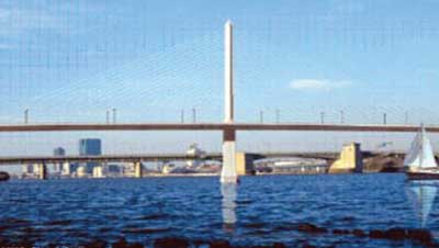
freeway about 130 feet above a river (Photo 1).
|
Photo 1. Artists rendition of the finished
bridge. (Courtesy of the Ohio Department of Transportation,
District Two) |
The construction also included 7,277 feet of approach freeway on elevated
piers (including the incident site) and 5,600 feet of entrance/exit ramps
leading up to the bridge. The project plans estimated using 186,000 cubic
yards of concrete – much of it pre-cast, bridge and elevated roadway
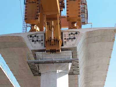
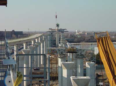
segments (Photo 2) and piers (Photo
3), as well as 3,900 tons of steel post-tensioning cable and 14,000
tons of epoxy-coated reinforcing steel.4
Overall, the bridge assembly would include over 3,000 pre-cast concrete
segments. At the time of the incident, the project had been on track for
completion 14 months ahead of the scheduled completion date of mid-2006.
LG Assembly
LG1 and LG2 were ordered from an Italian manufacturer on May 5, 2002,
and component parts were shipped to the site in large cargo boxes between
January 22, 2003 and April 4, 2003. The LGs were assembled between February
19 and July 16, 2003. It was noted by interviewed employees, DOT representatives,
and the GC management that both of the LGs were difficult to assemble.
It was also noted that some of the sub-assemblies of the LGs did not readily
fit together, due to bolt-hole misalignment. Additional bolt holes and
other modifications were required to be made on-site in order to achieve
assembly. Manufacturer representatives were present and observed the assembly
operation, including modifications. In addition, catwalks, which were
not part of the original design specifications, were installed for employee
protection while working on the elevated LGs. LG2 (the gantry involved
in the incident) was placed in service on September 13, 2003, after the
125% load test was conducted. The 125% load test was successful and uneventful.
LG2 Launches and Section (span) Data
The activity of LG2 prior to the date of the incident showed that it had
successfully launched and lifted 11 spans of bridge into place, as depicted
below:
| #1 - 08/25/03 |
9/13/03 |
130’ |
| #2 - 09/18/03-09/23/03 |
9/26/03 |
145’ |
| #3 - 10/07/03-10/08/03 |
10/9/03 |
144’1 3/16” |
| #4 - 10/18/03-10/20/03 |
10/22/03 |
145’1 13/16” |
| #5 - 10/29/03-10/30/03 |
10/31/03 |
145’ |
| #6 - 11/07/03-11/10/03 |
11/11/03 |
130’ |
| #7 - 11/15/03-11/16/03 |
11/19/03 |
129’9 3/8” |
| #8 - 12/1/03-12/04/03 |
12/06/03 |
143’3/8” |
| #9 - 12/15/03-12/17/03 |
12/18-12/20/03 |
135’7 1/8” |
| #10 - 01/05/04 |
01/09/04 |
135’11/16” |
| #11 - 01/19/04-02/02/04 |
02/03/04-02/07/04 |
135’6 3/8” |
|
Photo 2. Pre-cast bridge segments in place
at end of completed roadbed. The rear legs and underbridge of LG1
are visible at top of photo. Note the horizontal lines
on the bottom of the completed bridge which indicate individual
precast segments.
|
|
Photo 3. Cast-in-place concrete piers
ahead of collapse site.
Photo is facing north. |
The segments in each span varied in size and weight, depending on the
use of the segment. Approach segments were larger and heavier than a segment
that was to be used for a ramp; main span segments for the actual bridge
portion were the largest and heaviest. On average, each approach and main
span segment was approximately 10 feet long, 58 feet wide and 9 feet 2
inches in depth. Any one segment weighed between 75-100 tons. The span
that was to be lifted into place after the 12th launch was 135’6
¼” in length. The grades of launch in relation to level ground
for spans 1 - 6 were 4%, and spans 7 - 12 were 1%.
Operator’s Manual
The GC provided NIOSH investigators a Cantilever Launching Gantry Operator’s
Manual3 Instruction Portion, illustrating the launching process, for review.
(34 pages of English text and 67 pages of instructional diagrams). The
manual was an English translation of the original, Italian manual. The
manual was not requested by, or provided to, the operating engineers or
ironworkers by the manufacturer or the GC. It was noted that the launch
procedures varied depending upon the type and length of span, the type
of pier the gantry was landing on, and the type and length of segments
to be lifted.
LG Operation / Employee duties
Typically, a total of 10 employees were used during gantry operations
– one operator, one foreman, and 8 ironworkers. On the day of the
incident, there was a foreman, an operator, and 7 ironworkers, with the
eighth ironworker having left early due to illness. Although there were
9 employees instead of 10 at the time of the incident, this was not believed
to be a factor in this incident. The process and employee duties are described
below.
LG Launch Sequence
The following launch sequence description is a brief overview of significant
processes and duties of the workers up to the incident, and does not include
all details of the complex process of launching the gantry. The actual
launch processes include a set of very exact and detailed operations.
Launch (Incident)
Once a bridge span between two piers is completed, the LG is readied to
move forward to the next pier. This process is known as “launching.”
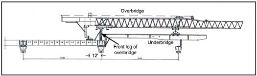
Figure 2 shows the position of the gantry after the
placement of a span.
|
Figure23.
Position of launching gantry at start of launch. Front leg of overbridge
is at end of completed bridge. |
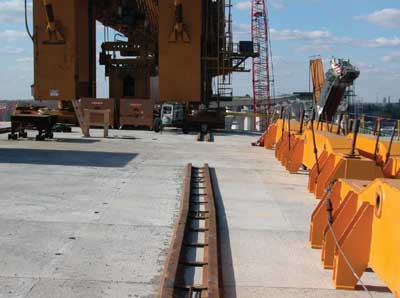
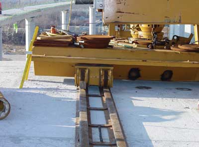
The railway is moved up to the newly completed deck and is positioned
so that the rear legs of the gantry can be moved forward (See Photos
4 and 5).
|
Photo 4. View of the railway system behind
launching gantry LG1.
|
|
Photo 5. Close-up showing roller beam
resting on track. |
At this point, the gantry has been made ready to launch by the ironworkers,
who are stationed strategically around the front leg and the underbridge
to make sure the overbridge is moving freely over the underbridge (no
objects obstructing movement, adequate clearance, cables and hoses free,
etc.).
The operator then activates a button on the operator’s remote control
box, and the drive leg (sprocket and chain system) pulls the overbridge
truss forward on the rails, over the underbridge. It is stopped approximately
12 feet from the end of the newly completed bridge deck - in it’s
new position (See Figure 3).
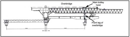
The front leg of the overbridge is disconnected from the bridge deck
by ironworkers, and it is picked up using the main hoist and moved forward
to the next pier with the hoist trolley. (See Figure 4).
The drive leg is used to move the overbridge forward until the front set
of rear legs are in position to line up with the lifting holes of the
last bridge segment. According to the operator’s manual, the front
set of rear legs and the support blocks are to be anchored to the roadbed
by the ironworkers. Note: After the initial load test, the
anchorages were not established. The manufacturer of the LGs provided
anchor points (holes) on the gantries for the sole purpose of anchoring
the LGs to the bridge deck and piers. The GC made the decision to reduce
the number of anchor holes provided in the pre-cast bridge segments with
the holes serving a dual purpose of lifting the segments into place then
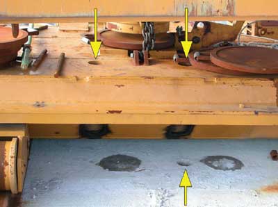
serving as anchor holes. The bolt holes (in the bridge deck and gantry
legs) did not line-up because of the curve in the roadway (see
Photo 6). (This was true for all of
the 11 previous launches.)
|
Figure 33.
Overbridge moved to about 12 feet from the end of the newly completed
bridge deck.
|
|
Figure 43.
The front leg of overbridge is lifted with main trolley hoist and
moved forward to the next pier.
|
|
Photo 6. This photo was taken of LG1’s
position after the incident.
Note the position of the hole in the roadbed relative to the holes
in the
roller beam (top yellow arrows). |
The front leg is positioned over the next pier and is set in place on
two mechanical legs which are extended downward to meet the top of the
pier. The front leg is set plumb so that it is vertical (90 degrees from
the horizontal axis). (Note: in practice, it was discovered
that the front leg was set plumb with a 4 – foot level to within
what was told to investigators as “3 or 4 degrees of plumb,”
and was secured with come-alongs in an attempt to ensure that the leg
did not “tip” or move). The mechanical legs
are then anchored to the pier top by the ironworkers.
The operator then prepares to launch the underbridge. The underbridge
is untied from the piers and made ready to launch by the ironworkers.
The underbridge is lifted clear of the piers by using the main lifting
hoist (at the rear of the underbridge) and the hydraulic jacks on the
driving leg. At this point, any curvature of the projected roadbed across
the next two piers is taken into consideration by rotating the overbridge
toward the inner part of the curve, or “side-shifting.”
The underbridge is moved forward by the sprocket and chain drive system
on the drive leg (Figure 1). Iron workers are stationed
strategically around the front leg and the underbridge to make sure the
underbridge is moving freely as it passes through the front leg structure
(no objects obstructing movement, adequate clearance, cables and hoses
free, etc.). Two of the ironworker victims (victims #1 and
#2) were positioned on top of the underbridge in the area of the front
leg of the overbridge and were performing these duties when the incident
occurred (See Figure 5).
The front leg (Figure 1) of the underbridge is moved
until it is located directly below the two large support rods suspended
from the tip of the overbridge trusses.
The two support rods are disconnected from the underbridge and raised
out of the way, and the underbridge is moved past the front leg and the
pier and then moved backward so that it can be landed in the proper position.
It is at this point that the underbridge can be “side shifted”
to accommodate the curvature in the roadway, and be placed in position
to land on the pier top. Once landed, large bolts are passed through the
base to secure the leg to the pier. Iron workers are stationed around
the top of each pier to guide the underbridge into position and to secure
the legs to the piers. (Note: three of the injured ironworkers
were on a catwalk around the middle pier preparing to perform this function
when the incident occurred. The catwalk and all three injured ironworkers
were dislodged from the pier and fell to the ground below. (See
Figure 5) Also, at the
time of the collapse, ironworker victims #1 and #2 were in position on
top of the underbridge, and victims #3 and #4 were in position on top
of the outer (furthest) pier, directly under the underbridge (Figure
5), waiting for the front leg of the underbridge to come
into position so that they could bolt it to the pier. The operator was
on a catwalk above and behind the front leg, and rode the LG down as it
fell to the ground, suffering serious injuries).
|
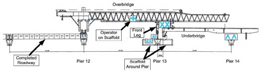
| Figure 53. The underbridge
is moved past the next pier so that the rear leg of the underbridge
can be folded down. The underbridge is then backed up and landed on
the piers. The *s depicts the position of the 3 injured iron workers;
the Xs depict the positions of victims #1 and #2; the ^s depict the
location of victims #3 & #4; and the + depicts the position of
the operator at the time of the incident. (Note: the
injured ironworkers and the operator were standing on catwalks.) |
Possible Collapse Scenarios
The exact cause of the LG collapse could not be determined during this
investigation; however, two plausible scenarios were identified. The scenarios
are hypotheses based on information available at the time of the investigation.
The first scenario considers the 1% grade of the roadbed the LG was setting
on, and the lack of bolting the rear LG legs to the deck. As discussed
above, several of the previous launchings (1-6) were performed with the
rear legs set on a grade of 4%, which would have supplied a greater amount
of backward-force to the rear legs of the LG, and off of the front leg
of the overbridge. When the launches were conducted at a 1% grade, some
of the back-force on the rear legs was transferred to the front leg of
the overbridge, and the LG was subjected to a greater forward force. This
increased forward force may have contributed to the unanchored LG falling
off the bridge deck approximately 65 feet to the ground. In this scenario,
it is unclear why the LG would not have fallen off in an earlier launch.
The second scenario is similar, and possibly more likely than the first.
In this scenario, the greater curvature of the roadway and the positioning
of the piers for landing the LG may have compounded the risks of the un-anchored
rear legs, improperly anchored front leg, and forward force on the gantry
described above. This curvature required the operator to “side shift”
the overbridge and ultimately the underbridge to a greater degree in order
to land the underbridge on the next pier. These factors, working together
with the un-anchored rear legs, could have shifted the center of gravity
and load forces on the front leg to the right (the direction of the side-shift).
The shift may have caused the front leg of the overbridge, which was held
in place by friction forces and the come-alongs, to tilt to the right
and forward, causing the entire structure to slide off the bridge deck
and fall to the ground. It was stated by several witnesses that they heard
a very loud “ping” or “boom,” resembling the sound
of metal snapping, just prior to the LG falling, and that it appeared
that the LG “rolled” to the right as it collapsed. The “ping”
or “boom” sound may have been the come-alongs or bars failing
as the front leg tipped forward and to the right.
In each of these scenarios, it was not possible through this investigation
to definitively determine whether the anchoring of the rear legs to the
bridge deck would have prevented this incident. However, the anchoring
of the rear legs to the bridge deck was a clear operating procedure recommended
by the manufacturer.
Cause of Death
The official cause of death for each victim was determined by the county
coroner to be multiple blunt-force trauma.
Recommendations/Discussion
Recommendation #1: Employers should ensure that the manufacturer’s
operating procedures are followed or provide alternative protective measures
such as engineering controls in order to ensure safe operations.
The manufacturer’s operating manual3
details the final positioning of the overbridge and the front leg as the
following process: The drive leg is used to move the overbridge forward
until the front set of rear legs are in position to line up with the lifting
holes of the last roadbed segment. The main hoist trolley is moved forward
so that the front leg lines up on the next pier. The front
set of rear legs is lowered into position and set on support blocks on
the roadbed. The front set of rear legs and the support blocks are anchored
to the roadbed. The back set of rear legs setting on the roller beam trailer
are repositioned and anchored to the roadbed (4 bars for each leg x 4
legs = 16 bars). In addition, the manufacturer’s procedures
specified that each of the 16 bars was to be pre-stressed to 600 kilo-newtons
(approximately 135,000 pounds) for a combined total of 9,600 kilo-newtons
(approximately 2,160,000 pounds). The manufacturer’s procedures
specified that the front leg was to be anchored to the next pier in a
similar manner with 4 bars. These bars were also specified to be pre-stressed
to 600 kilo-newtons (135,000 pounds) each.
In practice, however, after the initial 125% load test, the positions
of the anchorage holes in the legs were not compatible with the anchorage
holes in the roadbed. All subsequent launches followed the same methodology
and the manufacturer’s procedures for anchoring the LGs were not
followed. According to the GC, drilling new holes in the roadway in order
to facilitate the anchoring was not an option, and it was reported that
the misalignment of the bolt holes became even more pronounced as the
curve in the roadway increased (see Photo 6). The
misalignment of the bolt holes was exacerbated by pre-casting the bridge
segments on site with only half the required number of anchorage holes
per segment. It is surmised that following the manufacturer’s procedures
for anchoring the LGs to the bridge deck as well as providing the proper
number of anchorage holes in the pre-cast segments could have prevented
this incident. It is not known whether using an alternative bolting device
or method of securing the LG to the bridge deck may have prevented the
incident.
Recommendation #2: Employers must ensure that workers comprehend and understand
safety training and safety instructions, and that issues such as language
barriers do not interfere with the effectiveness of the training, particularly
when employees are required to work with unfamiliar equipment.
Discussion: The launching gantries used for highway bridge construction
in this investigation represented a technology that was virtually unknown
to the local workforce prior to their arrival at the work site. While
representatives from the launching gantries’ foreign manufacturer
were present during the assembly and initial launching, communications
between the contractor, the local workforce, and the manufacturer representatives
were reportedly hindered by language barriers. Workers as well as management
reported to NIOSH investigators that it was difficult to communicate with
and/or understand the manufacturer’s representatives due to their
primary language being Italian.
Overcoming these barriers is crucial to providing a safe work environment.
Employers should develop and provide training for workers in a language
that the workers are able to comprehend.5
It was determined during interviews that the skilled trade workers on
site were highly trained in many areas of construction, safety, and equipment
types. However, none of the employees working on the launching gantries
reported ever working with a launching gantry before, and the only training
provided was on-the-job. The operators were not provided copies of the
LG operator’s manual and the manual was not used as training material
during the operator training process. OSHA federal training standards
require the employer to instruct each employee in the recognition and
avoidance of unsafe conditions and the regulations applicable to the work
environment to control or eliminate any hazards or other exposure to illness
or injury.6
To be most effective, formal training should occur whenever new equipment
is introduced into the workplace, and this training should be given by
a person who has the knowledge, training, and experience necessary to
train workers and convey information effectively. This formal training
could consist of a combination of formal instruction e.g., lecture, discussion,
interactive computer learning, videotape, written material, practical
training (demonstrations performed by the trainer and practical exercises
performed by the trainee), and evaluation of worker performance in the
workplace. The evaluation will ensure that the instruction given was understood.
Recommendation #3: Employers should develop and implement written standard
operating procedures (SOPs) for unfamiliar equipment, and provide training
on the SOPs to all employees involved in equipment operation.
According to the manufacturer’s operating manual,3
there were up to 394 steps involved in launching the LG. When operating
such complex equipment, employers should consider developing and providing
operators and other employees working on or around the equipment with
a comprehensive set of operating procedures to be followed while using
the equipment, in addition to comprehensive training. The operating procedures
and training should identify potential consequences of not following the
established procedures. For example, such procedures could have noted
that failure to properly anchor the LG to the bridge deck could result
in instability and possible catastrophic failure. The launching gantry
operators that were interviewed reported that they had never seen or been
provided the operator’s manual.
Recommendation #4: Employers and general contractors should ensure that
various components of a construction process are compatible.
It was determined that properly anchoring each LG was not possible after
the initial launch because insufficient anchorage holes were incorporated
into the pre-cast bridge segments. The LGs were designed to incorporate
a specific process for anchoring both the rear legs and the front leg
of the overbridge prior to advancing the underbridge to the next pier.
The LGs incorporated holes intended for the anchoring bars to pass through
and connect to the bridge segments. According to OSHA, the LG manufacturer
and the GC met and discussed anchorage hole requirements for both the
LGs and the bridge segments several months before assembly of the LGs
began in February 2003. Individual bridge segments were pre-cast on-site
prior to the initial launches of both LGs. These pre-cast segments contained
only half the required number of anchorage holes that were actually the
lifting holes used by the LGs in the hoisting process. Thus, the LGs holes
were not compatible with the pre-cast bridge segments’ holes. Specifically,
it was not possible to follow the manufacturer’s procedures for
anchoring the LGs to the bridge deck because sufficient anchoring holes
were not provided in the pre-cast bridge segments and the lifting holes
that were in the pre-cast segments did not line up with the holes in the
LG structure.
In addition, State and Federal Occupational Safety and Health Administrations
should consider developing requirements for the inspection, safe operation,
and operator certification of cantilever launching gantries, similar to
those currently required for mobile cranes.
Discussion: Launching gantries represent a new technology which to date
has not been widely used in the United States. While launching gantries
have similarities with mobile cranes (the ability to hoist and position
a load, as well as being self-propelled), they are designed for one specific
task – to position individual roadbed segments during bridge construction.
Since the majority of the U.S. workforce is unfamiliar with launching
gantry technology; equipment assembly; operation and maintenance, oversight
of these activities is necessary to ensure safe launching gantry operation.
This oversight should be no less stringent than regulations covering mobile
crane inspection, operation, and maintenance.
Currently, there are no federal OSHA regulations requiring the certification
of cranes, derricks, and material handling devices used solely in general
industry (covered under 29 CFR 1910.179 and 1910.1807) or used solely
in construction (covered under 29 CFR 1926.550) – which is directly
applicable to the job site in this investigation. Current OSHA regulations
(29 CFR 1926.550(a)(5)) require the employer to designate a competent
person who shall inspect all machinery and equipment prior to use, and
during use, to make sure it is in safe operating condition. Additionally,
29 CFR 1926.550(a)(6) requires that a thorough annual inspection of hoisting
machinery be made by a competent person, or by a government or private
agency recognized by the U.S. Department of Labor and that the employer
must maintain a record of the dates and results of these inspections.7,
8 OSHA has proposed changes to 29 CFR 1926.550
that include crane operator certification by either a crane operator testing
organization approved by a nationally recognized accrediting agency, or
the employer’s own qualification program which must be audited by
a testing organization approved auditor.9
Additionally, OSHA does have an example of certification requirements
for an impartial inspection of certain maritime cargo handling devices
specifically required to be certified under the OSHA maritime safety and
health standards. These standards are found in 29 CFR 1915 (Shipyards),
29 CFR 1917 (Marine Terminals), and 29 CFR 1918 (Long shoring). Third
party applicants are granted accreditation to perform certification functions
required under OSHA’s Cargo Gear Certification Regulations found
in 29 CFR 1919. Currently, only certain types of material handling devices
used in specifically designated maritime operations are required to be
certified. For example, Shipyard Regulations 29 CFR 1915 requires the
certification of derricks and cranes which are part of, or regularly placed
aboard barges, other vessels, or on the wing walls of floating dry-docks
and are used to transfer materials or equipment to a vessel or dry-dock.10,
11 Permanently installed cranes and derricks
on vessels classified as “uninspected vessels” or “commercial
uninspected fishing vessels” (46 CFR Part 28) by the U.S. Coast
Guard must be certified by OSHA-accredited persons. Cranes and Derricks
permanently installed on these vessels must be thoroughly examined and
tested before being put in service initially, thoroughly examined every
12 months, and thoroughly examined and retested at least every 4 years
in accordance with 29 CFR Part 1919 requirements. Similarly, mobile cranes
that are placed on barges and used for purposes of shipyard employment
must be certified by OSHA-accredited persons. These cranes must be thoroughly
examined and tested before being put in service initially, thoroughly
examined every 12 months, and thoroughly examined and retested at least
every 4 years in accordance with 29 CFR Part 1919 requirements.11
In addition, several states including Alaska, California, and Washington
have their own requirements for crane certification.
Regulated inspection and/or certification of the launching gantries throughout
the assembly, initial launch, and bridge construction process as well
as operator certification, could have identified a number of instances
of failure to follow the manufacturer’s operational procedures.
This, in turn, could have identified the failure to properly anchor the
launching gantry during the launch process. The identification of the
failure to properly anchor the legs of the overbridge as a hazardous work
practice may have identified the lack of sufficient anchorage holes in
the pre-cast bridge segments as another failure to follow recommended
procedures. Better inspections throughout the construction process may
have prevented these fatalities.
Investigators
This investigation was conducted by Robert E. Koedam, Chief of the Fatality
Investigations Team, and Timothy Merinar, Safety Engineer, with the NIOSH,
Division of Safety Research, Surveillance and Field Investigations Branch.
References
- OSHA [2003]. Partnership: Maumee River Crossing Project. Toledo,
Ohio: U.S. Department of Labor, Occupational Safety and Health Administration
(OSHA).
- Wilkinson M., Patch, D. [2004]. Quest for answers begins; Tragedy
halts bridge work as safety concerns addressed. Toledo Blade Newspaper,
February 18; sect. A:4 (col 5).
- Employer [2003]. Approach Truss (Cantilever Launching Gantry)
Erection Manual.
- Patch, D.[2004]. Bridge project likely to be delayed for months. Toledo
Blade Newspaper, February 17; sect. A:5 (col 1).
- NIOSH [1998]. Hispanic
Pipe Layer Dies After Being Struck by Excavator (Track Hoe) Bucket on
Construction Site - South Carolina. Morgantown, WV: U.S. Department
of Health and Human Services, Public Health Service, Centers for Disease
Control and Prevention, National Institute for Occupational Safety and
Health, Fatality Assessment and Control Evaluation (FACE) Report 2003-12.
- US DOL [2006]. Title 29, Code of Federal Regulations, 1926.21(b)(2).
Occupational Safety and Health Administration. Safety Training and Education.
http://www.osha.gov/pls/oshaweb/owadisp.show_document?p_table=
STANDARDS&p_id=10607. Washington DC: US Department of Transportation.
Accessed March 2006.
- CFR. Code of Federal Regulations. Washington, DC: U.S. Government
Printing Office, Office of the Federal Register.
- OSHA [2004a]. OSHA Standard Interpretations. 02/01/1993 – Inspection
of cranes used at a construction site.
[http://www.osha.gov/pls/oshaweb/owadisp.show_document?p_table=
INTERPRETATIONS&p_id=21009 ]. Date accessed Dec. 20, 2004.
- OSHA [2004b]. OSHA Trade News Release. 07/13/2004. Consensus reached
on recommendation for OSHA Cranes and Derricks standard.
[http://www.osha.gov/pls/oshaweb/owadisp.show_document?p_table=NEWS_
RELEASES&p_id=10938] Date accessed April 27, 2006.
- OSHA [2004c]. Explanation of OSHA’s cargo gear accreditation
& certification program. [http://www.osha.gov/dts/maritime/compliance/1919_explan_jn.html]
Date accessed: December 20, 2004.
- OSHA [2003]. OSHA Directives CPL 02-01-039 through CPL 2-1.39. Enforcement
of cargo gear regulations and the requirements for gear certification
in the maritime program.
[http://www.osha.gov/pls/oshaweb/owadisp.show_document?p_table=
DIRECTIVES&p_id=2975] Date accessed April 27, 2006.
|