Investigation: # 03MI053
Farm Owner Crushed Underneath Rotary Mower While Changing Blades and Untangling Wire Wrapped On Cutting Blades
|
|
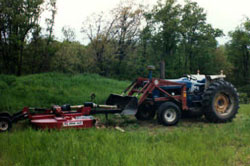
| Figure 1. Incident Scene |
RECOMMENDATIONS
INTRODUCTION
On Monday, May 26, 2003, a 56-year-old horse farm owner was killed when he was crushed under a rotary mower while changing the cutting blades. MIFACE researchers were informed of the farm work-related fatality by a newspaper clipping. On November 17, 2003, MIFACE researchers interviewed the victim’s wife and viewed and photographed the area where the incident occurred and the rotary mower. During the course of writing this report, the medical examiner’s report, death certificate, police department report, and relevant sections of the Bush Hog Model 3210 operator's manual were obtained. Figure 1 and Figure3 are photographs taken at the scene by the responding police department. Figure 2 was taken at the time of the MIFACE farm visit.
The victim owned several commercial stores and had owned the horse farm where the incident occurred for 10 years. The horse farm consisting of 65 acres had 20 horses. In addition to the horse farm, the victim raised hay on another 80 acres that was cut and baled by another farmer. The victim had been active in horse breeding for 30 years and was very experienced operating and repairing farm equipment. The farm did not have a written health and safety plan.
INVESTIGATION
The victim was working on a Bush Hog Brand Rotary Cutter Model 3210. According to the manufacturer’s literature found on the Internet, the rotary cutter had a 10 ½ - foot cutting width and weighed 2,741 pounds. The Ford tractor he used to lift the mower was equipped with a 7600 Bush Hog Brand front-end loader/bucket. A few days prior to the incident, when using the tractor and mower, the mower ran over some fence wire. The wire became entangled in the mower blades and the victim parked the mower in a field. The ground where he left the mower was covered by a layer of what appeared to be fine mortar sand.
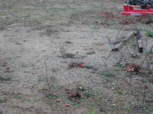 |
Figure 2. Location of mower while
being repaired |
According to his wife, the victim normally did all maintenance and repair on the mower outside of the utility barn on a concrete pad. When he worked under the mower the victim propped up the mower with the loader bucket, chained the mower to the bucket and used boards and posts to keep it off the ground. His wife stated that he normally did the mower maintenance. Often, his wife would assist him because it required a great deal of strength to apply torque to the blades to remove them. The Bush Hog model 3210 operator's manual specified that the nuts on the blade bolts were to be tightened to 450 ft./lbs.
On the day of the incident, the victim had performed several tasks around the farm. In the afternoon, the victim drove the tractor to the location of the rotary mower. He took with him a sharpened set of mower blades. His wife had advised him earlier in the day that she wanted to assist him. He was working alone and the incident was unwitnessed.
The following two possible event scenarios have been developed after interviews
with the deceased’s wife and the responding police agency. Figure
3 shows the pieces of wood that were thought to be used as supports for
the mower.
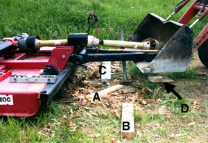 |
Figure 3. Wood used for mower support |
Scenario 1: The mower was positioned in loose soil resembling mortar sand. Using the front-end loader bucket on the tractor, the victim raised the front of the mower by placing the bucket under the mower tongue. He placed one piece of treated timber under the tongue toward the front of the tongue (A), and two pieces of untreated timber (B&C) one under each corner of the mower. He may have used the square piece of wood (D) as a support for the wood under the tongue. The responding police measured the treated timber (A) under the tongue; 5-inches by 3-inches and 31 ¾ -inches long. The size of timbers (B&C) was not measured, nor was the square piece of wood (D). He did not block the trailing wheels to avoid wheel movement. It does not appear that the jack stand seen in Figure 3 was used as an additional support structure. After securing the mower in its raised position, he backed the tractor about four feet away from the propped up mower, leaving the bucket raised about five feet from the ground and the engine in “idle”.
Scenario 2: The mower was positioned in loose soil resembling mortar sand. Using the front-end loader bucket on the tractor, he raised the front of the mower by placing the bucket under the mower tongue. The mower tongue was kept in the raised bucket as a primary support point. The tractor was left in “idle” to maintain hydraulic pressure. The parking brake on the tractor was not set. The timber was placed under the mower and tongue as described in Scenario 1. The mower’s trailing wheels were not blocked.
After propping up the mower as described in scenario 1 or 2, he began to work under the mower. Using a socket wrench, he had partially removed some dull blades. Possibly while exerting torque to remove the nuts holding the blades to the mower, the timber supporting the mower shifted. With the timber shifting in the loose soil, the mower rolled back a short distance completely dislodging the support timbers resulting in the mower fell on the victim’s chest. Police found indentations in the soil where it appeared that the mower wheels had been resting for a period of time. The police measured from these indentations to the final resting point of the mower’s rear support wheels. The mower rolled approximately 46 inches away from the tractor because there is no indication that the tractor moved. The victim was pinned to the ground under the front end of the mower. If Scenario #2 occurred, vibration from the idling tractor in addition to the torque exertion may have dislodged the unsecured mower tongue from the bucket, causing the mower to fall against the timber, dislodging the timber and causing the mower to fall to the ground.
When the victim did not return to the house, the victim’s wife and daughter
drove around the property looking for him. When they arrived at the incident
site, they found the tractor running in “idle” about four feet away
from the mower, with the bucket raised about five feet in the air. There was
a chain that appeared to be unused in the bucket. There were blades and nuts
on the ground but whether they were the sharpened blades he brought with him
or the mower blades he was replacing is unknown. The victim’s wife directed
her daughter to go to the house to call 911 while she tried to free the victim.
The victim’s wife attempted to raise the mower by placing the bucket under
the mower’s tongue. She was unable to do so. Emergency response arrived,
removed the victim from under the mower and took him to a local hospital where
he was declared dead.
After the incident, the family sold the large mower and replaced it with a smaller
one.
CAUSE OF DEATH
The cause of death as stated on the death certificate was hypoxia secondary to chest crush injury. Toxicological tests were not performed.
RECOMMENDATIONS/DISCUSSION
Rule 34 (Machine Guards and Devices) of the MIOSHA General Industry Safety Standard, Part 1, General Provisions offers farm owners sage advice. Rule 34, Subpart (12) states that “an employee shall not place his/her body beneath equipment, such as vehicles, machines or materials, supported only by a jack, overhead hoist, chain fall, or any other temporary single supporting means, unless safety stands, blocks or other support system capable of supporting the total imposed weight is used to protect the employee in case of failure of the supporting system.”
When working on a large piece of equipment that is elevated, consideration should be given to the center of gravity of that object. An elevated load is unstable to begin with and an un-level surface will allow the center of gravity of the load to shift more rapidly to the down side. Any movement caused by work being performed on the load could also cause the load to slip off a support, especially if it is not properly blocked or cribbed.
Since changing blades was a routine job, appropriate supports would have been needed often and should have been available.
Always take the time to adequately support an elevated piece of equipment
when performing repairs or adjustments to prevent being crushed. Even
a very small, quick adjustment such as tightening a bolt warrants using appropriate
support methods when you are under raised equipment. Using suitable
supports, such as cribbing and blocking under the raised mower deck could have
prevented this fatal injury. See Attachment A for
further information about cribbing and blocking.
Blocking the wheels prevent the tires from rolling. Blocks and/or wheel chocks
should be selected according to the equipment’s tire size, percent grade
the equipment is being serviced on, the surface conditions and the vehicle’s
weight. It is best to use two blocks/chocks on the weighted axle since the weighted
axle keeps the tire on the ground against the block/chock. If the block/chock
is placed at the unweighted axle, the tire on the unweighted axle can ride up
and over the block. Use blocks/chocks in pairs, one set at each tire. For most
farm equipment even pine timbers will have sufficient strength to keep from
crushing or rolling. Rolling can be a problem on the farm during field repair.
MIFACE recommends 4”x 6” blocking rather than 4” x 4”
to minimize rolling. The 6" blocks also fit more jacks.
Tractor engine idling in neutral can cause vibration in the bucket; this vibration
will be amplified at the bucket. If the victim laid the mower tongue in the
bucket, left the bucket in the raised position with the tractor idling, and
did not chain the mower tongue to the bucket, the vibration at the bucket may
have caused the mower tongue to gradually move from its original location in
the bucket and possibly cause the mower wheels to roll slightly causing the
wood angle bracing to dislodge. Unless recommended by the equipment manufacturer,
the tractor should be turned off and the brakes locked together and set when
working on attached farm equipment. Also, never rely on hydraulic systems to
maintain a tractor’s front-end loader bucket in a raised position.
Because no hydraulic system is immune from failure, individuals should never work beneath any load supported by hydraulics alone. Hydraulic component leakage or failure can mean a loss of system pressure as well as a loss of load-carrying capacity. Some failures are gradual while others occur suddenly. Often farm owners keep equipment idling to try to maintain hydraulic pressure. If pressure loss occurs while a person is working beneath an implement, loader bucket, or anything else supported by hydraulics alone, the person can easily be pinned and crushed.
It does not appear that in this case, there was a loss of hydraulic pressure that caused the mower to come down and land on the victim. The bucket was found in the raised position, not near the ground. It would be unsafe if the mower tongue was placed in the raised bucket and an operator relied on the hydraulics to maintain pressure to keep the mower lifted without adequate secondary supports, as such a system could fail unexpectedly.
REFERENCES
MIFACE (Michigan Fatality and Control Evaluation), Michigan State University (MSU) Occupational & Environmental Medicine, 117 West Fee Hall, East Lansing, Michigan 48824-1315. This information is for educational purposes only. This MIFACE report becomes public property upon publication and may be printed verbatim with credit to MSU. Reprinting cannot be used to endorse or advertise a commercial product or company. All rights reserved. MSU is an affirmative-action, equal opportunity employer. 3/26/04
Attachment A – Cribbing and Blocking
MIOSHA General Industry Safety Standard Part 38 (Hand and Portable Powered Tools), Rule 3839(4) addresses the use of “jacks”. The term “jack” refers to a portable lifting unit rather than a fixed unit (normally a hoist). To properly use a jack, its rated capacity must be permanently marked on the jack and must not be exceeded during a lift. The jack must be set on or against a firm foundation or blocking. If a jack, at the point of contact with the load, can slip, a wood block or nonslip device must be placed between the cap and the load. Importantly, after a load has been raised or moved, it shall be secured by cribbing, blocks or stands before work is started under the supported load (Refer to the standard for the other requirements for the use of jacks and their inspection).
Most jacks are designed to lift heavy objects, not support them. Proper use of a jack involves knowing the weight limit and proper placement of the jack. Once a jack lifts a heavy object, the object must then be supported by either a jack stand or cribbing. A “jack stand” normally refers to a metal adjustable support with a center post that adjusts and side stabilizers that hold the device straight. Cribbing is the process whereby blocks of wood are placed under the object to support it in an elevated position. Supporting elevated objects with jack stands or cribbing ensures stability of the object especially when work has to be performed under the object. Wood selected for blocking or cribbing should be solid, straight and free of major flaws such as large knots or splits and be free of any paint or finish because this can make the wood slippery, especially when it is wet.
Blocking timbers should be used to provide a foundation for heavy loads or jacks when the jack is not placed on a firm foundation. Most jacks are designed to lift a load straight up. This is why it is essential to assure that the surface the load is on is level. Often during field equipment repair operations, the surface is not firm or even. Blocking timbers should be placed so they rest evenly and firmly on the ground.
Cribbing should be used when the equipment must be supported at a height greater than blocking can provide. Cribbing involves placing timber in tiers that run in alternate directions. To place cribbing, raise the load and without placing yourself under the elevated load, place the cribbing under the load. (See Figure 4). Then lower the load onto the cribbing. If using a jack to raise the load, make sure the jack is on a firm foundation (use blocking timbers as required), raise the load to the maximum height the jack can safely lift to, place cribbing, then lower the load.
 |
Figure 4. Example of cribbing |
To contact Michigan
State FACE program personnel regarding State-based FACE reports, please
use information listed on the Contact Sheet on the NIOSH FACE web site Please
contact In-house FACE
program personnel regarding In-house FACE reports and to gain assistance
when State-FACE program personnel cannot be reached.
| To improve the quality of the MIFACE program and our investigation reports, we would like to ask you a few questions regarding this report. | |||
| Please rate the following on a scale of: | |||
| Excellent | Good | Fair | Poor |
| 1 | 2 | 3 | 4 |
| What was your general impression of this MIFACE investigation report? | |||
| Excellent | Good | Fair | Poor |
| 1 | 2 | 3 | 4 |
| Was the report… | Excellent | Good | Fair | Poor |
| Objective? | 1 | 2 | 3 | 4 |
| Clearly written? | 1 | 2 | 3 | 4 |
| Useful? | 1 | 2 | 3 | 4 |
| Were the recommendations … | Excellent | Good | Fair | Poor |
| Clearly written? | 1 | 2 | 3 | 4 |
| Practical? | 1 | 2 | 3 | 4 |
| Useful? | 1 | 2 | 3 | 4 |
| How will you use this report? (Check all that apply) | |
| O | Distribute to employees/family members |
| O | Post on bulletin board |
| O | Use in employee training |
| O | File for future reference |
| O | Will not use it |
| O | Other (specify) __________________________________________ |
Thank You!
Please Return To:
MIFACE
Michigan State University
117 West Fee Hall
East Lansing, MI 48824
FAX: 517-432-3606
Comments:
| If you would like to receive e-mail notifications of future MIFACE work-related fatality investigation report summaries, please complete the information below. | |
| Name: __________________________________________ | |
| e-mail address: ___________________________________ | |
| I would like to receive summaries for reports involving: | |
| ___ Construction | ___ Agriculture |
| ___ Manufacturing | ___ All |

![]()