| Concerns about the present derating factors used for reeled trailing cables prompted researchers at the NIOSH
Pittsburgh Research Laboratory to determine new derating factors (see the table on the right) for reeled coal
mining trailing cables. In particular, the new derating factors focus on mine trailing cables used on shuttle cars, with both round and flat cable
configurations, that are representative of mining industry usage. For more information on this topic contact: Peter G. Kovalchik |
|
||||||||||||||||||||||||
What Are Derating Factors?
The environmental and thermal conditions where a trailing cable is used and the thermal resistance of its insulation determine a cable’s ampacity rating. Cables used on reels on mobile machinery also have a derating factor applied to account for the heating effects of having one or more layers consistently on the reel. The more layers on the reel, the less amperage a cable can handle due to the effects caused by the buildup of heat.
In a mining environment, the electrical requirements for trailing cables used to power mobile mining equipment are contained in Title 30 CFR, Parts 18 and 75. These federal regulations require that trailing cables be electrically rated according to the standards published in the Insulated Cable Engineers Association/National Electrical Manufacturers Association Standards (ICEA/NEMA) Publication NEMA WC58-1991/ICEA S-75-381 Portable & Mine Power Feeder Cables.
These ampacity ratings apply to cables suspended in still air. They must be corrected for ambient temperatures different from
the standard 40°C, and for different numbers of layers of cables on the reels.
Why Develop New Derating Factors?
There are several concerns about the present derating factors used for reeled trailing cables:
- Rubber-insulated cables that have a maximum operating temperature of 60ºC are the basis of the present derating factors. More recently, manufacturers are using ethylene-propylene-rubber with a 90ºC limiting temperature to insulate mine trailing cables. The newer material possesses greater resistance to heat aging than the rubber-insulated materials manufactured 30 years ago./li>
- The derating factors apply for only one to four layers. However, it is common practice for cable reels to store up to ten layers.
- In Australia, cable manufacturers assign separate reel derating factors to round and flat cables (the ICEA makes no distinction). The flat cable should have a higher ampacity rating than the round because there are fewer air pockets trapped between the adjacent cable layers. Small pockets of air between the cable layers inhibit the flow of heat to the surface of the cable mass, causing the cable to run hotter.
These concerns prompted researchers at the NIOSH Pittsburgh Research Laboratory to determine new
derating factors for reeled coal mining trailing cables. In particular, the new derating factors focus on mine trailing cables used on shuttle cars, with
both round and flat cable configurations, that are representative of mining industry usage.
How They Were Developed
NIOSH researchers had to develop a new method for taking undistorted, distributed temperature measurements in the trailing cable while running static and dynamic tests. The new technique involved embedding a fiber-optic cable inside each of the three conductors of the trailing cable during manufacture. The fiber-optic cable serves as both sensor and communication line. Being integral to the cable, there is no need to invasively place thermocouples to gain temperature readings, thus keeping the cable 100% intact. This also allowed for accurate temperature measurements to be taken during static and dynamic tests. The data transmitted by the fiber-optic cable is collected from only one point along the cable, typically at the end where the conductors are exposed for connection to the power source. This information was sufficient to determine temperatures to within +/- 1°C at 1-meter intervals along the entire length of the cable.
 |
| Cross section of a #4 AWG Round G-GC cable with the fiber-optic cable embedded within each of the three conductors |
For the static testing, the researchers wound the fiber-optic embedded trailing cable onto a stationary cable reel and connected it to three programmable current sources. Simulated duty cycles, based on the manufacturer's data, were then run with one to six layers wrapped on the reel. An infrared camera provided surface temperature data for concurrent computer modeling work and for additional error checking of temperature data.
 |
| Shuttle Car 4 Ton Duty Cycle (43 Amps RMS) |
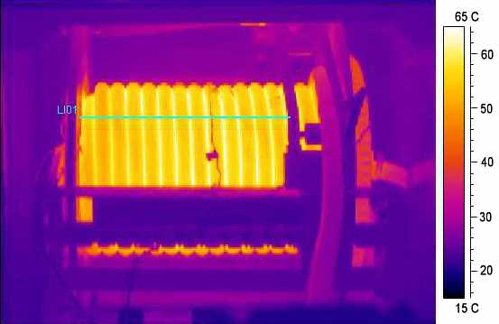 |
| Thermal image of a static 56 Amp test with 2 layers of #6 AWG round cable wound on the reel. |
The researchers conducted four dynamic tests. For each, a shuttle car was driven back and forth over a 27.69 m test track for 8 hours, or until temperature stabilization occurred. The shuttle car was loaded with 6.25 tons of material. A 139 m length of No. 4 AWG round 3 conductor G-GC trailing cable instrumented with fiber optics embedded in the center of each conductor was used to conduct power to the shuttle car, as well as provide a temperature profile. A 74 m length of this cable spanning the distance from the load center to the area near the tie-off point remained in contact with the ground.
 |
| Shuttle Car Test Track Layout |
Test 1: One layer of cable manually wrapped onto the reel, and a second layer spooled on and off the reel as the shuttle car drove over the test track.
Test 2: Two layers of cable manually wrapped onto the reel, and a third layer spooled off and on the reel as the shuttle car was driven.
Tests 3-4: Four and five layers of cable wound permanently on the reel and the fifth and sixth layers, respectively, spooled off and on. Each layer consisted of 15 wraps of cable with layer 1 having 12.9 m of cable, layer 2 having 14.8 m of cable, layer 3 having 17.3 m of cable, and layer 4 having 20 m of cable.