Radio Receivers and Methods to Improve Reception of Weather Radio Broadcasts
Please note: The text and graphics on this page were taken from a National Weather
Service/Central Region publication of the same title. Within the text, there are
references to these graphics. Click the link and the graphic will open in a new window.
In addition, all of the graphics are available at the bottom of this page.
The continuous weather radio broadcasts of the National Weather Service range between the
frequencies of 162.400 megahertz (MHz) and 162.550 MHz. These frequencies are in a band
referred to as Very High Frequency (VHF) that extends from about 50 MHz to around 175 MHz.
The frequencies used by commercial FM radio stations occupy the lower portion of this band.
Also the middle channels of VHF television broadcast in this band. Because of the physical
characteristics and behavior of VHF broadcast signals, it is not uncommon to find owners of
weather radios, like owners of commercial FM or TV receivers, experiencing difficulty
receiving a suitable broadcast even though they are within or near the normal range of the
transmitter.
The typical service area or range of weather radio stations can best be approximated by a
circle having a radius of 40 miles from the transmitting antenna. Technically, the National
Weather Service (NWS) attempts to provide an unobstructed signal level of 8 microvolts to
receiving antennas 6 feet above ground at 95% of all points within a radius of 40 miles from
the transmitter. This is not always possible because of local terrain features such as
valleys, mountains, large buildings, etc. Another factor which could reduce the signal level
is where the transmitting antenna is mounted on the side of the tower (i.e. the top is
already occupied by another antenna). The signal is then reflected off the face of the tower
creating a radio shadow, much the same as a light shadow, on the opposite side of the tower.
Depending on the width of the tower face, antenna height, and transmitter power, the tower
shadow can be quite significant. The NWS office operation the weather radio station can tell
prospective weather radio users if and where such a shadow exists.
Weather radio receivers, both crystal-controlled and tunable, capable of picking up the
weather radio broadcasts, are available in a variety of styles and prices. The price is
usually proportional to the sensitivity and quality of the receiver. Below are listed the
technical specifications to look for when purchasing a radio. The specifications can be
compared to those found in the radio operator's book that accompanies each radio. The
individual radio specifications can usually be found near the front or back of the booklet.
This comparison will help the purchaser make a wise and informed choice of radio. For further
clarification or assistance, a purchaser may wish to consult with a local electronic supplier
or technician. The NWS recommends the public purchase receivers with a 0.5 to 1.0 microvolt
sensitivity for 20 decibels (dB) quieting, a selectivity of 45 to 70 dB down at +/- 25
kilohertz (kHz), tunable or switchable to all frequencies, a warning alarm feature, dual
power source of AC/battery with automatic switchover to battery during commercial AC power
outages, and a collapsible or fixed indoor telescoping antenna with a provision for an
external antenna input connection.
If the owner has a weather radio meeting the general specifications outlined above in proper
working order or a lessor quality radio and still cannot receive an acceptable broadcast, the
cause can usually be found to be:
A) too weak a signal due to distance from the transmitting antenna or loss of signal
penetrating into a building.
B) a geographical or man-made obstruction
C) interference from another station on the same frequency (co-channel interference).
It must be remembered the signal gets weaker the further one gets from the transmitter. The
strength of these signals on the average becomes quite weak at distances greater than 35 to
45 miles. Also, when the receiving antenna is inside a building (not in an open area) some of
the signal will be absorbed and/or reflected by the materials which make up the building
resulting in further loss. Buildings constructed of steel and masonry products usually
attenuate or weaken the signal more than wood or frame construction. Locations below ground
are the worst locations for receiving such a broadcast.
The methods described later are frequently not effective at distances greater than 50-60
miles. Distances on this order and greater are beyond the distance for which broadcast
programming is intended or provided.
Geographical obstructions that cause reception problems are usually mountains, a large ridge
or hills located between the transmitting and receiving antennas. Man-made obstructions may
be classified as large buildings or other structures between the transmitting and receiving
antennas resulting in weak or complete loss or signal. Tower shadows would fall into this
classification. VHF radio transmissions do not bend to any significant degree and generally
follow a line of sight path from the transmitting antenna to the receiving antenna.
Co-channel interference is caused when the receiver lies in or near the fringe area of two
different stations transmitting on the same frequency. If two broadcasts are of nearly equal
signal strength at the receiving antenna, both stations will be detected by the receiver
either causing one to be heard for a few seconds or minutes followed by the other or both
mixing and just being garbled.
For the situations just described, moving the radio to another location can frequently
improve reception. For example, in fringe areas, placing the radio close to a window on the
side of the building from which the broadcast comes will often substantially improve
reception. Sometimes placing it near any window will work. In practically all situations
described above, the use of a properly matched outside antenna will improve reception of the
broadcast.
The illustrations included on this page describe several types of antennas and devices that
could be used to enhance a weather radio broadcast. Some general provisions to keep in mind
are, (a) the range and clarity of reception is dependent upon the antenna height (the higher
the better) and its orientation (toward the desired station), (b) the use of a sensitive and
quality receiver with an antenna assures more reliable and clearer reception, (c) weather
radio transmits a vertically polarized signal, therefore a vertically polarized receiving
antenna (elements up and down perpendicular to the ground) that will receive signals in the
130-175 MHz range will give best reception, (d) at distances up to 30 to 40 miles, a 1/4
wavelength antenna element (18") is suggested; for distances greater than 40 miles a 1/2
wavelength antenna (36") should be used.
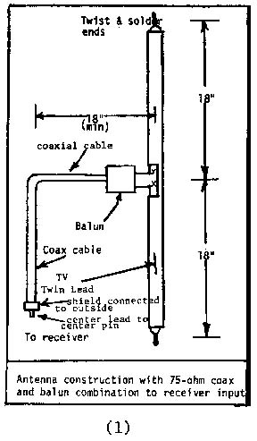
The simplest antenna to construct is called a 1/2 wavelength folded dipole antenna and is
shown as number (1) near the end of this page. The antenna is constructed
from a piece of
flat type parallel TV antenna lead-in. About 1" of insulation is stripped from the two wires
at both ends of a 36" piece of lead-in wire. The ends are twisted together and soldered.
Midway between the ends, one wire is cut and the insulation stripped back a sufficient length
(1") to attach the leads from a balun. A balun is a device that matches the type of antenna
or lead-in to the input of the receiver. Once the connections are made the exposed wires
should be taped. A home made balun is shown in (2) and an inexpensive
commercial model is
shown in (3). The finished antenna should be mounted so the two twisted ends
are straight up
and down as shown in (1). It could be attached to an inside window sill on a
window on the
side of the building from which the signal is transmitted; or better, it should be placed
outside, possibly next to the window or some other convenient location to easily reach the
radio in its most desired location. The lead from the antenna, if it is the parallel flat TV
type, should be twisted once for each foot of lead and extended at a right angle from the
antenna for approximately 18 inches prior to any vertical run.
Another simple antenna to use
in improving the reception of the broadcast is to connect the radio to an existing outside TV
antenna. This procedure is illustrated in (4). This method is usually very
effective when the
TV antenna is constantly pointed in the direction of the desired weather radio station. Also,
this type antenna will help when another station on the same frequency is interfering with
the desired station (co-channel interference). The weather radio frequencies are between TV
channels 6 and 7. Therefore, any TV antenna designed for all VHF TV channel reception will
work very well. Even though the TV antenna is horizontally polarized (elements parallel with
the ground), there is usually enough vertical signal due to scattering and reflection of the
signal that it will significantly enhance the received signal. A device called a band
separator or splitter (5) is attached to the end of the TV lead with one
output connected to
the TV and the other to a balun (2/3) then to the weather radio.
For serious problems in receiving weather radio broadcasts, more sophisticated receiving
antenna systems will likely be necessary. When a home made 1/2 wave length antenna may not be
suitable and an outside TV antenna is not available, a commercially constructed ground plane
antenna (6) with an 18" or 36" vertical shaft is recommended where
directionality is
unimportant. This type of radio receives equally well from all directions.
When directionality is important due to a very weak signal strength, co-channel interference,
or the desired weather radio station being in a different direction from the most often
watched TV station, a specially built antenna (7) or a separate all VHF
channel TV antenna
can be attached to an existing TV mast (8) and permanently pointed in the
direction of the
desired weather radio station. To further improve the signal, the antenna should be mounted
so the elements of the antenna used for the weather radio are aligned vertically to the
ground. The lead-in can be combined with the existing TV lead-in and split (5)
once inside
the building. It would be better, however, for TV/weather radio reception if the lead-ins are
brought separately from the antenna to the radio or TV.
For severe cases of co-channel interference or extremely weak signal areas, a corner
reflector (9) will generally be the only one to provide suitable reception.
The antennas
described here are of the type, which can usually be installed by most people with a minimum
amount of effort, tools, and experience. As a general rule, it is better to use 50-70 ohm
coaxial cable for lead-ins from the antenna to the radios. This type of cable is far less
likely to pickup interference and will offer less resistance to the signal picked up at the
antenna. For further information regarding antennas available in the local areas and specific
instructions for connecting such antennas, a radio dealer or electronic show should be
consulted. They can assist the purchaser to select the best antenna system to match the
specific radio and to solve reception problems.
The costs of the various methods and devices are listed below and are only estimates of
maximum prices, excluding the cost of labor should professional installation be required.
(1) $7-10,
(2) $3,
(3) $5,
(4) $30,
(5) $3,
(6) $30,
(7) $50,
(8) $30,
(9) $175.
As a word of caution, extreme care should be exercised when working with outside antenna
systems. Antennas are usually most stable when mounted along the side of a building then
extended above the roofline. Sloping roof surfaces, ladders, and roof edges are very
dangerous making serious falls possible. Also, support masts or antennas can easily come in
contact with the above ground electrical lines causing potentially fatal shock. If there is
any doubt about one's ability to make an outside antenna installation, professional or
experienced help should be obtained.


|