|
Mack Intelligent Vehicle Initiative
Field Operational Test
Final Report

Foreword
The Federal Motor Carrier Safety Administration (FMCSA) has been engaged in a cooperative agreement to perform field testing of ?Generation Zero? active safety systems as part of the Intelligent Vehicle Initiative (IVI) program since 1999. This Field Operational Test (FOT) focused on an evaluation of a Lane Departure Warning System (LDWS) for large trucks. The purpose of the FOT was to evaluate an LDWS in terms of safety performance and driver acceptance.
LDWS are in-vehicle electronic systems that monitor the position of a vehicle within a roadway lane and warn a driver if the vehicle deviates or is about to deviate outside the lane. LDWS perform this function using forward-looking, video-based systems that process the image to detect the lane boundaries and calculate the position of the host vehicle within those boundaries. The LDWS only provides warnings and does not take any action to avoid a lane departure or to control the vehicle. Therefore, drivers remain responsible for the safe operation of their vehicles.
The experimental plan for the FOT involved installing and utilizing the LDWS on vehicles to collect data during a 12-month test period. To evaluate the system, the data collected during periods with the display on were compared to the baseline data collected with the display off. Data was collected using a specialized system, and uploaded automatically from the vehicles to a project website, which enabled the evaluators to monitor and sort incoming data, as well as change selected reporting parameters.
The information in this document can be used by motor carriers in discerning the viability of LDWS and the functionality of these systems and their integration into the vehicle, which can provide a foundation for future product planning. The carrier who participated in this study had an overall positive experience of LDWS, and drivers found the system to be valuable.
Notice
This document is disseminated under the sponsorship of the Department of Transportation in
the interest of information exchange. The United States Government assumes no liability for
its contents or use thereof.
This report does not constitute a standard, specification, or regulation.
The United States Government does not endorse products or manufacturers. Trade or manufacturers? names appear herein only because they are considered essential to the objective of this document.
Technical Report Documentation Page
| 1. Report No.
FMCSA-MCRR-06-007 |
2. Government Accession No.
|
3. Recipient's Catalog No.
|
| 4. Title and SubtitleMack Intelligent Vehicle Initiative Field Operational Test Final Report
|
5. Report DateMay 2006 |
| 6. Performing Organization Code
|
| 7. Author(s)
Amy Houser (FMCSA), Charles J. Groeller (Mack Trucks, Inc.); Richard Bishop (Bishop Consulting) |
8. Performing Organization Report No.
|
| 9. Performing Organization Name and Address
Mack Trucks, Inc.
2402 Lenigh Parkway South
Allentown, PA 18105-1907 |
10. Work Unit No. (TRAIS)
|
| 11. Contract or Grant No.DTFM61-99-X-00103
|
| 12. Sponsoring Agency Name and Address
Department of Transportation
Federal Motor Carrier Safety Administration
Office of Research and Analysis
400 Virginia Ave. SW, Suite 600
Washington, DC 20024 |
13. Type of Report and Period Covered
Final Report, January 1999 - May 2006 |
| 14. Sponsoring Agency Code
FMCSA |
| 15. Supplementary Notes
This program was administered through the Federal Motor Carrier Safety Administration (FMCSA). The FMCSA Program Manager is Ms. Amy Houser.
|
| 16. AbstractThe Federal Motor Carrier Safety Administration (FMCSA) funded this project to evaluate a Lane Departure Warning System (LDWS) for large trucks in terms of safety performance and driver acceptance. This document describes the field operational test, which involved installing and utilizing the LDWS on vehicles to collect data during a 12-month test period, and evaluation of that data.
|
| 17. Key WordChemical, collisions, Generation Zero, hazardous materials, in-vehicle electronic system, Intelligent Vehicle Initiative, IVI, lane departure, Lane Departure Warning System, LDWS, long-haul freight, petroleum, SafeTRAC |
18. Distribution Statement
|
| 19. Security Classif. (of this report)
Unclassified |
20. Security Classif. (of this page)Unclassified |
21. No. of Pages
50 |
22. Price
N/A |
Form DOT F 1700.7 (8-72) Reproduction of completed page authorized.
SI* (MODERN METRIC) CONVERSION FACTORS
APPROXIMATE CONVERSIONS TO SI UNITS
| Symbol |
When You Know |
Multiply By |
To Find |
Symbol |
| LENGTH |
| In |
inches |
25.4 |
millimeters |
mm |
| Ft |
feet |
0.305 |
meters |
m |
| Yd |
yards |
0.914 |
meters |
m |
| Mi |
miles |
1.61 |
kilometers |
km |
| AREA |
| in2 |
square inches |
645.2 |
square millimeters |
mm2 |
| ft2 |
square feet |
0.093 |
square meters |
m2 |
| yd2 |
square yards |
0.836 |
square meters |
m2 |
| Ac |
acres |
0.405 |
hectares |
ha |
| mi2 |
square miles |
2.59 |
square kilometers |
km2 |
| VOLUME |
| fl oz |
fluid ounces |
29.57 |
milliliters |
ml |
| Gal |
gallons |
3.785 |
liters |
l |
| ft33 |
cubic feet |
0.028 |
cubic meters |
m3 |
| yd3 |
cubic yards |
0.765 |
cubic meters |
m3 |
| MASS |
| Oz |
ounces |
28.35 |
grams |
g |
| Lb |
pounds |
0.454 |
kilograms |
kg |
| T |
short tons (2000 lbs) |
0.907 |
megagrams |
Mg |
| TEMPERATURE (exact) |
| F |
Fahrenheit |
5(F-32)/9 |
Celsius |
C |
|
temperature |
or (F-32)/1.8 |
temperature |
|
| ILLUMINATION |
| Fc |
foot-candles |
10.76 |
lux |
lx |
| Fl |
foot-Lamberts |
3.426 |
candela/m2 |
cd/m2 |
| FORCE and PRESSURE or STRESS |
| Lbf |
pound-force |
4.45 |
newtons |
N |
| Psi |
pound-force per square inch |
6.89 |
kilopascals |
kPa |
APPROXIMATE CONVERSIONS FROM SI UNITS
| Symbol |
When You Know |
Multiply By |
To Find |
Symbol |
| LENGTH |
| mm |
millimeters |
0.039 |
inches |
in |
| m |
meters |
3.28 |
feet |
ft |
| m |
meters |
1.09 |
Yards |
yd |
| km |
kilometers |
0.621 |
miles |
mi |
| AREA |
| mm2 |
square millimeters |
0.0016 |
square inches |
in2 |
| m2 |
square meters |
10.764 |
square feet |
ft2 |
| m2 |
square meters |
1.195 |
square yards |
yd2 |
| ha |
hectares |
2.47 |
acres |
ac |
| km2 |
square kilometers |
0.386 |
square miles |
mi2 |
| VOLUME |
| ml |
milliliters |
0.034 |
fluid ounces |
fl oz |
| l |
liters |
0.264 |
gallons |
gal |
| m3 |
cubic meters |
35.71 |
cubic feet |
ft3 |
| m3 |
cubic meters |
1.307 |
cubic yards |
yd3 |
| MASS |
| g |
grams |
0.035 |
ounces |
oz |
| kg |
kilograms |
2.202 |
pounds |
lb |
| Mg |
megagrams |
1.103 |
short tons (2000 lbs) |
T |
| TEMPERATURE (exact) |
| C |
Celsius |
1.8 C + 32 |
Fahrenheit |
F |
|
temperature |
|
temperature |
|
| ILLUMINATION |
| lx |
lux |
0.0929 |
foot-candles |
fc |
| cd/m2 |
candela/m2 |
0.2919 |
foot-Lamberts |
fl |
| FORCE and PRESSURE or STRESS |
| N |
newtons |
0.225 |
pound-force |
lbf |
| kPa |
kilopascals |
0.145 |
pound-force per square inch |
psi |
* SI is the symbol for the International System of Units. Appropriate rounding should be made to comply with Section 4 of ASTM E380. Acknowledgements
The Mack IVI team worked extensively with Battelle, under contract to the United States Department of Transportation (USDOT) as the independent evaluator for the Field Operational Test (FOT), to define data sets and evaluate the quality of the data as feedback to the engineering and testing process. We appreciate the professionalism of Battelle?s staff and the constructive role they played.
Table of Contents
Executive Summary. iv
I. Introduction. 1
II. Purpose of the Test 1
III. Intelligent Vehicle Initiative Driver Assist Technology Tested. 2
IV. Field Operational Test Design. 5
V. Field Operational Test Preparation and Testing. 8
VI. Field Operational Test Data Collection. 9
VII. Final Perspectives. 10
Appendix A: Project Partners. 12
Appendix B: Trucker Safety Advisories. 14
Appendix C: Automatic Crash Notification. 16
Appendix D: Project Web Tools. 17
Appendix E: IVI Equipment Truck Installation Documentation. 27
Appendix F: FOT Systems Check-Out Procedure. 32
Appendix G: MACK IVI FOT Driver Brochure. 36
List of Acronyms. 39
List of Figures
Figure 1. Examples of Lane Detection in Various Conditions. 3
Figure 2. SafeTRAC? User Interface and Camera. 4
Figure 3. Cockpit Configuration for Mack IVI FOT. 4
Figure 4. Top Level Menu for Project Website. 7
Figure 5. Example of a Major Lane Excursion Summary Report 7
Figure 6. VMT Logged Per Vehicle. 10
Figure D-1. Mack IVI Website Login Screen. 17
Figure D-2. Mack IVI Menu Screen. 18
Figure D-3. Accident Event Summary Screen. 19
Figure D-4. Crash Event Report 19
Figure D-5. Trucker Advisory Zone Summary Screen. 20
Figure D-6. Trucker Advisory Zone Summary Report Screen. 20
Figure D-7. IVI Driver Profile Manager Screen. 21
Figure D-8. Emergency Personnel Notification Manager Screen. 21
Figure D-9. Major Lane Excursion Summary Screen. 22
Figure D-10. Lane Excursion Summary Report Screen. 23
Figure D-11. Operations Summary Screen. 23
Figure D-12. Operations Summary Report 24
Figure D-13. SafeTRAC? Manager Screen. 24
Figure D-14. SmartCell Encounter Manager Screen. 25
Figure D-15. SmartCell Notification Manager Screen. 26
Figure E-1. VES Assembly Internal Components. 28
Figure E-2. VES Assembly Installation Location Under the Sleeper Bunk protein. 28
Figure E-3. Onvoy Antenna (right) shown next to QUALCOMM antenna (left) 29
Figure E-4. Alternate View of Antenna Mounting Method for Onvoy. 29
Figure E-5. SafeTRAC? Pod Mounting Position. 30
Figure E-6. Terminal Block. 31
In 1999, Mack Trucks and the United States Department of Transportation (USDOT) engaged in a cooperative agreement to perform field testing of ?Generation Zero? active safety systems as part of the Intelligent Vehicle Initiative (IVI) program. This Field Operational Test (FOT) focused on evaluation of a Lane Departure Warning System (LDWS) for large trucks. The purpose of the FOT was to evaluate a LDWS in terms of safety performance and driver acceptance.
LDWS are in-vehicle electronic systems that monitor the position of a vehicle within a roadway lane and warn a driver if the vehicle deviates or is about to deviate outside the lane. LDWS perform this function using forward-looking, video-based systems that process the image to detect the lane boundaries and calculate the position of the host vehicle within those boundaries. The LDWS only provides warnings, and does not take any action to avoid a lane departure or to control the vehicle. Therefore, drivers remain responsible for the safe operation of their vehicles. For the FOT, the SafeTRAC? system manufactured by Assistware was tested and evaluated.
The Mack project team designed and implemented the vehicle subsystems, operated the test vehicles, ensured all systems were functioning properly during the data collection period, and collected the test data. The data was reviewed by an independent evaluator, and the costs and benefits of the LDWS were calculated. Subjective system evaluations via driver surveys were also conducted.
The experimental plan for the FOT involved installing and utilizing the LDWS on 36 vehicles at McKenzie Tank Lines to collect data during a 12-month test period. The LDWS display was turned on and off during specific months of the test. To evaluate the system, the data collected during periods with the display on were compared to the baseline data collected with the display off. Using a specialized data collection system, data included the vehicle state, roadway alignment, road condition, lane marking quality, LDWS operational status, LDWS alerts, surrounding traffic density, and geographic position. Data was uploaded automatically from the vehicles to a project website, which enabled the evaluators to monitor and sort incoming data, as well as change selected reporting parameters.
The test vehicles at McKenzie Tank Lines were dedicated to long-haul freight. The types of routes covered were primarily interstate highways in the United States and Canada. The vehicles operated in revenue service and hauled chemical and petroleum products. No crashes relating to the types of collisions that LDWS are designed to avoid occurred during the test period.
Due to technical issues, data collection for the full 36-vehicle fleet was not achieved as originally planned. However, substantial data was collected with a reduced fleet of 22 vehicles with
31 participating drivers.
By participating in this test program, Mack Trucks gained the opportunity to determine the viability of LDWS. In addition, the company was able to observe the functionality of these systems and their integration into the vehicle, which provided a foundation for future product planning.
At McKenzie Tank Lines, their overall experience of the SafeTRAC? system was positive. In general, drivers found the system to be valuable. Based on this positive experience, McKenzie Tank Lines plans to continue using the SafeTRAC? system.
This final report provides information on the FOT and LDWS. The LDWS evaluation results will be published separately.
In 1999, Mack Trucks and the United States Department of Transportation (USDOT) engaged in a cooperative agreement to perform field testing of ?Generation Zero? active safety systems. This testing was conducted within the USDOT Intelligent Vehicle Initiative (IVI) program, as one of three heavy truck test programs to evaluate the safety impacts of systems which were commercially available.
The Mack Field Operational Test (FOT) focused on the testing and evaluation of a Lane Departure Warning System (LDWS) for large trucks. The Mack project team designed and implemented the vehicle subsystems, operated the test vehicles, ensured all systems were functioning properly during the data collection period, and collected the test data. The data was reviewed by an independent evaluator, Battelle, and the costs and benefits of the LDWS were calculated. Subjective system evaluations via driver surveys were also conducted.
In addition to Mack Trucks, the project partners were Bishop Consulting, McKenzie Tank Lines, Vehicle Enhancement Systems, Inc., and XATA Corporation. Assistware, Inc. and Aonix also played major roles on a contract basis. However, XATA Corporation withdrew from the partnership in 2004. Additional information on project partners is provided in Appendix A.
This effort was conducted as a cooperative program between the Mack project partners and USDOT, with 70% of the funding provided by the government and the remaining 30% provided by the Mack project partners. Mack Trucks was responsible for conducting the FOT.
This final report provides information on the FOT and LDWS. The LDWS evaluation results will be published separately.
LDWS are in-vehicle electronic systems that monitor the position of a vehicle within a roadway lane and warn a driver if the vehicle deviates or is about to deviate outside the lane. While subjective benefits of LDWS can be gained by using the system in typical day-to-day operations on the road, the purpose of this FOT was to quantify the performance of these systems in terms of safety and driver acceptance. Regarding safety, the intent of the FOT was to collect data relating to potential real world conflicts that could lead to the types of roadway departure and rollover crashes that LDWS are intended to prevent, thus providing a basis for evaluating the ability of the LDWS to actually reduce the occurrence of these crashes. Driver acceptance of the LDWS focused on the degree to which drivers perceived that the LDWS could help them drive more safely, as well as their willingness to use the system.
According to Mack Trucks, their primary focus was on the viability of this technology for their future product line, in terms of technical performance, system robustness, and fleet/driver acceptance. McKenzie Tank Lines, Inc. was interested in determining if the LDWS was worth the investment by using the knowledge gained through in-depth experience with these systems, and by objectively assessing the prevalence of lane departures and the system?s effectiveness.
Originally, the Mack FOT also included two IVI safety services: a Trucker Safety Advisory (TSA) system and an Automatic Crash Notification (ACN) system.
The TSA system provided drivers with an in-vehicle text advisory when entering a roadway zone that required increased vigilance. Examples of these Trucker Advisory Zones (TAZ) are areas with high winds, narrow shoulders, tight curves, or high crash rates. The TSA system is further described in Appendix B.
The ACN system provided notification to the fleet dispatch center, which could then contact local authorities within minutes after a crash with precise information about the load and crash situation. ACN is important for tanker-truck operations, since the majority of the loads are hazardous materials; therefore, even minor crashes can result in a major mobilization of hazardous materials crews by local authorities. The ACN system is further described in Appendix C.
Although these systems were installed on the test vehicles, the FOT focused on collecting data to evaluate LDWS technology.
Lane Departure Warning Systems
LDWS are in-vehicle electronic systems that monitor the position of a vehicle within a roadway lane and warn a driver if the vehicle deviates or is about to deviate outside the lane. Currently available LDWS are forward-looking, vision-based systems that use algorithms to interpret video images to estimate vehicle state (lateral position, lateral velocity, heading, etc.) and roadway alignment (lane width, road curvature, etc.). LDWS warn the driver of a lane departure when the vehicle is traveling above a certain speed threshold and the vehicle?s turn signal is not in use. LDWS also notify the driver when lane markings are inadequate for detection, or if the system malfunctions. The LDWS does not take any automatic action to avoid a lane departure or to control the vehicle; therefore, drivers remain responsible for the safe operation of their vehicles.
The SafeTRAC? LDWS, manufactured by Assistware, Inc., was tested in the FOT. SafeTRAC? includes a digital camera and an image processing/user display unit. The system detects visual lane markings and can estimate some lane boundaries when visual lane markings are missing or of poor quality.
Driver feedback and warnings include:
A user display with an alphanumeric/graphical display to indicate vehicle position in the lane.
An "alertness measure" in the user display that indicates a driver?s consistency in maintaining a vehicle?s position within the lane.
An audible lane departure warning.
The ability to control vibrating (tactile/haptic) seats as an auxiliary warning device.
The system's volume and warning thresholds set inside, at, or beyond the lane boundary can be adjusted by either the fleet or the driver; however, these features were not adjustable during the FOT for testing purposes.
SafeTRAC? is available as either a factory-installed or an aftermarket system. As noted above, the system has limited ability to extract lane markings when markings are poor quality or in inclement weather. Examples of conditions in which the SafeTRAC? system is able to extract lane positions are shown in Figure 1.

Figure 1. Examples of Lane Detection in Various Conditions
Figure 2 shows the SafeTRAC? user interface and camera. SafeTRAC? provides a continuous indication to the driver of the vehicle?s position within the lane via a simple graphical display. As shown Figure 2, the lane position is shown as a moving vertical "tic" character in-between two lane boundary lines, which are indicated as stationary vertical characters to either side. The particular image captured in Figure 2 indicates that the vehicle is centered in the lane.
As noted above, the system also continuously tracks the driver's ability to maintain lane position by providing an ?alertness feedback score? (shown as ?86? in Figure 2). The score may provide a way to detect erratic or degraded driving, even if lane departures are not occurring. This feedback may help the driver realize that his or her level of fatigue may be more than they realize. This data can also be logged for fleet managers to review as an indication of needed driver training. The alertness feedback function was not evaluated during the FOT.

Figure 2. SafeTRAC? User Interface and Camera
The cockpit configuration for the LDWS is shown in Figure 3. On the dashboard, the larger pod on the left is the SafeTRAC? unit.

Figure 3. Cockpit Configuration for Mack IVI FOT
An experimental plan was developed for the project, and the hardware and software needed to collect data to support the project objectives were defined.
Experimental Plan
The experimental plan involved 36 trucks equipped with LDWS to provide continuous data collection during an 8-month test period. The LDWS display was turned on and off during specific months of the test. To evaluate the system, data collected during periods with the display on were compared to the baseline data collected with the display off.
This table shows the months when the display was supposed to be on or off for the two groups (A and B) in the test.
Mack IVI FOT Experimental Plan
|
Month |
1 |
2 |
3 |
4 |
5 |
6 |
7 |
8 |
|
Group A |
off |
off |
on |
on |
on |
on |
off |
off |
|
Group B |
off |
off |
off |
off |
on |
on |
on |
on |
The experimental plan placed no geographic or operational limitations on fleet operations. Vehicles were operated in normal revenue service, hauling loads within the continental United States and Canada, primarily on interstate highways. The plan did not allow drivers to control the system?s sensitivity for warning thresholds and alert volumes. Only the audible warnings were employed. During the FOT, a modification of this experimental design was implemented and adjusted to account for equipment installation schedules, events of nature (hurricanes), and equipment failures. Actual data collection occurred from March 1, 2004 through March 1, 2005.
Data Collection Requirements
The data set used to quantify system performance and meet the interests of Mack Trucks, Inc. and McKenzie Tank Lines, Inc. was created by collecting and logging the following types of information:
Vehicle data
Information on the road and traffic environment
LDWS system data
More specifically, the data collection requirements focused on providing the following critical information:
Vehicle state
Driving behavior
Roadway alignment and lane markings
Presence of precipitation
LDWS operational status
LDWS alerts
Surrounding traffic
Location
Two types of reports and the criteria used to trigger data collection were defined.
Data Summary Reports were generated every 15 minutes to keep a running log of the more routine aspects of lane-keeping behavior of the driver during the day. These reports provided counts of relatively modest ?lane excursions? (also known as lane departures) and audible alerts, turn signal usage, lane boundary type (solid or dashed), and roadway curvature.
A Lane Excursion (LEX) Report was generated whenever the on-board measurements indicated that the truck was steered out of its lane when the driver did not use the turn signal. Since LEX reports contain information regarding a potential driving conflict scenario, they were used in analyses to determine the probability of a crash given that scenario.
There were two types of LEX reports:
- The "basic LEX report" was for lane excursions less than 18 inches.
- A "major LEX report" was issued when the truck was more than 18 inches outside of the lane boundary.
Triggering of LEX reports also required that a series of additional conditions be met, such as an acceptable confidence value report from the LDWS and the turn signal not being activated.
Data Collection Equipment
The XATA Corp. Onvoy data collection system provided the computing and storage platform for logged vehicle position data via a Global Positioning System (GPS) receiver, and formatted messages sent via the cellular telephone connection to the project website. The Onvoy antenna, mounted on the roof of the vehicle, provided GPS and cellular reception in an integrated package.
In addition to the SafeTRAC? unit, the FOT trucks were also equipped with the Eaton® VORAD® EVT-300 collision warning system shown in Figure 3. Data from the radar-based EVT-300 provided information on the traffic density in front of the truck, enabling an assessment of the traffic environment during lane departures.
Data Handling
During the FOT, a project website was constructed which enabled evaluators to monitor and sort incoming data, as well as change selected reporting parameters. The website was developed for the three original applications ? TSA, ACN, and LDWS. It enabled authorized users to:
Download summary reports for advisory zone, crash, and lane departure warning events
Download operational (Data Summary) reports
Modify driver profile information
Update the list of persons automatically notified in the event of a crash
Manage and modify SafeTRAC? parameters
Manage and modify TAZ parameters for the TSA application
As examples, Figure 4 shows the top level menu for the website, and Figure 5 shows a major lane excursion summary report generated during testing in March 2004. The website is described in more detail in Appendix D.

Figure 4. Top Level Menu for Project Website

Figure 5. Example of a Major Lane Excursion Summary Report
FOT Preparation
The first major task of the project included constructing a bench version of the hardware needed for the TSA and ACN systems. Based on this and other technical activities in the initial phase of the program, a research plan was provided by Mack Trucks to the Federal Highway Administration, which was approved in May 2000.
In late 2000, several tractors were configured with the LDWS for preliminary testing that was conducted both near the McKenzie headquarters and on extended runs. During this period, the LDWS was successfully tested, and McKenzie Tank Lines certified that the SafeTRAC? design, operation, unit placement, and user interface was appropriate for use on their fleet vehicles.
During 2001-2002, the initial version of software for the TSA, ACN, and data collection functions, including the project website for data access, was developed. The project hardware was installed on new trucks for McKenzie Tank Lines. In January 2003, the hardware and software were certified for use in the FOT.
Installation of the IVI equipment, including the data collection system, required approximately 8 hours per vehicle. It was estimated that installation of the LDWS without the additional test equipment would take less than 3 hours.
Although the acceptance testing was successful, further testing during 2003 was characterized by bad data, hardware failures, and communications problems. Many of the communications hardware failures were related to the XATA Onvoy unit where the software was running. Therefore, problems could not be easily traced to either software or hardware, since neither was stable. Since the data collection requirements were also changing during this period, the needed data elements and criteria for triggering data collection were refined.
Over time, the software issues were resolved and a next-generation Onvoy unit was retrofitted on all test vehicles, resulting in the generation of good data. Although the software issues were resolved by January 2004, intermittent communications problems relating to the Onvoy unit were not fully resolved, but data collection proceeded adequately.
The LDWS, ACN, and TSA systems were installed at the McKenzie main maintenance terminal on new tractors as they were delivered to McKenzie Tank Lines by Mack Trucks. Due to the delays in developing the data collection system, the new tractors remained idle, awaiting further validation of the data collection functions. When the trucks were needed for revenue service, current versions of the software, updated as needed, were installed.
Fleet vehicles were retrofitted as software and hardware upgrades were identified. However, because these vehicles were already in revenue service, delays were encountered in getting a particular vehicle, a trained technician, and the necessary parts/software in the same place at the same time. When a vehicle was at a terminal, minimal time was available to install and test new software due to business demands. As a fleet operation delivering 900 loads per day with over 500 tractors, McKenzie Tank Lines made every effort to retrofit and test trucks expeditiously, but the first priority was to move freight, which led to project delays.
For the testing of the systems at these remote terminals, a driver procedure for system check-out was developed (Appendix F). A driver brochure (Appendix G) was developed to educate McKenzie drivers about the FOT and the equipment being evaluated. This brochure was distributed to drivers during the summer of 2004.
FOT Data Collection
Data collection for the FOT began in March 2004. Maintenance managers at McKenzie Tank Lines were responsible for responding to any questions, diagnosing equipment failure, repairing units as defects arose, and guiding the installation and testing of equipment upgrades.
As noted above, equipment problems during the FOT were generally related to the data collection and communications equipment rather than the IVI systems. However, during 2004, failures began to occur with the LDWS, since they were first-generation units not designed for an extended deployment period. The LDWS were susceptible to transient voltage spikes coming from a vehicle?s electrical system. When the failed units were replaced with more robust second-generation systems, no further problems were encountered. Due to these hardware and software issues, data was collected with a reduced fleet of 22 vehicles and 31 drivers.
The FOT vehicles dealt with long-haul system freight, serving McKenzie Tank Lines? customers on routes greater than 250 miles (one-way) from their domiciled facility. The types of routes were primarily interstate highways within the 48-contiguous States with some deliveries into Canada.
As a chemical and petroleum product hauler, every product hauled by McKenzie Tank Lines was likely to be hauled by the FOT tractors, which included crude oil, refined petroleum products, propane, sulfuric acid, nitric acid, and sodium hydroxide.
During the test period, no crashes occurred relating to lane departures. The drivers provided feedback in the form of surveys and verbal comments. The driver surveys were provided to all of the participating drivers in the FOT; however, 3 drivers left the company without completing their surveys. Results of the driver survey will be provided in the final evaluation report.
In the FOT, 5,842 driving days were logged, representing 1.4M vehicle miles traveled (VMT). Figure 6 shows the data in the FOT with VMT per vehicle.

Figure 6. VMT Logged Per Vehicle
Project Partner Perspectives
By participating in this FOT, Mack Trucks gained the opportunity to evaluate the viability of several systems used by large trucks. The TSA and ACN systems were viewed as telematics features offering high value to fleets. Although full data collection and evaluation of these systems did not occur during the FOT, Mack Trucks assessed them from a business perspective during the prototyping and testing phase of this project. These products were not brought to market due to the downturn in the telematics business in 2001-2002 and the resulting market uncertainty in this area, which continues. With regard to LDWS, Mack Trucks gained a comprehensive view into SafeTRAC? functionality and its integration into the vehicle, which provided a foundation for future product planning if they decide to offer LDWS on Mack vehicles.
Mack Trucks sales focus strongly on Class 8 day cab trucks, as well as dump trucks, concrete mixers, etc., which are not as likely to benefit from LDWS systems, because they do not incur significant amounts of long distance highway mileage. However, a substantial portion of Mack Class 8 sales are also sleeper cabs, intended for long-haul trucking.
Currently, Mack Trucks provides LDWS systems as a special order request, and there are no plans to offer LDWS as a standard option. Product planning with regard to LDWS focuses on the efforts of Mack?s sister company Volvo Trucks North America (VTNA), since VTNA?s market is more focused on long-haul trucking than Mack. The most likely scenario is that VTNA will offer LDWS first, and Mack will evaluate their experience with the system, as well as sales to determine whether to offer LDWS within their product line.
For McKenzie Tank Lines, their overall experience of the SafeTRAC? LDWS was positive. In general, drivers found the system valuable and, in at least one case, a driver who participated in the FOT complained when the system was turned off, which was done intentionally as part of the experimental plan.
Based on this positive response, McKenzie Tank Lines plans to continue using the SafeTRAC? systems that were installed for the FOT. Future investments in LDWS will follow their basic safety technology philosophy. This philosophy focuses on continuing analysis of accident trends and liabilities to select particular crash avoidance systems that will reduce overall business risk.
In addition to Mack Trucks, Inc., project partners were McKenzie Tank Lines, Inc., Vehicle Enhancement Systems, Inc., XATA Corporation, and Bishop Consulting. Assistware, Inc. and Aonix also played major roles on a contract basis.
Additional Information
Mack Trucks, Inc.
Mack Trucks, Inc., founded in 1900, is one of North America?s largest producers of heavy-duty trucks. Mack trucks are sold and serviced in more than 45 countries through a worldwide network of more than 670 sales, parts, and service centers. Mack is a member of the Volvo Group, a publicly held company headquartered in Gothenburg, Sweden. With annual sales of approximately $22 billion, Volvo business areas include heavy trucks, buses, construction equipment, marine and industrial drive systems, aerospace, and financial services. Mack?s share of the U.S. Class 8 (heavy-duty) truck market has been in the range of 10-13% over recent years.
McKenzie Tank Lines, Inc.
McKenzie Tank Lines, Inc., with headquarters in Tallahassee, FL, is a hauler of liquid bulk cargo that operates a fleet of over 500 tractors and 1,000 trailers, with a team of over 800 members. Utilizing a state-of-the-art network center, McKenzie Tank Lines provides service from over 30 locations, serving customers across the United States and Canada, while providing indirect service into Mexico through a business partner. McKenzie Tank Lines provided vehicles and drivers for the FOT.
Vehicle Enhancement Systems, Inc. (VES)
VES, Inc., based in Rock Hill, SC, offers a full-service engineering alternative to its customers using the ?systems? design approach to product improvement, design upgrade, new design, new products, improved manufacturability, and research and development. Current system disciplines include analog/power/digital electronic design, harness/component/schematic electrical design, structural/body/chassis mechanical design, and air/ac/abs-raking/pneumatic/hydraulic design. VES served as system integrator for the FOT and also developed specialized hardware.
XATA Corporation
XATA Corporation applies information technology to serve the data and information needs of truck fleets. The company pioneered innovations such as learned standards and paperless driver logs, and engineered products that improved overall transportation operations and integrated data with billing, payroll and routing systems. XATA is headquartered in Burnsville, MN, and its systems are deployed in over 30,000 vehicles, representing more than 1,000 fleet locations in North America. XATA?s Onvoy on-board data processing unit and software was adapted to support the ACN and TSA functions, as well as to serve the data collection function within the FOT. XATA withdrew from the partnership in 2004.
Bishop Consulting
Bishop Consulting, based in Granite, MD, supports clients internationally in research and business development within the intelligent vehicles arena ? providing services in partnership development, intelligent vehicle applications, industry trend analysis, and business strategy. Within the FOT, Bishop Consulting had the responsibility of creating the TSA and ACN databases, assisted in testing the TSA, and served as a liaison to USDOT for the preparation of all reports.
Assistware, Inc.
Assistware, Inc., headquartered in Gibsonia, PA, is recognized as the worldwide leader in lane departure systems and autonomous vehicles. SafeTRACTM was the first commercially available LDWS, and it is the only system to combine both lane departure warning and drowsy driving detection. Today, SafeTRAC? can be found in fleets and passenger vehicles worldwide. Assistware, Inc. provided SafeTRAC? LDWS, and ongoing technical support for those systems.
Aonix
Aonix offers integrated best-of-breed products and professional services for the key phases of software development. The company provides a set of complementary products that can be used together or combined with other available tools to help customers in their software development process. Based in San Diego, CA, Aonix is a leading global supplier of software development solutions. Aonix played a key role as the software developer for the data collection subsystem.
The Trucker Safety Advisory (TSA) system provides drivers with an in-vehicle advisory approximately one mile prior to entering a roadway zone in an area that requires increased driving vigilance. Examples of these advisory zones are areas with high winds, narrow shoulders, tight curves, or high crash rates. The advisory zones were defined by working with highway departments across 11 States in the eastern United States, which are the predominant area of operations for McKenzie Tank Lines.
For the FOT, the original intent was to evaluate the TSA system in terms of its perceived usefulness to drivers, as well as its practicality for nationwide deployment and operation from a business perspective. The system was tested in brief, supplemental tests, but logistical problems with the installation of systems and deployment of trucks in the test fleet resulted in modification to the FOT. Evaluation of the TSA system was eliminated midway through the project.
Creation of the Trucker Advisory Zone Database
Early work in testing the TSA system with a few "dummy" Trucker Advisory Zones (TAZ) was successful. The Mack project team then proceeded to work with selected State DOTs to define a set of TAZ for the FOT.
The approach to identification of TAZ in particular States varied, but the identification of the best approach generally involved meetings with State DOTs.
Some State DOTs had databases that allowed for a search of heavy truck crashes sorted by location. Criteria were defined to extract particular locations where these crashes were relatively frequent. In these cases, the criterion for establishing a TAZ was typically defined to be five or more crashes in a single year in the same location.
Other State DOTs used the approach of polling district highway engineers to identify high crash sites or trouble spots (tight curves, etc.) in their areas. After responses were collected, particular locations were pinpointed to establish the TAZ.
The participating States were:
Alabama
Florida
Georgia
Kentucky
Mississippi
New York
North Carolina
South Carolina
Tennessee
Texas
Virginia
Testing TAZ Accuracy
A key question with defining the TAZ was the interaction between GPS accuracy and the accuracy of the digital map data with which the TAZ were defined. One important aspect of this definition was to define the radius of the geo-cell at an appropriate size to trigger the TAZ alert without overlapping with nearby cells. For this reason, testing was conducted with TAZ sites in Virginia and North Carolina. It was found that the GPS and map accuracy was excellent; for example, different legs of intersections could be pinpointed very precisely. Overall, this testing validated the technical feasibility of the TSA application.
TSA Driver Interface
The TSA driver interface used the Mack Vehicle Information Profiler (VIP) display, which provides data to drivers and maintenance managers on a wide variety of vehicle functions. The VIP screen is approximately 6 x 6 inches and is capable of displaying text in a variety of sizes and configurations. For the driver advisories used in the TSA function, a large font was used and the message was kept to five fields of eleven characters each. The message for each TAZ was kept within this regimen to ensure quick readability by the driver, and prevent undue distraction.
Example TSA messages follow:
TIGHT CURVE / ON RAMP TO / VA 288 / ONE MILE / AHEAD
UNUSUAL / MERGE ZONE / US 29 SOUTH / & / ROUTE 683 / 1 MI. AHEAD
CRASH AREA / AT / RT 644 / INTERCHANGE / 1 MI. AHEAD
CRASH AREA: / NARROW / SHOULDERS / ON BRIDGE / ONE MILE / AHEAD
STEEP GRADE / & / POSSIBLE / HIGH WINDS / ONE MILE / AHEAD
TAZ Database
Over 500 zones were defined. The primary situations covered by the zones were:
High crash areas
Areas of sudden congestion
Long term work zones
High wind areas
Bridges with narrow shoulders
Interchanges with short merge zones
Complex interchanges
Sharp curve areas
High rollover potential areas
Truck lane restrictions
TSA Operation within the FOT
For much of the testing and data collection period, the TSA system was functional on all test vehicles. Prior to restricting the data collection to LDWS only, the data acquisition system on the vehicle was collecting data from the TSA system on triggered message events.
TSA data was collected from 22 trucks. During the shakedown period prior to the 2003 decision, some of the trucks were providing TSA messages to drivers. McKenzie drivers were generally positive about the system and felt the advance alerts were valuable.
The Automatic Crash Notification (ACN) system includes both forward and tilt crash sensors installed on the trucks. When the ACN system detects a crash, an email advisory is immediately sent to McKenzie Tank Lines personnel. Included in the email are the truck identifier, location, and crash severity. McKenzie Tank Lines then refers to a database of local or State law enforcement offices to notify the proper authorities. In addition to providing information on the crash, McKenzie can also provide detailed data on the cargo to assist incident response teams in effectively handling the situation. The original intent was to evaluate the ACN system in terms of its ability to enhance both the fleet?s response time to crashes and their ability to work more effectively with local incident response teams.
Early in the project, the basic ACN function was tested in limited supplemental tests via truck runs near McKenzie headquarters, where the sensor was manually manipulated to trigger the alert. Based on these results, the Mack project team proceeded to identify emergency telephone numbers for State police in the lower 48 States, because McKenzie Tank Line vehicles could potentially transport cargo in any State.
This emergency telephone information was needed to implement the operational concept for ACN. Contacting local authorities is straightforward from the site of a crash using 911; however, additional effort was required to identify regular phone numbers that could be dialed from other locations, for example, Tallahassee, to access the authorities anywhere in the country. A full list of ACN contact numbers was generated for use by McKenzie Tank Lines. For some States, a single statewide number sufficed; for others, it was necessary to list individual phone numbers for each police barracks in the State.
In March 2005, the Mack project team verified the ACN operation in an ACN test with a single truck notifying McKenzie Tank Lines personnel of a mock rollover. The rollover sensor, while wired to the on-board system, was disconnected and ?rolled? by hand to create the alert.
All data from trucks were routed to a database maintained initially by XATA, and later by Aonix after XATA left the project. A password-protected project website was configured to provide access to the data by team personnel and data evaluators.
After login, the screen shown in Figure D-1 appears.

Figure D-1. Mack IVI Website Login Screen
Only the third bullet "Mack IVI Project Tools" applies to the project. Clicking on this option will bring up the screen shown in Figure D-2.

Figure D-2. Mack IVI Menu Screen
As can be seen from this screen, data reports are available for
Crash events
Trucker Advisory Zone events
Lane excursions
Operation Summary
In addition, project personnel can make selections to enable management of driver IVI profiles and SafeTRAC? operating parameters.

Figure D-3. Accident Event Summary Screen
The crash event summary screen (Figure D-3) allows the user to specify a particular driver, State, and date range for crash reports. The screen shown in Figure D-4 illustrates one such report. Detailed data can be exported as an Excel file and emailed to the user.

Figure D-4. Crash Event Report

Figure D-5. Trucker Advisory Zone Summary Screen
The Trucker Advisory Zone summary screen (Figure D-5) allows the user to specify a particular driver, State, zone, and date range for occurrences of the vehicle traversing a TAZ. The screen shown in Figure D-6 illustrates one such report. Detailed data can be exported as an Excel file and emailed to the user.
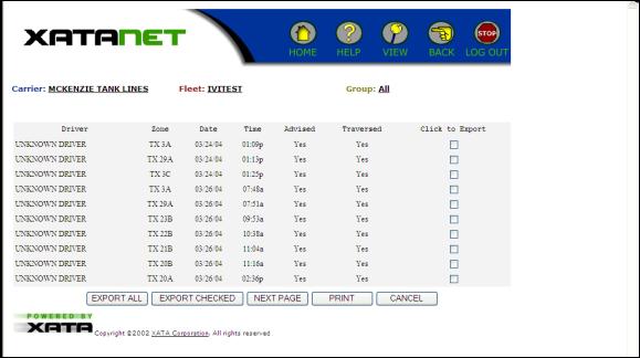
Figure D-6. Trucker Advisory Zone Summary Report Screen

Figure D-7. IVI Driver Profile Manager Screen
The IVI Driver Profile Manager screen (Figure D-7) allows the user to manage which systems have an active driver interface, on a per-vehicle or per-driver basis.

Figure D-8. Emergency Personnel Notification Manager Screen
The Emergency Personnel Notification Manager screen (Figure D-8) allows users to enter up to six email addresses, which will be the recipients of crash notifications.

Figure D-9. Major Lane Excursion Summary Screen
The Major Lane Excursion Summary screen (Figure D-9) allows the user to specify a particular driver, vehicle, and date range for lane excursion occurrences. The screen shown in Figure D-10 illustrates one such report. Detailed data can be exported as an Excel file and emailed to the user.

Figure D-10. Lane Excursion Summary Report Screen

Figure D-11. Operations Summary Screen
The Operations Summary screen (Figure D-11) allows the user to specify a particular driver and date range for general data about the vehicle location and systems status, per the data table in Section II. The screen shown in Figure D-12 illustrates one such report. Detailed data can be exported as an Excel file and emailed to the user.

Figure D-12. Operations Summary Report

Figure D-13. SafeTRAC? Manager Screen
The SafeTRAC? Manager screen (Figure D-13) allows the user to adjust the parameters for SafeTRAC? issuing alarms and collecting data for lane excursions. Values can be entered into the boxes as needed by the evaluator.
For Curvature Bin Average Weight, the choices are 1, 2, 4, and 8.
For Lane Excursion (LEX) Valid Confidence Delay Time, the user may enter a range from 0 to 9 seconds.
For the 5 Hz Lateral Offset Combination Rule, the user can choose between "peak" and "average."

Figure D-14. SmartCell Encounter Manager Screen
The SmartCell Encounter Manager screen (Figure D-14) allows the user to modify existing TAZ or create new zones by entering data in the boxes shown.

Figure D-15. SmartCell Notification Manager Screen
The SmartCell Notification Manager screen (Figure D-15) allows the user to adjust the notification message provided to a driver when the vehicle enters a TAZ.
This section documents the installation of the equipment used for the FOT. The primary hardware components of the IVI equipment were:
VES Assembly
SafeTRAC?
Onvoy Antenna
Interconnect wiring
The VES Assembly provided the housing for crash sensors, the J1708 databus interface, and the information processing portion of the Onvoy system. The communications portion of the Onvoy system was integrated with the antenna mounted on the roof of the cab.
VES Assembly
The VES Assembly is an enclosure installed in the sleeper berth of the truck. It is located in the luggage compartment under the bunk, on the passenger side.
The VES Assembly was designed and replicated early in the project, so the components within the Assembly reflect the original project plan for ACN. The unit contains a tilt sensor (to detect rollover events) and an accelerometer (to detect longitudinal crashes), as well as equipment to communicate a crash notification via the Orbcomm satellite service in the event that cellular phone coverage was unavailable. These components were not used for the LDWS data collection.
Also in the VES Assembly is a unit which interfaces with SafeTRAC? and the vehicle?s J1708 data bus, which in turn feeds data to the Onvoy Interface to process and format the data for wireless upload. Data from the Eaton® VORAD® unit was available on the J1708 data bus.
These components are shown in Figure E-1. The installation location under the sleeper bunk is shown in Figure E-2. Cables for the VES Assembly are routed through a hole drilled into the sleeper berth.

Figure E-1. VES Assembly Internal Components

Figure E-2. VES Assembly Installation Location Under the Sleeper Bunk protein
Antenna
The Onvoy antenna/transceiver was mounted to an existing QUALCOMM antenna bracket. Two views of the mounting method are shown in Figures F-3 and F-4. Cables from the Onvoy transceiver were routed to the VES Assembly. (The QUALCOMM system was not a part of the IVI project.)

Figure E-3. Onvoy Antenna (right) shown next to QUALCOMM antenna (left)

Figure E-4. Alternate View of Antenna Mounting Method for Onvoy
SafeTRAC?
The SafeTRAC? is installed within apod which is attached directly on the dash using inserts and screws (Figure E-5).

Figure E-5. SafeTRAC? Pod Mounting Position
The pod is mounted over a hole drilled through the dash for all the cable connections. The SafeTRAC? system requires an RS 232, left and right directional signal inputs, +12 volt ignition power, and ground connections. The harness for 12V ignition power and ground is routed through the hole under the SafeTRAC? pod and to the terminal block on the passenger side of the cab. The terminal block is shown in Figure E-6. The RS 232 harness and the directional cables are fed through a hole in the passenger side floorboard. The RS 232 harness runs to the rear of the truck, into the luggage compartment, and is connected to the VES Assembly. The directional cables run to the firewall terminals located outside the cab on the driver?s side of the vehicle.

Figure E-6. Terminal Block
Harness Connections and Color Codes
SafeTRAC?
Status Cable Black ? left turn
White ? right turn
Black/White ? Brake
RS232 White TX
Red RX
Black Gnd
Green Gnd
Shield Gnd
Power/Ground 12 Volts IGN Black
Ground Black/White
VES Assembly
J1708 Clear (+) J1708
Black (?) J1708
Power/Ground 12 Volts Red
Ground Black
Windshield Wiper Park
Wire # 21F2.0 Red
The following information was provided to drivers in performing system check-out procedures.
To the driver:
Below is a set of maneuvers that we need you to take as part of our check-out of the SafeTRAC? system installed in your truck.
The system collects only 60 seconds of data at one time. Therefore, we want you to try to complete as much of each sequence as possible within 60 seconds. Please note what you could and could not complete.
Sequence 1:
Start Time 11:10 am
Start with truck in the center of the right (outer) lane.
1) Count to 10.
2) Steer to the right so that the front right tire is no more than 10 inches over the solid line and onto the shoulder. Hold the truck there, count to 3 and then return to the center of the lane.
3) Count to 10.
4) Steer to the right so that the front right tire is at least 18 inches onto the shoulder. Hold the truck there, count to 3 and then return to the center of the lane.
5) Count to 10.
6) Put your left turn signal on and change lanes.
End Time 11:11 am
DATA COMMENTS:
Got data for this excursion.
Small Right Excursion (~ 9") for 3 seconds
Return to center for ~10 seconds
Large Right Excursion (~ 51") for 8 seconds
Immediate signaled left lane change
Immediate signaled right lane change
Wait 1 ? 2 minutes
Sequence 2:
Start Time 11:14 am
Start with truck in the center of the right (outer) lane.
1) Count to 10.
2) Steer to the right until the right front tire is onto the shoulder by 12 to 18 inches. Hold the truck there, count to 3 and then return to the center of the lane.
3) Count to 10.
4) Steer to the right until the right front tire is at least 18 inches onto the shoulder. Hold the truck there, count to 3 and then return to the center of the lane.
5) Count to 10.
6) Make a lane change (right to left lane) without using your turn signal.
End time 11:15 am
DATA COMMENTS:
Got data for this excursion?
Large Right Excursion (~51") for 8 seconds
Wait 1 ? 2 minutes
Sequence 3:
Start Time 11:16 am
Start with truck in the center of the right (outer) lane.
1) Count to 10.
2) Steer to the left until the left front tire is over the dashed line by no more than10 inches. Hold the truck there, count to 3 and then return to the center of the lane.
3) Count to 10.
4) Steer to the right until the right front tire is onto the shoulder by 12 to 18 inches. Hold the truck there, count to 3 and then return to the center of the lane.
5) Count to 10.
6) Put your left turn signal on and change lanes (right to left lane).
End Time 11:17 am
DATA COMMENTS:
Got data for this excursion.
Large Left Lane Excursion (~ 25 ") for 5 seconds.
Return to center for ~12 seconds
Large Right Lane Excursion (~21 ") for 5 seconds. NO SAFETRAC? DRIFT ALERT
Return to center for ~10 seconds
Signaled Left Lane Change
Wait 1 ? 2 minutes
Sequence 4:
Start Time 11:18 am
Start with truck in the center of the right (outer) lane.
1) Count to 10.
2) Steer to the left until the left front tire is over the dashed line by no more than10 inches. Hold the truck there, count to 3 and then return to the center of the lane.
3) Count to 10.
4) Steer to the right until the right front tire is onto the shoulder by at least 18 inches. Hold the truck there, count to 3 and then return to the center of the lane.
5) Count to 10.
6) Make a lane change (right to left lane) without using your turn signal.
End Time 11:19 am
DATA COMMENTS:
Got data for this run.
Large Left Lane Excursion (~22") for 7 seconds.
Return to center for ~15 seconds.
Large Right lane excursion (~40") for 6 seconds
Return to center for 7 seconds
Unmingled Left Lane Change
Signaled Right Lane Change
Wait 1 ? 2 minutes
The next four sequences are "mirror images" of the last four. You will start in the left lane and steer the truck over the lines as described below.
Sequence 5:
Start Time 11:25 am
Start with truck in the center of the left (inner) lane.
1) Count to 10.
2) Steer to the left so that the front left tire is no more than 10 inches over the solid line and onto the shoulder. Hold the truck there, count to 3 and then return to the center of the lane.
3) Count to 10.
4) Steer to the left so that the front left tire is at least 18 inches onto the shoulder. Hold the truck there, count to 3 and then return to the center of the lane.
5) Count to 10.
6) Put your right turn signal on and change lanes.
End Time 11:26 am
DATA COMMENTS:
Got data for this run.
Large Left Lane Excursion (~24") for 6 seconds.
Return to center for ~10 seconds.
Large Left lane excursion (~42") for 9 seconds
Wait 1 ? 2 minutes
Sequence 6:
Start Time 11:27 am
Start with truck in the center of the left (inner) lane.
1) Count to 10.
2) Steer to the left until the left front tire is onto the shoulder by 12 to 18 inches. Hold the truck there, count to 3 and then return to the center of the lane.
3) Count to 10.
4) Steer to the left until the left front tire is at least 18 inches onto the shoulder. Hold the truck there, count to 3 and then return to the center of the lane.
5) Count to 10.
6) Make a lane change (left to right lane) without using your turn signal.
End Time 11:28 am
DATA COMMENTS:
Got data for this run.
Signaled Left Lane Change
Large Left Lane Excursion (~38") for 6 seconds.
Return to center for ~11 seconds.
Large Left lane excursion (~35") for 5 seconds
Wait 1 ? 2 minutes
Sequence 7:
Start Time 11:30 am
Start with truck in the center of the left (inner) lane.
1) Count to 10.
2) Steer to the right until the right front tire is over the dashed line by no more than 10 inches. Hold the truck there, count to 3 and then return to the center of the lane.
3) Count to 10.
4) Steer to the left until the left front tire is onto the shoulder by 12 to 18 inches. Hold the truck there, count to 3 and then return to the center of the lane.
5) Count to 10.
6) Put your right turn signal on and change lanes (left to right lane).
End Time 11:31 am
DATA COMMENTS:
Got data for this run.
Large Left Lane Excursion (~34") for 8 seconds.
Signaled Right Lane Change
Wait 1 ? 2 minutes
Did not complete; raining
Sequence 8:
Start with truck in the center of the left (inner) lane.
1) Count to 10.
2) Steer to the right until the left front tire is over the dashed line by no more than10 inches. Hold the truck there, count to 3 and then return to the center of the lane.
3) Count to 10.
4) Steer to the left until the left front tire is onto the shoulder by at least 18 inches. Hold the truck there, count to 3 and then return to the center of the lane.
5) Count to 10.
6) Make a lane change (left to right lane) without using your turn signal.
A driver brochure was developed to educate McKenzie drivers about the FOT and the equipment being evaluated. This brochure was distributed to drivers during Summer 2004. The text of the brochure follows:
You have been selected to participate in an evaluation of some new truck safety systems. This brochure will acquaint you with these systems and describe your role in the evaluation process.
Over the next several months, Mack Trucks, McKenzie Tank Lines, and the US Department of Transportation will conduct a field operational test (FOT) with up to 36 trucks to evaluate three new safety systems:
SafeTRAC? lane departure warning system
Automatic Crash Notification System (ACNS)
Trucker Safety Advisor (TSA)
The SafeTRAC? and TSA systems are designed to reduce the likelihood of crashes, but if a crash occurs, the ACNS will assist by notifying appropriate responders.
The FOT will help to evaluate the potential benefits of these technologies to you as a driver, to other drivers on the road, to the fleet operator, and to society in general. The goal is to improve highway safety.
The US Department of Transportation has hired Battelle, an independent, non-profit R& D company, to evaluate the benefits of these systems.
Your participation in this FOT will not affect your normal duties as a McKenzie truck driver-you will continue to make hauls just as you did before. During the FOT, some of the systems in your truck will be turned on or off at various times. This will be determined by Battelle, and you will be notified before anything changes. McKenzie staff will provide information and instructions to you on the kinds of warnings and messages that you may get from each of the systems.
The New Safety Systems on My Truck
SafeTRAC?
SafeTRAC?, a lane departure warning system, is the main system that is being evaluated. SafeTRAC? uses a miniature camera looking at the road ahead to measure your vehicle's position in the lane. If you begin to drift out of your lane, or if you try to change lanes without using either your turn signals or your brakes, the SafeTRAC? system will sound an audible warning tone.
Automatic Crash Notification System (ACNS)
The ACNS detects when you have had a crash by monitoring your truck?s speed and tilt, and major impacts on the front of your truck. The ACNS sends an emergency notification signal through satellite communications directly to McKenzie fleet management. The ACNS will be invisible to you-it does not make any audible noises or give you any messages.
Trucker Safety Advisor (TSA)
The Trucker Safety Advisor provides you with in-cab advisories as you approach areas of the highway that historically have been hazardous or that are suspected to be hazardous. The advisories are intended to provide you with enough forewarning to allow you to be aware of and prepared for the situation ahead. This is like displaying a road sign on your dashboard. This is expected to result in fewer surprises to you and thus, safer driving. The system consists of a Global Positioning System (GPS) receiver, a computer, and a database of hazardous locations. The GPS keeps track of your truck?s location and lets you know when you are approaching a known or suspected hazardous location. A message is displayed on a screen in the dashboard, accompanied by an audible tone to alert you.
For the FOT, this system will be activated on only a few trucks, beginning in late 2004. For most trucks, there will be no messages displayed at any time during the FOT. You will be notified if your truck?s TSA will be activated.
My Role as a Driver
As a driver of one of the test vehicles, you have a very important role in the Field Operational Test. Battelle will seek your input through interviews and surveys to understand how these technologies work for you.
Your name and the information you provide will be treated as confidential, and Battelle will not share them with your employer or others. Battelle?s reports will present general statistics and findings from this evaluation, and no names will be released.
How the FOT Will Work
The testing will begin with the ACNS operational. During this ?baseline? period, the test system will record data to establish a normal operating pattern for your truck. The baseline period will last between one and four months, and may have started several months ago. When it is over, the SafeTRAC? system will be turned on automatically and you will receive a Qualcomm message telling you that it has been done. The test period for your truck may be different than the test period for another truck. Test periods for all trucks begin sometime between August 1 and November 1, 2004.
The ACNS will be operational throughout the baseline and test periods. Some trucks will have the TSA system activated, and those drivers will be notified when that occurs.
Vorad Collision Warning System
Your truck is also equipped with a Vorad collision warning system, which will be turned on at all times during the baseline and test periods. However, this FOT is not intended to evaluate the Vorad.
What Is Expected From Me As A Driver?
Your opinions and observations about these systems are very important inputs to this evaluation. During the FOT, you will be asked to participate in interviews and complete questionnaires. Most of the questions will focus on the SafeTRAC? system-or TSA, if it is activated-but you may be asked similar questions about the Vorad system for comparison purposes.
1) Initial interview
Shortly after the SafeTRAC? system is activated on your truck, you will be asked to participate in an initial telephone interview with the independent evaluator, Battelle. The interview will involve questions concerning your initial impressions of these types of systems and your expectations or initial understanding of how they will affect your driving.
You will receive a Qualcomm message from the fleet operator asking you to call a toll-free number within a couple of days.
When you call the 800 number, you will be asked to indicate your truck?s ID and your driver ID number.
We will interview you over the phone. We expect that the interview will take about 20 minutes.
If you are a member of a team, we will need input from both drivers.
2) Monthly Questionnaires
After the initial interview you will be asked to complete short questionnaires sent to you through your Qualcomm system. This will occur at least two times; but no more than once per month. The questionnaire will include about ten questions pertaining to your driving experiences. You will be able to answer the questions through the Qualcomm messaging system; we expect the whole process to take about 5 minutes.
3) Completion Interview
When the Field Operational Test program is completed, we will conduct a final interview that will be similar to the initial interview. Like the initial interview, this completion interview will probably be conducted by telephone but may be conducted in person.
4) Exit Interview
We hope you will be able to participate in this FOT for the entire period (it ends on January 31, 2005). However, if you leave McKenzie before the test is over, or if you are assigned to a different truck, please notify us so that we can arrange to have a final telephone interview with you.
Why is My Opinion Important?
These systems are for you, and you are the most important source of information on how well they work. Your perspective on the benefits and drawbacks of these technologies will help to improve safety for truck drivers and for all drivers. We encourage you to provide your honest opinions and share your experience with these technologies. Again, your name and the information you provide will be treated as confidential, and Battelle will not share them with your employer or others.
The participation of all drivers in this test is very important, and we appreciate your help in making this evaluation a success.
If you have any questions at any time about the evaluation, please call Battelle or the Federal Motor Carrier Safety Administration (FMCSA).
ACN Automatic Crash Notification
FOT Field Operational Test
FMCSA Federal Motor Carrier Safety Administration
GPS Global Positioning System
IVI Intelligent Vehicle Initiative
LDWS Lane Departure Warning System
LEX Lane Excursion
TAZ Trucker Advisory Zones
TSA Trucker Safety Advisory or Trucker Safety Advisor (product)
USDOT US Department of Transportation
VIP Vehicle Information Profiler
VMT Vehicle Miles Traveled
VORAD Vehicle On-board Radar


|
 Print
Print