Special Report:
Accessible Public Rights-of-Way
Planning and Design for Alterations
PDF version
August 2007
This report and its recommendations are the work of a subcommittee of the Public Rights-of-Way Access Advisory Committee (PROWAAC) and are intended to provide technical assistance only. The report is not a rule and has no legal effect; it has not been endorsed by the U.S. Access Board, the Department of Justice, or the Federal Highway Administration of the Department of Transportation.
Public Rights-of-Way Access Advisory Committee (PROWAAC)
Subcommittee on Technical Assistance
Jerry Markesino, PROWAAC Chair, Portland, OR
Janet Barlow, TAM Subcommittee Chair, Atlanta, GA
Document Produced by Otak, Inc. |
|
 |
Table of Contents
ABBREVIATIONS
AASHTO—American Association of State Highway and Transportation Officials
ADA—Americans with Disabilities Act
ADAAG—ADA Accessibility Guidelines
APS—Accessible Pedestrian Signal(s)
APWA—American Public Works Association
CIP—Capital Improvement Program
DOJ/USDOJ—United States Department of Justice
DOT/USDOT—United States Department of Transportation
DWS—Detectable Warning Surfaces
FHWA—Federal Highway Administration
ITE—Institute of Transportation Engineers
MUTCD—Manual on Uniform Traffic Control Devices
NCHRP—National Cooperative Highway Research Program
PAR—Pedestrian Access Route
PBIC – Pedestrian and Bicycle Information Center (http://www.pedbikeinfo.org), an FHWA grantee/
transportation institute at the University of North Carolina. The PBIC is made up of the core staff of
professionals at the UNC Highway Safety Research Center, including engineers and planners who are
knowledgeable on walking and bicycling issues.
PROWAAC—Public Rights-of-Way Access Advisory Committee
PROWAG—Draft Proposed Right-of-Way Accessibility Guidelines
STIP—State Transportation Improvement Program
STP—Surface Transportation Program
TIP—Transportation Improvement Program
Title II—ADA implementing regulation for title II, as printed in the Federal Register (7/26/91).
The Department of Justice’s regulation implementing Title II, Subtitle A, of the ADA, which prohibits
discrimination on the basis of disability in all services, programs, and activities provided to the public by
State and local governments, except public transportation services (which are covered by Subtitle B, the DOT
regulation).
CHAPTER 1: INTRODUCTION
by Mary O'Connor, Transportation General Manager, City of Scottsdale, AZ; Barbara McMillen, Pedestrian Accessibility Specialist
The Public Right-of-Way
The public right-of-way is a complex space serving multiple users and functions. The sidewalk and street crossing network is the basic unit of pedestrian mobility and its surfaces support all of us—from children to elders—in both pleasant and inclement weather. Private, transit, and commercial vehicles vie with pedestrians for right-of-way width. All modes of travel, including motor vehicles, rail transit, and foot traffic share time and space at intersections. Power companies maintain above-ground and below-ground transmission lines; municipalities own and operate surface streets and sidewalks; and utility companies and public agencies oversee below-grade sewers, water mains, gas mains, and data and telecommunication networks. The public right-of-way in large cities may include both air rights and underground circulation routes used by pedestrians. Adjacent to the right-of-way, private property owners construct, maintain, and operate buildings, entries, driveways, sidewalk vaults, basements, and other improvements and expect usable connections to and from public sidewalks and streets.
Over the last decade, roadway design principles have been expanded to include pedestrian travel accommodations that are increasingly being sought in residential neighborhoods and commercial centers in suburban and urban development. Designs are now expected to reflect equity and context and to balance pedestrian and vehicular use. The design pedestrian is now understood to be not an individual but a range of users—children, elders, people pushing or pulling strollers and delivery carts, using a wheelchair or scooter, or traveling with a long/white cane or a service animal—for all of whom the roadway and pedestrian environment must function effectively. Many of right-of-way users are people whose independent mobility requires pedestrian travel; they are best served by a network of accessible facilities that can provide efficient and safe route choices for a wide range of trip types.
| |
 |
| |
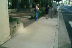
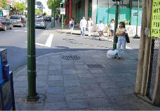
Photograph of a sidewalk widened to go around an obstruction. |
Our extensive system of existing roadways is constantly being improved. The vast majority of work in the public right-of-way environment is reconstruction, alteration work, not new construction. The bulk of public works funds are used to maintain and to make changes in those existing environments, rather than to create new facilities. Each altered element must be accessible to and usable by people who have disabilities, to the maximum extent feasible. Integrating accessible features in planned alterations projects requires an understanding of both regulatory and usability concepts. This technical assistance publication has been developed to provide guidance in the planning and design of pedestrian improvements constructed as part of an alteration project. Its text, illustrations, and case studies aim to expand the reader's body of knowledge in accessible right-of-way design.
Accessibility Regulations
The Americans with Disabilities Act (ADA) of 1990 is a civil rights statute that prohibits discrimination against people with disabilities. ADA implementing regulations for Title II prohibit discrimination in the provision of services, programs, and activities by state and local governments. Designing and constructing pedestrian facilities in the public right-of-way that are not usable by people with disabilities may constitute discrimination. Section 504 of the Rehabilitation Act of 1973 (504) includes similar prohibitions in the conduct of federally-funded programs.
Thus, the accessibility objective in a new project is to design and build facilities that are ‘readily accessible to and usable by' people with disabilities. Compliance is measured against the referenced standards. From the ADA Title II implementing regulation:
(c) Accessibility standards. Design, construction, or alteration of facilities in conformance with [UFAS] or [ADAAG] shall be deemed to comply with the requirements of this section with respect to those
facilities …
 |
|
The PROWAAC Committee at its January 2001 presentation of its recommendations for new PROW guidelines, “Building a True Community.” |
|
Furthermore, equivalent facilitation—achieving accessibility's objectives by other means than are described in the standard—is recognized:
… Departures from particular requirements of either standard by the use of other methods shall be permitted when it is clearly evident that equivalent access to the facility or part of the facility is thereby provided.
However, ADA standards for new construction and alterations promulgated (as guidelines) by the U.S. Access Board and adopted by the U.S. Department of Justice (DOJ) in 1991 were principally developed for buildings and site work and are not easily applicable to sidewalks, street crossings, and related pedestrian facilities in the public right-of-way. Similarly, Section 504 standards (UFAS or ADAAG for USDOT, depending on the agency) did not offer guidance appropriate for rights-of-way construction. The need to address rights-of-way accessibility in a more specific way is apparent from the difficulties practitioners and agencies have in applying ADAAG to this very different environment.
Progress Towards Accessibility Standards for New Construction and Alterations in the Public Right-of-Way
The Access Board is the Federal government's specialist in accessible design. Under the ADA, the Board is responsible for developing the minimum accessibility guidelines needed to measure compliance with ADA obligations when new construction and alterations projects are planned and engineered.
In 1999, the Access Board started the rulemaking process for accessible pedestrian facilities in public rights-of-way by convening a Federal advisory committee of key stakeholders to develop recommendations that could supplement or replace the current standard. The Public Rights-of-Way Access Advisory Committee (PROWAAC) completed its initial work in 2000 and published its recommendations for new guidelines in a report, Building a True Community, which was presented at the 2001 Transportation Research Board Annual Meeting.
Resource: PROWAAC Report at:
http://www.access-board.gov/prowac/commrept/index.htm.
On June 17, 2002, the Access Board issued a Notice of Availability of Draft Public Rights-of-Way Accessibility Guidelines (PROWAG) based on the PROWAAC report. Comments from consumers and design professionals led to the issuance of a second draft on November 23, 2005. A Notice of Proposed Rulemaking (NPRM) will follow seeking public comment prior to publication of a final rule.
Resource: November 23, 2005 draft PROWAG at:
http://www.access-board.gov/prowac/draft.htm.
The DOJ and U.S. Department of Transportation (DOT) are authorized by law to adopt standards consistent with the Access Board's guidelines for use in enforcing the ADA. The DOT has a similar authority under its Rehabilitation Act/504 regulation. The DOJ reviews 504 regulations issued by Federal agencies. When standards consistent with the final PROWAG guidelines are adopted by the DOJ, they will become the new minimum design standards under the ADA for both new construction and alterations of pedestrian facilities in the public right-of-way. The DOT has already indicated its intent to adopt the PROWAG, when completed, into its 504 standard.
In the interim, jurisdictions must continue to design and construct new and altered pedestrian facilities that are accessible to and usable by people with disabilities. The 2005 draft PROWAG has been identified by DOT as the current best practice in accessible pedestrian design under the Federal Highway Administration's Federal-aid (504) regulation.
Resource: FHWA Memorandum of January 2006 at:
http://www.fhwa.dot.gov/environment/bikeped/prwaa.htm .
 |
|
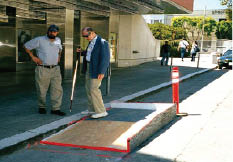 |
San Francisco uses plywood curb ramps with edge protection for temporary sidewalk detours. Here PROWAAC member Ken Stewart of CCLVI (with white cane) tests a model while Lukas Franck of The Seeing Eye looks on. |
Following completion of Building a True Community, the Access Board asked PROWAAC to develop guidance and recommendations focused on achieving accessibility in alteration projects within the public right-of-way. This advisory, Special Report: Accessible Public Rights-of-Way—Planning and Designing for Alterations, compiles the recommendations of a subcommittee of PROWAAC that worked to develop and highlight model rights-of-way design alternatives, design processes for making alterations, design solutions to specific problems, and case studies demonstrating examples of accessible design practices from across the country.
Alterations
The focus of this report is on improvement projects in the public right-of-way that are classified as alterations under the ADA.
Alterations are discretionary changes, which the agency chooses to fund, to existing facilities within an already-developed right-of-way where the work affects, or could affect, the usability of that facility. ADA Title II implementing regulations require that each part of a facility altered by, on behalf of, or for the use of a public entity after January 26, 1992, be designed and constructed so that the altered parts are readily accessible to and usable by individuals with disabilities to the maximum extent feasible. While the following quote is from the ADA Title III regulation, it is a useful explanation of alteration and existing facilities.
b) Alteration. For the purposes of this part, an alteration is a change to a […] facility that affects or could affect the usability of the building or facility or any part thereof.
(1) Alterations include, but are not limited to, remodeling, renovation, rehabilitation, reconstruction, historic restoration, changes or rearrangement in structural parts or elements, and changes or rearrangement in the plan configuration of walls and full-height partitions. Normal maintenance, reroofing, painting or wallpapering, asbestos removal, or changes to mechanical and electrical systems are not alterations unless they affect the usability of the building or facility.
(2) If existing elements, spaces, or common areas are altered, then each such altered element, space, or area shall comply with the applicable provisions of appendix A to this part.
(c) To the maximum extent feasible. The phrase “to the maximum extent feasible,'' as used in this section, applies to the occasional case where the nature of an existing facility makes it virtually impossible to comply fully with applicable accessibility standards through a planned alteration. In these circumstances, the alteration shall provide the maximum physical accessibility feasible. Any altered features of the facility that can be made accessible shall be made accessible. If providing accessibility in conformance with this section to individuals with certain disabilities (e.g., those who use wheelchairs) would not be feasible, the facility shall be made accessible to persons with other types of disabilities (e.g., those who use crutches, those who have impaired vision or hearing, or those who have other impairments).
All state and local government entities are covered by this requirement. Regardless of whether state or local governments directly manage or delegate the development of facilities in the public right-of-way to the private sector, the same obligations apply.
Federal-aid facilities covered by 504 regulations follow a somewhat different approach, relating the scope of required accessibility improvements in an alteration to the scope of the overall project. When PROWAG is final, it is expected that FHWA Federal-aid regulations will be changed to reference the new document.
The Civil Rights Restoration Act of 1987 clarified that all programs and activities of Federal-aid recipients, subrecipients, and contractors are covered by 504 requirements. From a 1992 FHWA memo:
The efforts to prevent discrimination must address, but not be limited to, a program's impacts, access, benefits, participation, treatment, services, contracting opportunities, training opportunities, investigations of complaints, allocations of funds, prioritization of projects, and the functions of right-of-way, research, planning, and design.
Existing Facilities
Requirements for existing facilities and programs are stipulated in the DOJ ADA Title II regulation and the DOT/FHWA section 504 regulation. They apply a separate obligation for ‘program access' to existing facilities not otherwise being altered. From DOJ's ADA Title II technical assistance manual:
The Title II regulations impose a more generalized standard with respect to facilities covered by the ADA that were in existence in January 1992. Rather than applying the accessibility requirements to “[e]ach facility” that is covered (28 C.F.R. 35.151(a)), the regulations provide that a “public entity shall operate each service, program, or activity, so that the service, program, or activity, when viewed in its entirety, is readily accessible to and usable by individuals with disabilities.” 28 C.F.R. 35.150(a) (emphasis added). In addition, the regulations further provide that, even under this “entirety” approach, a public entity is not required “to take any action that it can demonstrate would result in * * * undue financial and administrative burdens.” 28 C.F.R. 35.150(a)(3).
The regulation governing existing facilities also provides that any “structural changes to facilities” necessary to comply with title II were to be made in accordance with a transition plan. 28 C.F.R. 35.150(d)(1). In particular, the regulation provides that such a “transition plan shall include a schedule for providing curb ramps” on “walkways” controlled by the public entity, “giving priority to walkways serving entities covered by the Act, including State and local government offices and facilities, transportation, places of public accommodation, and employers, followed by walkways serving other areas.” 28 C.F.R. 35.151(d)(2).
In assessing and addressing their responsibilities for existing facilities, many jurisdictions have relied heavily on two helpful tools—the self-evaluation and the transition plan. These tools were initially required under both 504 and ADA Title II regulations. Many jurisdictions have continued to use these tools to plan for addressing accessibility issues, assessing progress, and managing changing circumstances. In addition, DOT's 504 regulation requires that jurisdictions establish a system for periodically reviewing and updating the self-evaluation that forms the basis for the Federal-aid transition plan.
| |
 |
| |
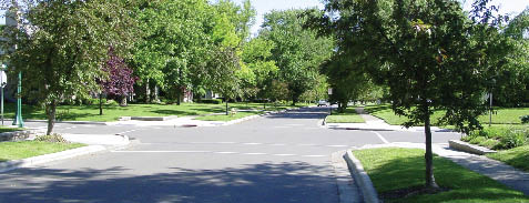
An urban intersection with paired perpendicular curb ramps, each with a 2-foot strip of detectable warnings at the toe. The flares have been shortened so that the ramps will both fit on the corner (flares are not a part of the pedestrian access route.)
|
A transition plan can provide decision-makers with an efficient tool for complying with section 504 and ADA requirements and holds information that often is not available in other planning documents. An updated transition plan will identify and locate elements and features that need to be added or altered, processes for determining accessibility priorities, and information that can be used in assessing the ‘undue burden' cost limitation in existing facilities. Cost is not a determinant in new construction and alterations.
While many methods may be utilized to achieve program access in existing facilities, ensuring usability in an already-developed pedestrian circulation system (a program) is likely to require remedial construction. In some cases, a new construction or alterations project will give rise to a program access obligation, as, for example, when a bus stop sign is placed in a hitherto-undeveloped environment. The presence of an existing bus stop that is not yet served by the pedestrian facilities needed to make it accessible—a pad for the deployment of a bus lift, a sidewalk for access to the stop—is a clear indicator of program access improvements that may need to be constructed for full use of the transportation system. It makes good economic and civil rights sense to look broadly at both responsibilities when new work is being planned and engineered.
Resources: DOJ's ADA title II regulation at:
http://www.ada.gov/reg2.html;
and a technical assistance manual at:
http://www.ada.gov/taman2.html;
DOJ's ‘Best Practices Toolkit for State and Local Governments' at:
http://www.ada.gov/pcatoolkit/toolkitmain.htm;
FHWA 504 regulation at:
http://www.fta.dot.gov/civilrights/ada/civil_rights_3907.html;
DOT planning documents at:
http://www.planning.dot.gov/documents/BriefingBook/BBook.htm;
DOT technical assistance at:
http://www.fhwa.dot.gov/civilrights/ada_memo_clarificationa.htm;
DOT memo on the Civil Rights Restoration Act at:
http://www.fhwa.dot.gov/legsregs/directives/notices/n4720-6.htm.
The following chapters provide an overview of alterations projects from a regulatory and practical perspective. We hope it will help you implement accessible and usable pedestrian facilities under the most stringent of conditions—within the constraints of existing developed streetscapes. We include useful information on the planning and pre-design process for public right-of-way alteration projects; engineering drawings illustrating typical barriers in a range of roadway conditions; case studies of real-world solutions to access constraints; plans that demonstrate how accessible features can be incorporated into sidewalks of varying widths; model curb ramp examples; and resources from local, state, and Federal agencies.
This guidance has been drawn from expert practitioners across the U.S. and is focused entirely on improvement projects in the public right-of-way that can be considered alterations under the ADA. The design process for making accessibility improvements in alteration projects is not any different from the design process for traditional street modification projects. It involves the same use of standards, technical guidance, and product information that designers follow in every roadway design project. One key to success: recognition that ADA design standards are minima and maxima describing a range rather than design or engineering objectives. The running slope of a complying curb ramp may range between 0 and 1:12, but we suggest that designers set their calculations to fall within that range, not at its extreme, lest a construction or other anomaly affect compliance.
Case Study Examples
Throughout this Special Report are case study examples that illustrate alteration challenges and solutions applied to these challenges. Comments are provided to clarify the particular application and to provide the reader with background conditions to better understand the solution. Look for case study examples in a box similar to this one.
Case Study—Narrow Right-of-Way
-
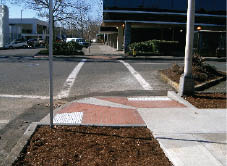
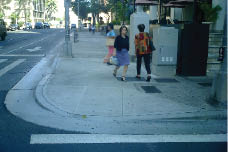
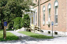
A midblock crossing and perpendicular curb ramp are aligned with an existing building entrance walkway. The walkway serves as the level landing for the curb ramp and the work was coordinated with the abutting property owner.
- Pedestrians can use the landing to bypass the descending ramp and its flares if they are continuing along the sidewalk.
- The midblock crossing has a pedestrian signal with a call button and an APS with a locator tone.
- Still needed: detectable warnings at the street edge.
|
Case Study—Narrow Right-of-Way
- The roadway travel lane was narrowed to add width to the pedestrian sidewalk and to accommodate the relocated parking meters.
- At the corner, a curb extension (bulb-out) into the parking lane provides the necessary space for a curb ramp and landing.
- The curb radius was omitted at this non-turning corner.
- Still needed: detectable warnings at the street edge.
|
Case Study—Downtown Redevelopment
| |
|
|
 |
| |
|
|
|
| |
The before photo (above) is a downtown streetscape in Pottstown, PA that was the subject of an improvement project to invigorate downtown retail, add bike lanes, and increase parking. The after photos (left) show the changes: new angled parking, bike lanes and more visible markings. |
|
 |
- The project required other improvements that offered opportunities for increased access: re-striping, new controllers and vehicle and pedestrian signals (existing equipment did not meet new MUTCD standards), and new curb ramps where bulb-outs were added.
- New accessible parking spaces were located near intersections to take advantage of the curb ramp serving the crossing.
|
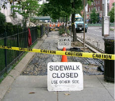
 Case Study—Work Zone Accessibility Case Study—Work Zone Accessibility
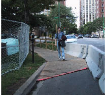
- The photograph shows a same-side temporary pedestrian route that bypasses construction on the sidewalk.
- Plywood surfacing is used where the route crosses grassy terrain; the joint is highlighted with contrasting paint. Still needed: a better bevel at the joint.
- The edge of the plywood walkway provides an adequate wayfinding cue on the opposite side (it provides good sound-on-cane information.) Chain link fencing is poor as a channelization enclosure, since it is not easy to follow with a cane and usually requires ‘feet' that narrow the walkway.
|
CHAPTER 2: ALTERATIONS
by Jerry Markesino, PE, Otak, Inc.; Michele Ohmes, APWA
| |
 |
| |
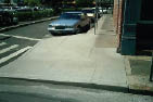
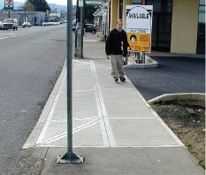
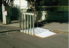
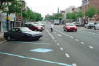
This urban alteration to replace a block of sidewalk and curbing is constrained by right-of-way width, existing adjacent entrances, and the presence of a bus stop requiring a deployment area for a lift. At pedestrian crossings, the project must incorporate (or improve, as feasible) curb ramps. Note that print signage and plastic tape do not adequately protect the excavation—a detectable barrier is needed. Consider also a proximity-activated ‘audible sign' to give notice of the blocked sidewalk. These are available from several barricade manufacturers and can be locally recorded with a specific detour message.
|
Alteration projects in the public right-of-way present particular challenges because of the limits of width and grade already established in the existing developed environment. Doorways cannot be readily changed because the threshold elevation is linked to the finished floor elevation of the building, which is not part of the project scope. Underground vaults and utility services cannot easily be relocated. Mature trees cannot be moved and will die if adjacent grade is raised or lowered or root growth is affected by construction. A railroad overpass pinches a narrow roadway and leaves no space for sidewalks to be added. Accessibility features that can easily be provided in the course of a new construction project are more difficult to incorporate in alterations because of such physical constraints.
An alteration project may differ from a new construction project because of existing development, which limits available space and has fixed access points and elevations that must be addressed. Where existing constraints in an alteration project prevent the full implementation of accessibility objectives (whether measured by appropriate standards, where they exist, or by usability if they do not), the ADA and 504 regulations provide a degree of flexibility to designers and agencies. From the ADA Title II regulation:
35.151 New construction and alterations. (b) Alteration. Each facility or part of a facility altered by, on behalf of, or for the use of a public entity in a manner that affects or could affect the usability of the facility or part of the facility shall, to the maximum extent feasible, be altered in such manner that the altered portion of the facility is readily accessible to and usable by individuals with disabilities, if the alteration was commenced after January 26, 1992.
Here is the text on infeasibility in alterations projects from the ADA Standards (Section 4.1.6 (j) of Appendix A, 28 CFR Part 36):
(j) EXCEPTION: In alteration work, if compliance with 4.1.6 is technically infeasible, the alteration shall provide accessibility to the maximum extent feasible. Any elements or features of the building or facility that are being altered and can be made accessible shall be made accessible within the scope of the alteration.
Technically Infeasible. Means, with respect to an alteration of a building or a facility, that it has little likelihood of being accomplished because existing structural conditions would require removing or altering a load-bearing member which is an essential part of the structural frame; or because other existing physical or site constraints prohibit modification or addition of elements, spaces, or features which are in full and strict compliance with the minimum requirements for
Note that cost is not a trigger of infeasibility in alterations.
Since alterations under the ADA are required to meet new construction criteria to the maximum extent feasible, extensive reconstruction work can and should approach the accessibility required of new construction. For example, a project that calls for the removal of pavement and sidewalks to subgrade, followed by the installation of new walks and pavement, is an alteration whose broad scope offers significant opportunity to incorporate the full range of accessible features. On the other hand, the installation of a single curb ramp at an existing intersection is an alteration with limited scope for correcting adjacent inaccessible conditions.
Terminology
In the transportation industry, construction work may be classified as new construction—the installation of improvements where none currently exist—or reconstruction. State agencies often use ‘4R' terminology: reconstruction, rehabilitation, restoration and resurfacing. Local agencies may refer to reconstruction work as modification, renovation, upgrading, rebuilding, and modernization. Federal highway agency nomenclature relies on new construction, reconstruction, and ‘3R (resurfacing, rehabilitation, and restoration of pavements)'. Whatever term is used, the removal of some existing improvements and installation of replacement improvements constitutes an alteration under the ADA.
The reconstruction of a roadway, the upgrading of a sidewalk, or the installation of other elements are alterations when they affect usability, temporarily or permanently, for pedestrians or vehicles. Transportation agencies may consider resurfacing a roadway a maintenance item, for ADA purposes it has been considered an alteration with respect to the special Title II obligation at 35.151(e) to install curb ramps.
Resources: Yerusalim at:
http://www.access-board.gov/prowac/yerusalim.htm
DOJ ‘Common Problems' at:
http://www.ada.gov/comprob.htm
Project Civic Access Agreements at:
http://www.ada.gov/civicac.htm
Memorandum Clarifying FHWA Oversight Role in Accessibility at:
http://www.fhwa.dot.gov/civilrights/ada_memo_clarificationa.htm
FHWA Questions and Answers About ADA and Section 504 at:
http://www.fhwa.dot.gov/civilrights/ada_qa.htm
FHWA Memorandum on Detectable Warning Requirements at:
http://www.fhwa.dot.gov/environment/bikeped/dwm.htm
Curb Ramps
Under the ADA, an alteration to a sidewalk or street will give rise to an additional obligation to include curb ramps in the scope of the project. From the Title II regulation:
35.151(e)(2) Curb Ramps. (1) Newly constructed or altered streets, roads, and highways must contain curb ramps or other sloped areas at any intersection having curbs or other barriers to entry from a street level pedestrian walkway. Newly constructed or altered street level pedestrian walkways must contain curb ramps or other sloped areas at intersections to streets, roads, or highways.
In addition, the Title II regulation requires that jurisdictions prepare and implement a curb ramp schedule for their existing facilities, subject to certain time and cost limits:
35.150(d)(2) Transition plan. If a public entity has responsibility or authority over streets, roads, or walkways, its transition plan shall include a schedule for providing curb ramps or other sloped areas where pedestrian walks cross curbs, giving priority to walkways serving entities covered by the Act, including State and local government offices and facilities, transportation, places of public accommodation, and employers, followed by walkways serving other areas.
| |
|
| |
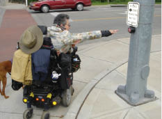
This new parallel curb ramp on a large-radius suburban corner curves down to the street and is otherwise usable, but the pedbutton isn't. Installed on a signal pole, it is out of horizontal reach range for this pedestrian. A better installation can be seen across the street, where a stub pole has been installed in a more usable location.
|
Project Physical Constraints
Since alteration projects are always constructed within an existing developed environment, there will always be existing facilities to deal with. Roadways, sidewalks, trees, utilities, adjacent private improvements, street lights, traffic signals, and a multitude of other facilities are already there. When one of the items is identified for reconstruction, it is likely that other facilities will be involved. This is simply the nature of this type of work.
Depending on the scope of the project, these existing facilities need to be considered in the project design. In some cases, desirable changes can be included with a small expansion in project scope and designed and built with little impact on the primary project. In other cases, removal of barriers to program access or correction of inaccessible adjacent construction should remain outside the scope of work.
Existing facilities can become physical constraints that impose a limit on the extent of any right-of-way improvement. When a new streetcar trackway is being planned, the preferred alignment may lie directly over a shallow steel water main. If the trackway is built over the water main, the electric powered train will discharge power to the ground and cause corrosion to the water pipe. After a few years of operation, the electrical discharge will destroy the water main. A decision must be made to either realign the trackway or rebuild the water main and protect it from being destroyed by the electrical discharge. In this case, the water main has become a physical constraint that imposes limitations on the streetcar project, perhaps requiring an expansion in the project scope of work.
| |
|
| |
Ooops! Where's the wheelchair accessible route? Much better coordination is needed at this urban bus shelter location. Even though the sidewalk width is generous, tree boxes crowd the shelter on either side and a fixed trash can on one side and the bus stop sign on the other complete the job—it looks good but isn't usable because there's no pedestrian access route or pad of sufficient size to deploy a bus lift. The bicycle chained to the sign is the last straw! Best fix: move the trash can and bus stop sign.
|
In another example, an additional travel lane is proposed in the project scope and existing street trees occupy the space needed for the travel lane. The trees are a physical constraint. However, the scope of the project requires a new travel lane. It is likely that the trees will need to be removed. In this case, the tree removal and new tree planting elsewhere becomes part of the scope of the project. Ensuring that pedestrian facilities are accessible is just as important as meeting roadway design and operational guidelines. Where existing physical constraints are encountered, the project design should deal with them and deal with them in ways that are commensurate with the overall undertaking. For example, sight distance obstructions that affect intersection safety are routinely removed in an intersection modification project. Likewise, physical constraints that affect sidewalk usability should also be handled as a routine design practice.
When existing physical conditions affect the feasibility of achieving full conformance with accessibility criteria in an alteration, the design engineer should determine, on an element-by-element basis, what degree of usability can reasonably be achieved within the scope of the planned project.
The challenge of dealing with project physical constraints in alteration projects has been recognized by the authors of accessibility standards for years. In 1992, in the development of proposed regulations, the Access Board identified a number of possible physical constraints that might bear on the feasibility of certain accessibility features, including:
- the existence of an underground structure, such as a utility vault, manhole, or sewer inlet at a street crossing that may preclude the installation of a new public sidewalk curb ramp in full compliance with provisions for new construction;
- the geometric design of existing roadways, bridges, or tunnels constrained by structural elements that, even when altered, may not accommodate a public sidewalk with adequate width for wheelchair users;
- differences in finished grade at curbside and elevations at existing building entrances at the back-of-sidewalk that may preclude compliance with cross slope provisions across the entire public sidewalk width;
- existing fixed equipment, such as fire hydrants or street lighting standards, located on a public sidewalk and connected to below-grade water, power, signal, and similar distribution systems that may prevent full compliance with public sidewalk curb ramp provisions if the equipment cannot be relocated in the course of the work;
- existing narrow public si dewalks or rights-of-way that might preclude the maintenance of a continuous passage free of gratings required for new subway construction; or
- the existence of an established landscaping feature, such as a large tree or grouping of trees that may preclude the provision of a parallel access aisle at a newly-established on-street parking space. Furthermore, a pre-existing commercial use of the public sidewalk, as for a sidewalk café, may also constitute a physical constraint if no other location for an accessible parking space is feasible within the scope of the alterations project.
Public agencies and designers need to be creative and flexible in developing solutions that promote accessible travel. Adjusting the geometrics in an existing system takes a greater degree of creativity, thought, and engineering know-how than when starting from scratch on a new project.
An understanding of accessibility criteria and rationale, skills enhanced from engineering study, and design experience with accessible facilities will enable practitioners to develop and deploy a toolbox of approaches appropriate to a wide range of project conditions. Designers should consider the entire right-of-way that is available as they work to balance facilities between vehicle, bicycle, and pedestrian use.
| |
|
| |
Plenty of street width is available for an imaginative solution to curb ramp installation at this small town intersection. Open culverts extend several feet from the curb at cross streets and are bridged with concrete ramps, open below for drainage, and handrails for edge protection. Beginning at the top of the curb almost 15 inches above road grade, these flying ramps both protect the culvert and provide access to the crosswalk. Edge protection is needed, however, and detectable warnings at the street edge.
|
Resources:
AASHTO: “A Policy on Geometric Design of Highways and Streets”, 2004;
“Guide for the Planning, Design, and Operation of Pedestrian Facilities”, 2004: bookstore at https://bookstore.transportation.org/;
FHWA: “Manual on Uniform Traffic Control Devices”, 2003 http://mutcd.fhwa.dot.gov
Desirable objectives in the public right-of-way include curb ramps that are flatter than a 1:12 slope; adjacent landings that are near-level; signal call buttons within easy reach ranges of a person who uses a wheelchair; equipment installations that accommodate the techniques of low-vision and white cane travel; and crossing information that is usable by all pedestrians. Armed with an understanding of the rationale behind accessibility provisions and guidance available in industry documents, the street design professional will be well-prepared for the planning and engineering of alteration projects that include usable pedestrian facilities.
Analyzing Accessibility Alternatives
When physical constraints limit the application of new construction criteria, several potential approaches may be analyzed before selecting the solution that will optimize accessibility. Here is a simple two-step process for making decisions on selecting accessibility alternatives.
[In general, ‘accessible' is used in this document to mean elements or facilities that comply with applicable standards—this is the definition in ADAAG—and ‘usable' to characterize elements or facilities that are not addressed in the standard, which represent equivalent facilitation, or that fall short of full compliance with scoping or technical provisions for new construction. Note that the ADA implementing regulations require new facilities to be both ‘accessible to' and ‘usable by' people with disabilities.]
| |
|
| |
This curb ramp retrofit combines a parallel and a perpendicular ramp to stay within running slope limits. Curbed edges provide useful non-visual wayfinding cues. California State provisions (this is in Sacramento) require the corduroy markings at the intermediate landing, but research shows that the truncated domes required at the toe of the ramp (ADAAG 4.7) would provide a significantly more detectable indicator of the upcoming street crossing.
|
First: Consider the use of work-around alternatives that do not affect usability by pedestrians who have disabilities. For example, where there is a problem placing a curb ramp in a preferred location, consider:
- using an alternate form of curb ramp (parallel, combination, or perpendicular);
- identifying an alternate location for the ramp;
- widening the crosswalk to include the curb ramp;
- borrowing space from the parking lane or the roadway;
- adjusting the horizontal and/or vertical roadway geometries;
- extending a curb ramp through the gutter-pan area;
- raising the roadway surface at the gutter;
- lowering the curb height;
- raising the crosswalk;
- adding a curb extension to ‘grab' needed (and often more level) space for pedestrian facilities at corners;
- shielding the sides of a ramp with signs, sidewalk furnishings, and setbacks to eliminate the need for space-intensive flared sides; or
- ramping a sidewalk down to an intermediate level landing.
Second: If an alternative does not meet project constraints, favor approaches that have lesser usability implications. For example:
- modify curb ramp flare space requirements (the flare is not part of the required pedestrian access route [PAR]) or use returned curbs;
- construct a single curb ramp that can do the work of two;
- shave millimeters from a landing or decimals from the running or cross slope of a ramp;
- use a short length of blended or warped sidewalk that can be replaced during a future improvement to connect to existing undisturbed facilities; or
- blend non-conforming pavements in segments that provide as much planarity as possible for the wheelbase of a mobility device (~760 mm x
1220 mm).
| |
|
| |
Driveway crossings with excessive cross slope are one of the most common problems in alterations projects. Here, an existing driveway apron has been reconstructed to provide a level pedestrian route across it that is narrower than the sidewalk it connects to but adequate for travel over a short distance. In more constrained rights-of-way or where driveway slopes are steeper, a more complex intervention will be needed. Usability can be optimized by ramping the sidewalk down to an intermediate level at the driveway crossing and accepting a lip between apron and roadway.
|
Note that manipulating scoping requirements (one ramp where two will not work, a lesser number of accessible on-street parking spaces where construction is constrained) may also provide needed flexibility in conditions of infeasibility. Equivalent facilitation, obtaining the prescribed ends in another way, is also permitted. For example:
- use of an existing corner curb ramp to serve as an added accessible parking space where sidewalk space is limited;
- use of a leading-pedestrian interval (LPI) or all-red signal to provide crossing opportunities where other timings are not feasible;
- use of a voice message where pedbuttons cannot be separated by the necessary ten feet; or
- use of audible signage where there is insufficient room for tactile text.
The design engineer who is well-versed in accessibility rationale will recognize that some features of accessibility have greater safety and usability effects than others. For example, a lip at the toe of a curb ramp is a significant barrier because users may be crossing at speed, the grade break may be obscured by ponding, and a sudden drop or stop can propel a pedestrian from his or her mobility device. In contrast, the slope or length of a flared side of a ramp is not part of the pedestrian access route, and thus a lack of compliance with the standards is of little significance to usability. A narrow walkway adjacent to an active travel lane requires tighter control of the cross-slope on the sidewalk and curb than does a separated sidewalk set back from the roadway. Level landing areas are critically important where turns must be made.
Project Scope
In the most basic terms, the project scope describes the purpose of the project. The physical constraints of any project are challenges that may make project engineering complex, excessively expensive, or difficult to build. These challenges may require additional funds, cause the scope of work to expand, or kill the project altogether. The scope of work defines a project by answering the questions of What, Why, Where, When, and How. It includes the purpose and justification for the project. It also includes the physical and/or contractual limits of the work. With respect to pedestrian accessibility, the scope of a project must also address the obligations set by ADA Title II and 504 implementing regulations.
The project scope should consider the jurisdiction's transition plan, if one has been prepared. If inaccessible or unusable facilities within the project area have been identified in the transition plan for correction in the future, it is likely that they can most easily be corrected within the scope of the proposed alteration project, as it will generally be more cost effective to correct a known barrier by including it in a planned alteration project rather than wait and fix the problem at a later date. The limitation of project scope or boundary to avoid a program access improvement could give rise to a complaint.
The scope of accessibility improvements should be related to and commensurate with the scope of the overall project, particularly with regard to roadway improvements. Each element that is altered as part of the project must be designed and constructed to be accessible to and usable by people with disabilities to the maximum extent that this is feasible. Failure to provide accessible alteration project improvements may require a public entity, including responsible individuals, to defend their decision-making in court.
How do you know when you've maximized accessibility?
In roadway design, there are many ways to solve a problem. The confidence that a designer has properly applied good engineering judgment in a specific case can only come when accessible design has been fully integrated into the engineer's toolbox.
Designer A develops one solution; engineer B another for the same problem. How can agencies determine which design solution should be used? The U.S. Access Board, the U.S. DOJ, and the U.S. DOT do not approve project designs (or police construction) to ensure that the ‘best' solution is chosen. If the using public believes that a more accessible result might have been achieved, designers may have to defend their decision-making in court. If reasonable care can be demonstrated, then accessible design carries no more risks for public agencies than the design of other roadway features. A few states have a regulatory agency that reviews the design and construction of pedestrian elements to ensure accessibility. They may also have the authority to approve deviations to any state accessibility standards. However, Federal or private litigants are not bound by state or local approvals and may challenge such a decision in a complaint to DOJ or FHWA or an action in court. The best guidance is to approach accessible design and construction with the same care and commitment as all agency initiatives and to document staff training, planning and design procedures, and decision-making processes.
Members of the PROWAAC make the following recommendations:
- Designers need to expand the depth of their analysis and think outside the box.
- Designers should seek assistance from people with disabilities in the community. Consider their opinions and recommendations. Get input, advice, and support from local advisory committees.
- Designers must recognize that the first solution to a problem will not often be the best. Look hard and wide for creative solutions.
- Keep track of everything considered. Document the analysis work, findings, and decisions. Save them in the permanent project record file.
- Select the solution that best balances the needs of all users: people who use wheelchairs, people who have vision impairments, and other pedestrians, young and old. Avoid solutions where roadway improvements are fully realized at the expense of pedestrian accessibility.
- Network with others. Consult with peers in other agencies and firms. Share ideas and solutions.
- Attend continuing education classes that focus on accessible design.
- Develop, adopt, and use a standard method of design review and approval.
- Be prepared to defend your decisions in a potentially adversarial situation.
The recommendations above provide no guarantee that a project design will not be challenged. There will always be someone with a second opinion or a better design solution. However, if the scope of the project is clearly defined, research is adequate, and the method of selecting the preferred alternative is clearly documented, the solution can be adequately defended. It is the designer's responsibility to develop the expertise needed to evaluate potential alternatives before confirming an engineering solution. Note that cost cannot be the basis for eliminating workable alternatives in a planned alteration (however, there is a cost defense related to program access improvements; see 28 CFR 35.150(a)(3) of the Title II regulation).
Project Approach
Engineering judgment is defined in industry literature as the evaluation of available pertinent information and the application of appropriate principles, standards, guidance, and practices for the purpose of deciding upon the applicability, design, operation, or installation of public improvements.
| |
|
| |
In this photo, ITE wayfinding workshop participants work in small groups to develop curb ramp location recommendations based upon intersection corner radius (see the ITE Journal, July 2004).
|
The exercise of engineering judgment directs all the skills of the professional toward the solution of an engineering problem. Accessible pedestrian design practices are only now beginning to develop within the transportation engineering field. Over time, it is expected that a full body of knowledge will be established as the profession takes responsibility for this new aspect of roadway design. Designers should seek out and use currently available resources to assist them in their design efforts. As with any new skill—and this is true for the individual designer as well as for the leadership of the profession—competency in accessible pedestrian design can be gained through education, training, and practice and then be integrated into the current professional skill set. It must be noted that engineering judgement on its own is not a defense against an accessibility complaint.
The design recommendations in this technical assistance manual can help engineers integrate accessible design into the toolbox that is used every day as engineering judgment. However, it is impossible to give guidance specific to every situation, since there are many variables in even the simplest of projects. Seldom will existing conditions be comparable between even two similar projects. It is the intent of this manual to provide an awareness of the rationale behind accessible design provisions, with specific application to alteration projects, and to suggest methods and techniques that will advance current understanding and practice. Particular emphasis has been given to the civil rights concepts that underlie the ADA implementing regulation.
Frequently-asked Questions
When the revised draft guidelines for accessibility in the public right-of-way were published by the Access Board on November 23, 2005, the preamble to the draft (discussion) contained a set of questions and answers intended to help clarify the relationship between the scope of a planned alteration project and related physical constraints. The questions/answers did not address program access requirements (the Access Board mandate is the development of guidelines that can be adopted as Federal standards for new construction and alterations; the Board has no responsibility for ADA provisions governing existing facilities not otherwise being altered).
The same questions are repeated below. The answers have been expanded by the PROWAAC Subcommittee to identify areas where program access requirements may arise, in an attempt to provide a more complete picture of agency and jurisdictional obligations under Title II of the ADA and section 504 of the Rehabilitation Act.
Curb Ramps
1. Question: A multi-block length of roadway is being resurfaced. Existing sidewalk corners have curb ramps, but some of them don't meet current specifications. Must the curb ramps be reconstructed as part of the resurfacing project?
Answer: Resurfacing is considered an alteration and compliant features must be installed to the extent that it is feasible to do so. This work is required by 35.151(e) of the Title II regulation, not by ADA standards for construction, and must be done at the same time as the resurfacing. Discussion: This requirement is analogous to the ‘path-of-travel' requirement for buildings and facilities under which additional work is occasioned by a planned alteration. Curb ramps are the only item of construction specifically required by this provision in Title II, and only as a consequence of an alteration to a roadway or pedestrian walkway. DOJ technical assistance describes resurfacing as an alteration. Kinney vs. Yerusalim, a Federal court decision binding on the Third District, took a similar view, holding that roadway resurfacing constituted an alteration that required the installation of curb ramps. If it is feasible (see the Introduction for the ADA discussion of ‘maximum extent feasible') to provide greater usability/compliance with curb ramp standards, that should be done.
2a. Question: New curb ramps are being installed in an existing sidewalk that is being widened and resurfaced as part of a downtown improvement program. On one corner, an existing underground utility vault is located in the best spot for a curb ramp. Must the utility vault be moved to ensure that the toe of the curb ramp falls within the marked crossing?
Answer: The scope of this project will determine the answer. If utilities are being moved for other reasons within the project scope or limits, it may be feasible to alter or relocate the vault. If planned project construction does not involve the vault, it may not be feasible to locate the curb ramp in as optimal a spot as new construction standards would require. If at some future time the intersection is reconstructed and the utility vault is modified or relocated, there may be an opportunity to locate the curb ramp in the ideal location. Discussion: There are many work-arounds for barriers in the public right-of-way. Consider widening the crosswalk markings to include the new curb ramp location, raising the crosswalk if roadway use permits, or installing an apex ramp as a last resort.
2b. Question: What if the curb ramp can be placed over the vault, but an access cover would have to be located on the curb ramp to do so?
| |
|
| |
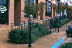
In this downtown improvement project in Auburn, AL, splitting the sidewalk allowed two objectives to be served: the upper level provides stepless access to shops and the lower level maintains access to the street. Landscaping, benches, and decorative wrought iron railings separate the two levels, which are connected by a ramp at midblock and blended to a common level at corners. The reconstruction borrowed street space to provide the sidewalk width needed for this imaginative solution in a daunting hilly streetscape.
|
Answer: An access cover on the curb ramp is not prohibited if it conforms to the surface requirements (stable, firm, slip resistant; no changes in level that exceed ADA standards, etc.) for the pedestrian route.
3. Question: One corner of an intersection is being altered by curb and gutter reconstruction to add a curb extension for traffic calming. Paired curb ramps will be installed as part of this project. The other three corners of the intersection are not being altered. Must curb ramps be provided (or improved) at the unaltered corners as part of this work?
Answer: No, although it may be more cost-effective to do so, since most corners should be fitted with curb ramps eventually. Curb ramps within the limits of the project at the altered corner are a required part of this work. Discussion: Existing corners without curb ramps are subject to section 504 and ADA Title II program access requirements; broadening the current project's scope of work to include them now may make good economic sense (unless future construction at other corners is already scheduled).
Sidewalks
4. Question: A project will be undertaken to connect a series of sidewalk segments near a school in support of a Federally-funded Safe-Routes-to-School (SR2S) program. Must the existing segments of sidewalk be modified if they do not meet width or cross slope provisions?
Answer: This is an alteration to an existing pedestrian circulation system and compliant features must be installed to the extent that it is feasible to do so within the scope of the project. Discussion: Since this is an area-wide project intended to provide student circulation routes between homes and school, and not just to link two separated segments of an existing walkway together, the project should be planned to include improvements to existing sidewalk segments that can feasibly be corrected within the scope of a sidewalk improvement project. Students with disabilities cannot be excluded from SR2S programs, which by their nature encourage walking and bicycling, and such programs carry their own program access responsibilities.
5. Question: A new sidewalk is being built along an existing road that contains many driveway access points. Must those driveways be modified if their cross slope exceeds 2%?
Answer: Yes, to the maximum extent feasible within the scope of the project. A new sidewalk, even when constructed as an alteration, must be designed to conform to accessibility standards to the extent that it is feasible to do so. Design guidance from the Access Board includes several driveway apron retrofit schemes (see Case Studies for details).
6. Question: A city is resurfacing a sidewalk along Main Street. The distance between the edge of the right-of-way and the existing roadway does not provide sufficient room for a four-foot-wide pedestrian access route. Does the municipality have to acquire more right-of-way from private property owners or narrow the roadway to provide a more conforming walkway?
Answer: No, accessibility guidelines do not require the municipality to obtain right-of-way or to narrow roadways in the limited scope of work of a sidewalk resurfacing project. However, if a municipality plans to narrow a roadway for traffic-calming purposes or acquire additional right-of-way as part of a downtown improvement project, it should plan the project in such a way as to accommodate new construction standards for sidewalk width. Note that ADA title II regulations will require the addition of curb ramps as part of this project, since it is an alteration to a sidewalk.
Signals
7. Question: Curb ramps are being installed at a signalized intersection as part of a roadway resurfacing project. Existing pedestrian push buttons (pedbuttons) are not accessible or placed in accessible locations. Must the pedbuttons be replaced with accessible models? Must accessible pedestrian signals be installed as part of this project?
Answer: The resurfacing alteration triggers the addition of curb ramps under the ADA Title II regulation. However, there is no requirement to expand the project scope to include other features of accessibility. On the other hand, pedbuttons which are too high, too far from the sidewalk, or are otherwise inaccessible will preclude use by residents with disabilities, raising program access issues. It may be more cost effective to fix them under the proposed project rather than make the improvements at some later date. Discussion: If the pedbuttons are being replaced as part of this project, the new equipment must meet accessibility standards for operating force, reach range, clear ground space, connection to the pedestrian route, etc. Existing pedbuttons may be relocated, subject to installation standards, but if they are of an inaccessible design, it may be a wiser course to replace them rather than risk a program access complaint.
8. Question: The pedestrian signals in a downtown corridor are being replaced with a new system combining WALK/DON'T WALK and count-down signals. Must Accessible Pedestrian Signals (APS) be included in the new system?
Answer: Yes. The installation of a new system is an alteration that must be accessible to and usable by people with disabilities to the maximum extent feasible. APS are widely available. Discussion: When a complete system is upgraded, controller and push button improvements that include APS capability can be added. Providing crossing information in usable formats should be included in the scope of work for a project of this size, complexity, and cost.
9. Question: Count-down signal displays are being added to some existing pedestrian signal heads at an intersection, but the software and signal controller are not being altered. Must APS be installed?
Answer: No, simply adding a display to the existing WALK/DON'T WALK signal would not involve the system changes needed to implement APS. Discussion: Note that program access provisions governing existing facilities may apply at any location, regardless of whether alterations are planned. If a resident with a disability requests APS information at a crossing, a jurisdiction must give consideration to installing them if necessary to provide accessibility. Maintaining a citizen request program, and acting on it, is one way that jurisdictions may satisfy program access requirements for existing facilities not otherwise being altered.
10. Question: An intersection is being signalized and will include APS. The installation of stub poles on the existing sidewalks to mount the new pedbuttons will disturb a limited area of sidewalk. Must curb ramps be installed if none existed?
Answer: No. The scope of this project is to install pedbuttons; it is not an alteration to the sidewalk or the street that would require the installation of curb ramps, as required by the ADA Title II regulation. Discussion: Curb ramps at this location would clearly be required under the section 504 and ADA Title II regulation and should have been included in the agency's transition plan. Their addition is an improvement that might well be scoped and scheduled as a part of this project.
11. Question: The push button on an existing pedestrian signal is being replaced with a sturdier model. Must APS be installed?
Answer: No, but the new push button must conform to applicable accessibility criteria (location, height, operating force limits). Discussion: Modern APS devices are usually integrated into the pedbutton. If every pedbutton at a corner is being replaced as part of this project and controller changes would not be required to support APS, it would be a wise use of public funds to consider APS installation, since a program access need can be anticipated to exist at most locations where pedestrian signals are provided.
12. Question: An intersection with existing sidewalks and pedestrian signals is being widened to include a right-turn lane. Must APS be installed as a consequence of the widening?
Answer: No, installing APS is not within the scope of this project. New pedestrian push buttons installed in the course of the work must meet applicable requirements (or existing ones may be re-installed; see Question 7). However, since this project is an alteration to the street and sidewalk, curb ramps must be installed or improved to the maximum extent feasible.
General
13. Question: The local public transit agency has designated a bus stop by placing a sign in the ground along a roadway that has no sidewalk. Must a concrete or another improved surface be provided in the course of the work?
Answer: No, the placement of a bus stop sign alone does not require other site improvements. However, the designation of the bus stop places future program access responsibilities on the jurisdiction, which must ensure system usability by residents who have disabilities. Discussion: While program access obligations may arise out of an expressed individual need for accommodation at a specific location, required transit system usability is dependent on having accessible bus stops where people want to go. In urban areas, jurisdictions should not wait for a resident request to improve a bus stop. In rural and suburban areas, a prompt response to the request of a passenger with a disability for accommodation may be sufficient. Residents who are not able to use a public transit system because of bus stop inaccessibility may be eligible for paratransit, but it is often more cost effective to improve the accessibility of bus stops instead. The Title II regulation requires structural improvements for program access to conform to alterations standards.
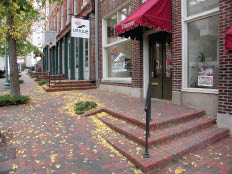
14. Question: Sidewalks will be redesigned and replaced as part of a Main Street improvement program. The existing sidewalk has a cross slope of 5% (1:20). Reducing that cross slope could result in steps at the entrances to abutting businesses. May the steep cross-slope be retained?
Answer: No. While it is usual to coordinate sidewalk improvements with adjacent property owners, a jurisdiction's first responsibility is to the accessibility of its sidewalks. If a comprehensive project is undertaken to improve sidewalks, the municipality must take the steps necessary to provide usable new sidewalks. It is likely that both usable sidewalks and accessible entrances can be obtained through careful engineering. If existing conditions are extreme, a complex solution that makes use of both public (including roadway) and private space may be required. Discussion: There are many ways of maintaining access without exceeding cross slope limits. Narrow sidewalks may be divided lengthwise into conforming and nonconforming widths, with the non-conforming sections serving as entrance ramps; the entire sidewalk may be raised, with steps at the curb if there is parking; or extra width may be borrowed from a roadway or parking lane. Remember that the cross slope requirement applies only to the Pedestrian Access Route. If there is sufficient sidewalk width, steeper cross slopes can be accommodated in the frontage or furnishing zones to match existing building entrances. Community development block grant money may be available to assist adjacent property owners with building ramps on private property.
PROWAAC Subcommittee members developing these recommendations suggested several new FAQs, developed from their project experiences, to expand the breadth of discussion on alterations. Although not part of the Access Board preamble to the draft PROWAG, they may provide useful guidance:
15. Question: State and local governments are covered by Title II of the ADA, but what about Section 504 of the Rehabilitation Act? If a specific project isn't using Federal funds, do the FHWA 504 regulations and associated policies affect the project?
Answer: Yes. As a result of the Civil Rights Restoration Act (CRRA) of 1987, if state or local government public works or highway departments receive any Federal money from any source, not just highway funds, including pass-through funds from the state, the entire program of that local agency is covered. This includes projects undertaken by that agency that do not themselves involve Federal funds. For a full discussion of the impact go to: http://www.fhwa.dot.gov/legsregs/directives/notices/n4720-6.htm.
16. Question: We're re-paving a street. We will be adding/improving curb ramps where needed, but are we required to add accessible on-street parking spaces as part of this project? The parking lane will be re-striped after resurfacing is complete.
Answer: Re-striping on-street parallel parking spaces does not offer any accessibility opportunity (there is no guidance on striping accessibility). However, where perpendicular or angled parking has been provided on a street, it may be feasible after a resurfacing to re-stripe to provide an access aisle for an accessible space (or two) if your jurisdiction doesn't provide sufficient accessible on-street parking (use the new construction scoping to determine the desirable number overall) or if the adjacent land use makes accessible parking particularly desirable in that location. Discussion: The preamble to the DOJ Title II regulation cites adding accessible parking as a program access obligation. Adding accessible parking signs, meters, and curb ramps and relocating curbside barriers, if needed, may be undertaken as program access improvements separately from the resurfacing project, but the striping of an accessible space will give these related needs a higher priority.
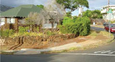
Case Study—Steep Terrain at Corner
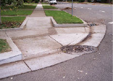
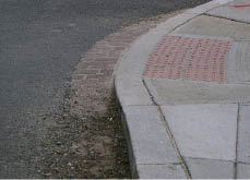
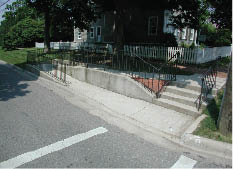
- Before and after photos show a new segment of sidewalk, with a 2% cross slope and curbs for drainage/erosion control, built to facilitate use of a newly installed curb ramp.
- A level landing on the curbed sidewalk connects to the curb ramp.
- The curb ramp is placed at the flattest portion of the street gutter grade along the radius to minimize warp in the curb ramp to the street.
- Still needed: detectable warnings at street edge.
|
| |
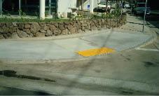
| Case Study—Ponding at a Combined Curb Ramp
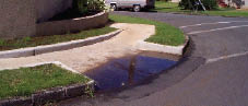
- The existing surface drainage conditions were not considered fully when the combination curb ramp shown was selected for this location and ponding resulted.
|
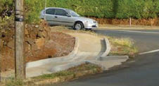
| Case Study—Returned Curb Aids Wayfinding
- This photograph shows a new downtown traffic calming project in Vancouver, WA
- Returned curbs against the landscaped setback provide good orientation cues to crossing pedestrians
- Flares have been minimized in order to make preferred incline/directional ramps possible at this small curb radius
|
| |
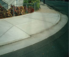
| Case Study—Steep Terrain at Corner
- This new combination (parallel and perpendicular) ramp is installed in an existing sidewalk network as a consequence of resurfacing alterations. It is located at the apex of the corner to insure that pedestrians do not enter the crossing in an active traffic lane.
- Roadway surface and gutter have been raised and blended to meet the new parallel ramp, making this a good example of a combination ramp.
- Where true level landings cannot be provided in alterations, it is particularly important to limit sidewalk cross slope to 2%.
Note: DWS needed. |
| |
| |
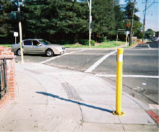
| Case Study—Adding Pedestrian Signals
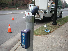
- Stub poles are used at these new curb ramps to properly locate the pedbutton near the departure curb.
- For maximum signal discrimination, each crossing direction should have a separately-mounted device; MUTCD standards require a 10-foot minimum between APS.
- While not specified in ADA or 504 Standards, greater accessibility for those with low vision would be provided if the new signal posts were darker and contrasted with the light sidewalk paving.
|
| |
| Case Study—Combination Curb Ramp
- Existing surface drainage patterns along this corner suggested the likelihood of flooding at the central landing of a parallel ramp so a new combination curb ramp design was specified.
- This is a good approach in limited right-of-way. The short perpendicular curb ramp raises the central landing a few inches above the gutter flow line so it is not flooded.
- The design allows for a level bypass space at the top of the flared side ramp while accommodating the limited width of the existing sidewalk.
- Still needed: detectable warnings at toe.
|
| |
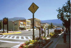
Case Study—Midblock Crossing Criteria
- This APS provides audible and vibrotactile notice of the crossing phase at a midblock crossing where there is no parallel traffic surge to provide a cue. Its locator tone also identifies it as an actuated crossing.
- The pedbutton is installed as close to the departure curb as feasible and is operable from the level landing.
- The pedbutton and tactile arrow are oriented parallel to the crosswalk.
|
| |
| |
CHAPTER 3: DESIGN PROCESS
by Andrew Davis, PE, City of Akron, OH; Jerry Markesino, PE, Otak, Inc.; Jim McDonnell, PE, AASHTO; Bob Sexton, PE, HR Gray (Columbus, OH); Bill Hecker, AIA (Birmingham, AL), Ken Stewart, Council on Citizens with Low Vision, International
The design process for making accessibility improvements in alteration projects is not any different from the design process for traditional street modification projects. Incorporating accessible pedestrian elements in the public right-of-way requires the same reference to standards, technical guidance, and product information that designers follow in every roadway design project. The design and placement of curb ramps into an existing developed streetscape is governed by many of the same considerations as roadway design: controlling horizontal and vertical geometries, surface conditions, and access to intersections, all at the scale of the pedestrian rather than the vehicle.
In an alteration, a balance needs to be struck between pedestrian and vehicle users vying for travel space (and time) within a limited right-of-way already constrained by existing development. A good understanding of the rationale behind accessibility standards will help the designer integrate usability for pedestrians who have disabilities into agency decision making.
Resource: FHWA's ‘Designing Sidewalks and Trails for Access, Part 2' at:
http://www.fhwa.dot.gov/environment/sidewalk2/index.htm
| |
|
| |
This urban arterial passes through a neighborhood that is undergoing rapid revitalization, with many projects under construction temporarily occupying existing sidewalk space. In this example, the contractor has provided a temporary pedestrian route in the curb lane of the roadway, separating it with Jersey barriers and installing a temporary concrete ramp to the street level walkway. Still needed: detectable warnings at the cross street.
|
Gathering Information
A planned alteration project may arise from a long-planned Capital Improvements Program or be a more immediate response to local conditions or community advocacy. When such construction is undertaken, the new work must incorporate accessibility features. Jurisdictions may have additional obligations for existing facilities under the Title II and 504 regulations (see Chapter 2, Alterations).
Therefore, before developing the scope of work for a planned new project, the design team should contact the jurisdiction or agency ADA/504 Coordinator to identify accessibility improvements that may be needed within or near proposed project boundaries, such as:
- curb ramp transition plans and schedules;
- requested individual accommodations, including APS, parking, curb ramps, and sidewalk repairs; and
- bus stop/transit accessibility improvements.
Often, such improvements can be included in a pending project at a more modest cost than undertaking them independently. Evaluate existing conditions near the project site to determine if key accessibility features or needed maintenance could be provided more economically by slightly expanding the project scope of work. Some agencies have developed ‘spot improvement' programs that use resident requests as input to project scoping. Coordination with transit agencies, which have their own ADA obligations for new construction, alterations, and existing facilities and programs, will indicate whether bus stop locations and shelter space and access requirements would best be addressed within a planned project scope. By gathering this information during preliminary project planning, the engineer can avoid potentially costly oversights and under-designs.
Resources: FHWA's ‘Metropolitan Planning' at:
http://www.fhwa.dot.gov/hep/metropol.htm
FTA's civil rights/accessibility page at:
http://www.fta.dot.gov/civilrights/civil_rights_2360.html
Transition Plan, City of Nashville, TN at:
http://www.nashville.gov/gsa/ADA/doj_2047143_final_textonly.htm (see Section VIII: Compliance Strategies for Public Right-of-Way)
State of Hawaii Title II Self Evaluation and Transition Plan at:
http://www.state.hi.us/dlnr/dsp-dp/dsp/rules/draft-transition-plan-self-evaluation.pdf
A newly-funded (2006) National Cooperative Highway Research Project developing guidance for highway agencies on preparing transition plans and meeting program access expectations at:
http://www.trb.org/TRBNet/ProjectDisplay.asp?ProjectID=1247
Planning the Scope of Work
Defining the scope of a planned alteration project establishes the physical and contractual parameters of the work. If right-of-way is to be acquired for a project, it is important to purchase enough to accomplish all project objectives; if an existing right-of-way is to be reapportioned, the scope of work will fix the balance between motor vehicle, cycling, and pedestrian uses. Under-scoping a project may leave or create barriers that will have to be corrected; an oversight that renders a significant part of a planned project inaccessible can entail costly remediation.
New technologies such as central on-street parking pay stations and pedbutton-integrated APS must be carefully placed for usability. Signaling and utility equipment locations and sizes must be anticipated and the accessibility effects of street furniture (benches, bike racks, bus shelters, signage and other appurtenances) must be assessed before right-of-way needs can b e finalized. Private uses of public space for ATM access, sidewalk dining, and newspaper vending all have space and geometric design implications for accessibility.
Street and sidewalk modifications may also affect access to abutting properties. This can raise complex issues of engineering, coordination, and policy, particularly with private sector entities that have obligations under Title III of the ADA to provide accessible approaches and entrances. For example, correcting excessive cross slope as part of a sidewalk improvement project should not result in new steps at entrances to adjacent businesses. A detailed site study that includes consideration of beyond-the-right-of-way implications will best serve public/private coordination efforts and suggest design approaches and solutions (see Chapter 4), which will be helpful in addressing existing constraints in alterations, particularly those of modest scope.
| |
|
| |
This streetscape improvement in a historic downtown works with the street slope to provide individual entrance platforms at existing businesses. Level landings on the upside connect back to the downside with steps. A clear passage of 1.5 m (5 feet) is maintained between the furniture zone at the curb and the stepped entrance platforms.
|
A comprehensive scope of work description will include the following:
- WHAT the proposed project is intended to do, including pedestrian accessibility objectives;
- WHERE the project limits and bounds will be and how new and existing facilities will meet; and
- HOW the project will be funded, including sources, availability, and limitations arrayed against estimates of design and construction costs (note the overview of funding sources for accessibility improvements included in the Appendix).
From this, the planning team will identify possible constraints that may affect roadway, pedestrian, and accessibility objectives. Several design schemes may have to be developed and analyzed before the project scope can be fully determined. The designer should document the decision making process, including the evaluation that led to the selection of the preferred alternative(s).
The scope of work that is defined for an alterations project should reflect pedestrian planning and analysis for accessibility/usability that is commensurate with the overall roadway design work effort.
Examples
Let's use the classic 4Rs of highway design to illustrate how establishing the scope of work relates to access planning (see Appendix for TxDOT's definitions). Most 4R projects involve roadway pavement, although many other elements of construction can also be included:
1. Reconstruction
Reconstruction of roadway facilities is an ambitious undertaking of comprehensive scope under which most objectives can be fully realized for both roadway and sidewalk design. Projects of this complexity should be able to meet or exceed minimum accessibility criteria.
Example: A 1.5-mile length of residential street was reconstructed and re-aligned and water, fire hydrant, and sanitary and storm sewers rehabilitated as part of the project. New curbs and gutters were provided throughout. Accessibility features included new aligned curb ramps with detectable warnings at all crossings. Sidewalks were replaced and driveway aprons reconstructed where needed to meet cross slope limits.
2. Rehabilitation
Rehabilitation projects typically raise subgrade issues. Feasibility is a factor here and ‘work-arounds' will require case-by-case design solutions.
Example: Storm drainage improvements (new inlets) are planned for one side of an existing developed streetscape. Sidewalk and roadway surfaces and subgrade facilities are removed at each corner, but the sidewalks they connect to will remain. When sidewalk segments are replaced or repaired, the new work must provide accessibility/usability. But it must also meet the grades of existing sidewalks at the project boundary. Providing intermediate transition segments between the new and existing work (rather than matching the old) will serve users best. Future work then need only improve the transition segment and the existing sidewalk. In addition, the scope of work for this alteration must include new curb ramps (and the improvement of existing ones, as feasible). The agency should consider adding opposite-side curb ramps to the scope of work, as well.
3. Restoration
Restoration projects return pavement structure, riding quality, or other roadway characteristic in an existing cross-section to near-new condition. Because the work affects the usability of the surface, it is considered an alteration and must include curb ramps at pedestrian crossings.
Example: An existing rutted roadway surface will be restored. Subgrade structure will be improved and a new surface added without disturbing adjacent existing sidewalks. Curb ramps added in an alteration of this limited scope will be usable by many, but may not be optimal in location, wayfinding, slope, width, or other feature until a later alteration to the sidewalk is undertaken.
4. Resurfacing
Most resurfacing will be viewed as an alteration—a change that affects surface usability. However, spot patching and liquid-applied seals are described as maintenance not requiring curb ramps in DOJ technical assistance publications. FHWA guidance distinguishes between structural and non-structural resurfacing.
Temporary Routes
Interim pedestrian accommodations put in place as part of a temporary traffic control plan are considered alterations subject to the ‘maximum extent feasible' limit in the standard. The Manual on Uniform Traffic Control Devices (MUTCD) includes detailed requirements on maintaining pedestrian access through or around a work zone. Project planning must include a temporary usable route that provides the accessible features of the disrupted route, perhaps even including APS.
Resources: MUTCD Chapter 6 at:
http://mutcd.fhwa.dot.gov/HTM/2003r1/part6/part6d.htm
ATSSA work zone safety grant at:
http://www.atssa.com/cs/Federal-Highway-Administration-work-zone-safety
Identification of Constraints and Opportunities
An on-the-spot survey of existing development at the project location is the first step in identifying physical constraints that may require work-arounds or feasibility assessment. There will be a need to evaluate the pedestrian route with respect to width, setback, running grades, cross slopes, lateral and vertical clearances, and sidewalk appurtenances and to identify opportunities to work with the current grade or make use of the parking lane or roadway space, tighter corner radii, and other potential sources of flexibility.
FHWA has developed an inventory process to document existing sidewalk conditions that includes forms and checklists for field information to aid in project scoping, analysis, and design. The forms can be adapted to meet the needs of a particular agency and will be particularly useful in project planning. Because the survey forms do not include pedestrian signalization considerations, agencies adapting its format for local use should add the APS criteria outlined in the NCHRP 3-62 report posted to the website of the Pedestrian and Bicycling Information Center. A separate chapter addresses retrofitting an intersection with APS.
Resources: Sidewalk Inventory Form, in ‘Designing Sidewalks and Trails for Access' at:
http://www.fhwa.dot.gov/environment/bikeped/Access-1.htm
APS criteria in NCHRP 3-62 at:
http://www.walkinginfo.org/aps/home.cfm
Complex engineering design utilizes topographic, elevation, and geometric design information for the design of curb ramps, landings, slopes, clearances, and signal locations in a substantial project. It is important that such surveys include entrance elevations for abutting facilities. Many agencies use an inexpensive rotating laser for this purpose. An electronic level can pinpoint excessive slope and cross slope locations.
During the site design survey and pedestrian route assessment for an alteration project, carefully identify any condition that is likely to affect route accessibility. Examples of existing infrastructure elements that may influence project planning include drainage structures, manholes, utility poles, sewers, water mains, and underground conduits and vaults. In narrow rights-of-way, street trees, building entrances, and basement extensions from adjacent buildings will limit design flexibility unless relocation has been included in the project scope.
Development of Alternatives
When the designer is faced with constraints that affect conformance with accessibility objectives, alternative designs need to be developed and assessed. Chapter 5 addresses accessible design alternatives under a wide range of existing conditions.
Project Documentation
It is common practice in all project designs to document the analysis of certain problem types, including a description of the alternatives considered and decisions made. A street pavement thickness design, for example, will consider the bearing soils, the future truck traffic loads, pavement type, amount of excavation, cost of pavement materials, and other variables. The final selected pavement thickness will be justified by this analysis of relevant variables and their effects on each other. The engineering judgment(s) that lead to the final decision are documented and become part of the permanent project record.
For alteration projects where some improvements may fall short of new construction standards, documentation is very important. The structural design of a bridge includes a very careful analysis of all the components to assure that the bridge will not collapse and cause injury or death. This same standard of care should be exercised with respect to accessible design. Documentation reveals the standard of care that guided engineering judgments made in the course of the work. In the event of a challenge at a future time, documentation can be retrieved from project archives in support of the agency's decisions.
|
This reconstructed residential street in Ohio curves through several intersections skewed by as much as 30 degrees. Although aesthetically pleasing, this posed some design challenges for accessibility. As can be seen in the photograph, low retaining walls were required on many corners. The project included new water mains, fire hydrants and services, sanitary and storm sewer rehabilitation, new curbs and gutters, driveway entrance replacements (to allow ADA-compliant sidewalks across the driveways), and full-depth street reconstruction for approximately 1.5 miles of suburban streets. Paired curb ramps with detectable warnings were constructed at all intersections.
|
Example: As part of a SR25, several existing sidewalk segments will be connected through a small neighborhood commercial area. A tree of substantial caliper shades a 30-inch-wide sidewalk; a retaining wall occupies the property line. The two-lane roadway is also narrow and provides no parking lane. Providing an accessible crossing to a more generous sidewalk on the other side of the street may be an acceptable solution in this instance if the pedestrian crossing is improved and safety considerations are addressed. Alternatively, the town may determine that a preferable course for student safety is to acquire right-of-way and relocate the retaining wall to provide adequate sidewalk width. At the tree, a lesser walkway width (32 inches is the ADAAG minimum for a 24-inch length) can provide the required usability for this limited distance in an existing facility (it wouldn't be an acceptable choice in new construction, however). In the permanent record file for the project, the city engineer should document his efforts to conform to the ADA criteria and his/her decision to build a portion of the sidewalk that is not in strict compliance with new construction standards.
Several state highway agencies have established processes to document infeasibility in a project element or elements under state code requirements or regulations. They offer an opportunity to explain the existing physical or right-of-way constraints that limited conformance to the ADA standards and may be called Design Details of Nonconforming Elements, Design Deviations, Modification of Standards, or other. While useful in the project record, there is no process at the Federal level (where the ADA and Rehabilitation Act are principally enforced) by which review and approval, exceptions, or variances can be granted. For a typical city agency, the designer or the project manager would make the determination of ‘maximum extent feasible', document the engineering judgment that was used in the evaluation of alternatives, and describe the solution that was selected.
The ADA is a civil rights law and by nature it gains clarity through litigation. Careful documentation will not protect against complaint, but evidence of the considerations that led to the specific project solution may be persuasive in court or in discussions with users. Taking a proactive stance towards solving access issues in the right-of-way may allow issues to be addressed and solved without risking a complaint.
Resources: Texas Department of Licensing and Regulation (TDLR) at:
http://www.tdlr.state.tx.us/ab/abrules.htm#6831
Maryland State Department of Transportation at:
http://www.sha.state.md.us/businessWithSHA/bizStdsSpecs/ohd/ada/adaguidelines.asp
Nashville, TN at:
http://www.nashville.gov/gsa/ADA/procedures-forms.htm
Case Study—Narrow Sidewalks
- When this roadway in Washington, DC was resurfaced, existing non-compliant curb ramps were replaced.
- The counterslope of the brick gutter at the toe of this curb ramp was eliminated in order to extend the ramp through the gutter. This allows the ramp to be shorter, because it meets the crown of the roadway at a higher point.
- It also eliminates ponding at the toe.
|
| |
| Case Study—Typical Parallel Curb Ramp
- The limited width of the right-of-way along this street dictated the need for a parallel curb ramp.
- Detectable warnings are shown along the leading edge of the central landing as specified in the draft PROWAG.
|
| |
| Case Study—crowded corners
- This urban corner is crowded with existing signal poles, signal boxes, and utility boxes that limit curb ramp design and placement.
- One solution, shown in the first photo: reduce curb radius to maximize available corner area and ease flares to fit the available space. Still needed: detectable warnings.
- Another option, shown in lower photo: shield ramp sides against pedestrian travel with pedbutton poles and sidewalk furnishings. By eliminating the flares, more corner area is gained. Bonus: returned curb offers useful wayfinding cues for non-visual travel. Note that the curb ramp here is the full width of the crosswalk, another pedestrian benefit. This example is from Barcelona, Spain.
|
CHAPTER 4: DESIGN SOLUTIONS
by Daniel L. Dawson, PE, Otak, Inc & ITE; Elizabeth Hilton, PE, Texas Department of Transportation; Lee R. Kenderdine, PE, and Chuck Yancey, Metropolitan Government of Nashville and Davidson County, Tennessee
Until recently, there have been few design tools available to transportation practitioners for creating accessible pedestrian facilities. For the most part, pedestrian systems have been designed for a user who is agile and who sees, hears, and understands the roadway environment. But just as vehicular ways are engineered for users who have particular requirements—transit, large trucks, and emergency vehicles—so, too do sidewalks need to be planned for a broad range of pedestrians. Implementing accessible design results in a safer and more usable system for all, not just those with disabilities, in part because it requires that a greater level of detail and attention be given to pedestrian issues and improvements.
In the past, design of accessible pedestrian features has been inconsistent because authoritative design guidance has been lacking. And adjusting the geometrics in an existing system—the subject of this technical assistance—takes a much greater degree of creativity, thought, and engineering know-how than starting from scratch on a new project.
| |
|
| |
PROWAAC members observe a thin-film detectable warning retrofit on an existing curb ramp in a pilot project in Portland, OR.
|
Resources
This section includes hypothetical situations and potential design solutions that will vary depending on roadway conditions. The discussions and solutions in this chapter are based on practical applications, research, recommendations, and existing design standards from:
- Building a True Community (January 2001), Public Rights-of-Way Access Advisory Committee's report to the US Access Board;
- Designing Sidewalks and Trails for Access, Part II (August 2001), Federal Highway Administration;
- Notice of Availability of Draft Public Rights-of-Way Accessibility Guidelines (June 2005), US Access Board;
- Manual on Uniform Traffic Control Devices and draft changes approved for 2008;
- Guidelines for Accessible Pedestrian Signals, NCHRP 3-62, University of North Carolina Highway Safety Research Center;
- Guide for the Planning, Design, and Operation of Pedestrian Facilities (July 2004), American Association of State Highway and Transportation Officials; and
- Chapter 6 of this special report
Accessible Design is a Safety Best Practice
Pedestrian interactions with motor vehicles bring safety risks. For instance, the lack of pedestrian signage and signal information in usable formats puts people with visual disabilities at a greater risk than those who can see. The 30-year-old cuckoo-chirp technology for providing crossing information to people with visual disabilities has been replaced by modern electronics that tick, talk, vibrate, audibly advertise their presence, adjust to ambient sound, and provide a wide range of other information (mapping, street names, special messaging, audio beaconing). Over 30 manufacturers now provide stand-alone or pedbutton integrated APS devices, including some that are receiver based for individual use.
The MUTCD includes standards and guidance for the placement and application of APS in Chapter 4. APS technology can significantly improve the access and safety of pedestrians with impaired vision because the crossing information is provided in multiple formats. As with other accessible design criteria, the usability of APS technology will depend on attention to detail and consistent inclusion of APS when designing and constructing signal systems. Where push buttons are placed at crosswalks and curb ramps, two buttons at each corner (one at each curb ramp) are critical for people with disabilities to understand which street crossing has the ‘walk' phase and to position themselves at the crossing before the walk phase starts.
The boundary between the sidewalk and roadway is not easy to detect if a person cannot see it, and stepping into the street without knowing it can be a significant safety problem. People with visual disabilities relied on curbs for that information before the advent of curb ramps. Detectable warnings (DWs), a pattern of low truncated domes, placed where the curb has been eliminated to provide wheelchair access, provide underfoot information on where the sidewalk ends and the street begins.
| |
|
| |
Curb ramp with returned curb adjacent to landscape strip
|
The safety of wheelchair users is compromised when all four wheels do not maintain contact with the ground. This happens when sidewalk surfaces and transitions to the curb ramp and crosswalk are warped or there is a change in level—very common occurrences in the pedestrian environment. Steep grades and cross slopes can create similar stability, control, and tipping and falling problems for ambulatory pedestrians who use mobility devices. Many of these situations could be eliminated with greater attention paid to detailing pedestrian facilities during the design phase.
All these issues are accessibility and safety issues; the two are difficult to separate from one another in the pedestrian environment.
Information in This Chapter
The Case Studies used as examples in this report represent different, and not always optimal, approaches to streetscape alterations under a range of existing conditions. Some solutions are more successful than others and PROWAAC Subcommittee members did not agree on every photograph included here. Their use in this document should not be interpreted to indicate that they represent satisfactory or complete solutions. Each situation needs to be evaluated on a case-by-case basis using applicable standards, or, where standards are absent or inapplicable, best practices developed in concert with users and other experts.
Please note that in most design solutions, crosswalk markings are shown. To avoid giving the user the impression that a certain type of crosswalk marking is preferred, different types of markings are shown. These illustrated crosswalk markings are applied at random in the illustrations and aren't intended to convey that one is preferable over another for the specific design solution.
We have tried to use common industry terms, but you may find regionalisms in the text (we have used ‘bulb-out' instead of ‘curb extension', for instance). Your agency or firm may also characterize alterations differently. Our use of ‘alterations' is derived from the civil rights legislation and does not conform with the common industry practice of viewing ‘re-surfacing' as a maintenance item.
It isn't always possible to find photo illustrations that comply fully with accessibility criteria. So you will see in these pages curb ramps without detectable warnings and pedestrian signals and push buttons that provide only visual information. We've tried to note these discrepancies in the text and captions.
Design approaches illustrated here are familiar ones that exist in every pedestrian engineering toolbox.
Legend for Chapter 4 Design Solutions |
 APS* APS*
|
|
 Curb Curb
|
 DWS DWS
|
|
 Right-of-Way Right-of-Way
|
* Face of pushbutton device should be aligned with crosswalk direction.
Reducing Curb Radius
In many solutions offered here, the curb return radius has been reduced to aid in solving the design issues. If curb or roadway reconstruction can be included in a project's scope, it may be possible to reduce the curb radius and so improve pedestrian access and safety. Reduced curb radii generally provide a larger area for pedestrian space (including curb ramps) at an intersection and are encouraged where turning movements and street widths allow. This is generally a benefit for all pedestrians and may even reduce delay for vehicles if crossing distances are less. However, designers will need to consider ways of satisfying turning radius requirements for larger vehicles.
Installing Accessible Pedestrian Signals
Wayfinding for pedestrians with visual impairments is significantly improved with the incorporation of APS at signalized intersections; APS are the most commonly-requested accommodation under FHWA's 504 regulation. Draft PROWAG specifies APS that are integrated with the pedestrian push button and include a tactile arrow and audible and vibrotactile indications. Audible signals mounted on the pedestrian signal head (as has been typical in the U.S.) would not meet the PROWAG provisions for placement or for vibrotactile indications. These new types of devices are intended to be installed close to the departure location and are typically only audible 6 to 12 feet from the push button, unless special beaconing features are installed. Push button locator tones are also a required feature and volumes of the walk indication and push button locator tone automatically adjust in response to ambient sound (+2-5dB).
| |
|
| |
APS may need to be installed on a new stub pole at the departure curb for optimum usability.
|
The drawings in this chapter and in Chapter 6 show ideal placement of the push button-integrated APS in each illustrated solution. Placing the APS close to the landing and on the side away from the center of the intersection is best. The process of determining APS placement should include a careful study of:
- directionality (aligning the tactile arrow with the direction of travel on the crosswalk);
- avoiding ambiguity caused by placing two APS close together, where which button is sounding cannot be distinguished;
- limiting the need for significant reorientation from the push button to the curb; and
- reach and surface conditions for a pedestrian using a wheelchair.
The MUTCD 2003 specifies that two APS devices on a corner should be separated by at least ten feet. The separation often can be provided by installation of a stub pole for at least one of the APS devices, with the other located on the signal pole. In alterations situations, constraints may prevent this separation of devices. If two APS on a corner must be placed closer than ten feet, speech walk messages and additional custom features providing specific information about the crossing are recommended. Additional information can be found in the final report of the National Cooperative Highway Research Program Project 3-62, Guidelines for Accessible Pedestrian Signals.
When installing APS, the designer should select a unit with a push button locator tone, audible and vibrotactile WALK indications, tactile arrow, and automatic volume adjustment. Other features, such as audible beaconing upon request should also be analyzed and considered during the design phase. In all cases, the face of the device and the tactile arrow should be aligned with the direction of travel on the crosswalk, not aimed at the crosswalk or aligned with the ramp orientation. This becomes increasingly important if the location of the button is compromised by some existing physical constraint that prevents the use of an ‘ideal' location in an alteration.
| |
|
| |
This wide Main Street in a historic town has been improved with the addition of medians and parking-lane landscaping at a midblock crossing. The curbed planters have been cut through at the crossing and along the curb to maintain drainage; the edges provide good non-visual wayfinding cues. Still needed: detectable warnings at the street edge, where there is no indication of the change from pedestrian to vehicular way.
|
Bulb-outs/Curb Extensions
In several design solutions, the use of bulb-outs is proposed. Extending the curb at a crossing works well at locations with on-street parking. Other design solutions suggest tapering the street width to allow additional space at the curb returns. In each of these applications, the curb has been moved closer to the centerline of the street. This will likely result in a change in the drainage flow along the street surface. Sidewalk cross slope may be improved, since it is likely that the roadway surface being used is more level. Some curb height may be sacrificed.
Combination Curb Ramps
The use of combination curb ramps (combining a parallel ramp in the sidewalk, a level landing for a turn, and a short perpendicular run to the street) can make the most of limited sidewalk width.
Reduced Curb Height and Installation of Bollards
Reducing curb face exposure to limit the need for a longer curb ramp can lead to vehicles riding up on the curb corners as in flush curb applications. Some jurisdictions may use bollards to avoid such incursions. If they are provided, it is critical that the bollards have high visual contrast with the background.
| |
|
| |
Sometimes difficult topography requires extraordinary solutions. In this photograph of an older Ohio residential neighborhood, the existing roadways are much lower than the sidewalks and separated by wide sloping lawns. New stairs and ramps—both with handrails—make the connection to the street crossing for pedestrians.
|
| |
 |
| |
A perpendicular curb ramp with side flares and a top landing is shown. The ramp run does not end at the curb, but extends across the gutter to meet the street at a higher elevation, making it possible to accommodate a perpendicular ramp and landing in a narrow sidewalk and eliminating the effects of the gutter counterslope. Short reverse flares extend back to the curb face.
|
Extending the Curb Ramp Across the Gutter Pan
Some of the design solutions include extending the curb ramp across the gutter pan where insufficient space exists to provide both a curb ramp and a landing. In most cases, the height of the curb ramp across the gutter pan will be minimal (two inches or less) but the side slopes of this extension should be tapered out at a minimum slope of three horizontal to one vertical. Generally, placing an obstruction in the flow line of the gutter is undesirable, but it is a small sacrifice for providing a suitable curb ramp and does avoid ponding at the toe, which can hide a problematic lip or freeze in cold weather. Consider the drainage impacts of the installation and consider adding a catch basin just upstream of the obstructed gutter pan. Another solution is a narrow (one inch) cast iron trench drain across the ramp toe to collect drainage.
Design Problems
The design solutions for the hypothetical problems described in the following pages have been developed in conformance with recommendations of the PROWAAC (Building a True Community) and the draft PROWAG published by the Access Board in November 2005. During the PROWAAC meetings, relevant MUTCD 2003 provisions were harmonized with PROWAG technical specifications, a process that continues with the preparation of the 2008 MUTCD. The Subcommittee also coordinated its work with development of the AASHTO pedestrian guide.
The problem statements are organized as five different types, based largely upon the nature of the principal constraint:
- Limited right-of-way
- Above-ground obstructions
- Push buttons are not accessible
- Excessive roadway slope
- Underground obstructions
Constraint—Limited Right-of-Way
Acquire Additional Right-of-Way
Problem Statement
Not enough room for curb ramp and landing
Problem and Design Solution Discussion
Existing street improvements, including vehicle lanes and sidewalks, consume the entire right-of-way. Often there is insufficient space for the installation of an accessible curb ramp and landing at a street intersection that will meet new construction standards. Increasing right-of-way width can provide sufficient space to create curb ramp and landing dimensions that provide ideal construction solutions. Often adjacent private developments in the permitting stage offer opportunities to acquire the right-of-way at no cost.
Design Solution 1.01

Application Considerations
- Acquire sidewalk easements.
- Acquire right-of-way dedication.
- Purchase additional right-of-way.
- Expanded sidewalk area will provide a larger area for pedestrians to gather/wait, and more room for curb ramps, landing, signal equipment, etc.
- May require alterations to building and/or other structural features located at or near corner.
- Sometimes acquisition of right-of-way is a long and costly process or not feasible.
Related Design Standards
- MUTCD
- Local Codes and Standards
Related Design Guidelines
Constraint—Limited Right-of-Way
Elevate Intersection to Sidewalk Level
Problem Statement
Not enough room for landing and curb ramp slope will be too steep.
Problem and Design Solution Discussion
Existing street improvements, including vehicle lanes and sidewalks, consume the entire right-of-way. Often there is insufficient space for the installation of an accessible curb ramp and landing at a street intersection that will meet new construction standards. Another potential solution is to raise the entire street grade at the intersection to make the sidewalk elevation flush with the street elevation, thus eliminating the spatial needs for curb ramps. It is critical in this application to provide detectable warning surfaces to provide a detectable alert to blind and visually impaired travelers, which indicate that they are entering a street. Raising the entire intesection can be a wayfinding issue for the blind; raised crosswalks alone are better as blind pedestrians can recognize the curb between the raised crosswalks.
Design Solution 1.02

Applicacion Considerations
- Potentially increases construction costs.
- May require street drainage changes/additions.
- Continuous detectable warning surfaces are required to delineate pedestrian area from the street area.
- May require the installation of APS signal equipment.
- Consider raised crosswalks as an alternative.
- If provided, bollards should have high visual contrast to background (dark/light or light/dark).
Related Design Standards
- MUTCD
- Local Codes and Standards
Related Design Guidelines
Constraint—Limited Right-of-Way
Extend Curb Ramp Over Gutter Pan
Problem Statement
Not enough room for landing and curb ramp.
Problem and Design Solution Discussion
Existing street improvements, including vehicle lanes and sidewalks, consume the entire right-of-way. Often there is insufficient space for the installation of an accessible curb ramp and landing at a street intersection that will meet new construction standards. In this case, a building with entry is located in the area where a curb ramp needs to be constructed. As a result, the back of the sidewalk is constrained and cannot be lowered. Thus, a parallel curb ramp is not possible. A solution is to construct a curb ramp that extends through the curb and over the gutter pan.
Design Solution 1.03

Application Considerations
- The extension of the curb ramp through the gutter may have an impact on drainage.
- Detectable warnings must be placed at the back of curb line even though the curb ramp extends beyond this point to alert pedestrians with limited vision that they are stepping into the street.
- May require the installation of APS signal equipment.
- Avoid extending projecting curb ramp into travel lane.
- May encourage pedestrians to wait in the street portion of curb ramp.
- Stop bar may increase driver awareness of curb ramp.
- Consider using in conjunction with on-street parking to allow room for projecting curb ramp.
Related Design Standards
- MUTCD
- Local Codes and Standards
Related Design Guidelines
Constraint—Limited Right-of-Way
Use Combination Curb Ramp
Problem Statement
Not enough room for landing and curb ramp.
Problem and Design Solution Discussion
Existing street improvements, including vehicle lanes and sidewalks, consume the entire right-of-way. Often there is insufficient space for the installation of an accessible curb ramp and landing at a street intersection that will meet new construction standards. In this example, the combination of lowering the sidewalk and shortening the length of the curb ramp allows for sufficient space for a landing behind the curb ramp.
Design Solution 1.04

Application Considerations
- The face of the building must accommodate the additional exposure of lowering the sidewalk four inches in front. Detectable warning placement is important to alert pedestrians with visual impairment that they are about to cross the street.
- Providing some perpendicular ramping eliminates the potential for ponding at the landing.
- If provided, bollards should have high visual contrast to background (dark/light or light/dark).
- Placement of APS close to buildings and other hard vertical surfaces creates directional sound interpretation issues for blind pedestrians and should be avoided.
Related Design Standards
- MUTCD
- Local Codes and Standards
Related Design Guidelines
Constraint—Limited Right-of-Way
Lower Sidewalk to Street Surface (Blended Transition)
Problem Statement
Not enough room for landing and curb ramp.
Problem and Design Solution Discussion
Existing street improvements, including vehicle lanes and sidewalks, consume the entire right-of-way. Often there is insufficient space for the installation of an accessible curb ramp and landing at a street intersection that will meet new construction standards. Another potential solution is to lower the sidewalk grade at the intersection to make the sidewalk elevation flush with the street elevation, thus eliminating the spatial needs for curb ramps. Detectable warning surfaces provide a critical message to blind travelers where the sidewalk is flush with the street.
Design Solution 1.05

Application Considerations
- Potentially increases construction costs.
- May require street drainage changes/additions.
- Continuous detectable warnings are required to delineate pedestrian area from the street area.
- Placement of APS close to buildings and other hard vertical surfaces creates directional sound interpretation issues for blind pedestrians and should be avoided.
- If provided, bollards should have high visual contrast to background (dark/light or light/dark).
Related Design Standards
- MUTCD
- Local Codes and Standards
Related Design Guidelines
Constraint—Limited Right-of-Way
Parallel Curb Ramp
Problem Statement
Not enough room for landing and curb ramp.
Problem and Design Solution Discussion
Existing street improvements, including vehicle lanes and sidewalks, consume the entire right-of-way. Often there is insufficient space for the installation of a perpendicular curb ramp and landing at a street intersection that will meet new construction standards. A potential solution would be to design a parallel curb ramp instead of a perpendicular curb ramp.
Design Solution 1.06

Application Considerations
- All users of the sidewalk will have to traverse the curb ramp. If bypassing the crossing, the user would have to descend to the landing and ascend back to the sidewalk level.
- Possible variations on the parallel curb ramp that could be used if sufficient space is available are a split sidewalk or a combination curb ramp.
- If existing drainage is poor, debris and silt can accumulate in the landing.
Related Design Standards
- Local Codes and Standards
Related Design Guidelines
Constraint—Limited Right-of-Way
Reduce Street Width and Provide Combination Curb Ramp
Problem Statement
Not enough room for landing and curb ramp.
Problem and Design Solution Discussion
Existing appurtenances limit travel space and installation of accessible landings and curb ramps at corners. The building location has limited the location of curb ramps and landings. Existing street improvements consume the entire right-of-way. In this example, street width has been reduced to provide adequate space to use a combination sidewalk ramp and curb ramp to achieve the required 1:12 slope from curb height to street grade.
Design Solution 1.07

Application Considerations
- May require street drainage changes/additions.
- Significantly increases construction costs.
- Expanded sidewalk area will provide a larger area for pedestrians to gather/wait, and more room for curb ramps, landing, and signal equipment.
- Providing curb extensions reduces roadway width, which works well if the street has on-street parking. If not, then this solution may not be possible.
- This application assumes that the sidewalk can slope adjacent to the building.
- Reduces crossing distance for pedestrians.
- Curb extensions normally provide effective traffic calming.
- The transition from the existing sidewalk to the curb ramp landing elevation is not required to exceed 15 feet in length.
- Placement of APS close to buildings and other hard vertical surfaces creates directional sound interpretation issues for blind pedestrians and should be avoided.
Related Design Standards
- MUTCD
- Local Codes and Standards
Related Design Guidelines
Constraint—Limited Right-of-Way
Reduce Street Width and Provide Combination Curb Ramp
Problem Statement
Not enough room for landing and curb ramp.
Problem and Design Solution Discussion
Existing street improvements consume the entire right-of-way. In this example, the building is built out to the right-of-way and there is inadequate space to provide curb ramps. This solution uses a reduced curb radius and combination curb ramp to accommodate the shortened perpendicular portion of the curb ramp.
Design Solution 1.08

Application Considerations
- Expanded sidewalk area will provide a larger area for pedestrians to gather/wait, and more room for curb ramps, landing, signal equipment.
- May require alterations to building doorways located at or near corner.
- Increases motorist's visibility of pedestrians at the corner.
- May require street drainage changes/additions and increased construction costs.
- May not accommodate all right turning vehicles. Check vehicle types for turning radius requirements. If receiving street is multi-lane, a smaller right turn radius is less problematic.
- Placement of APS close to buildings and other hard vertical surfaces creates directional sound interpretation issues for blind pedestrians and should be avoided.
Related Design Standards
- MUTCD
- Local Municipal Specifications and Standards
Related Design Guidelines
Constraint—Limited Right-of-Way
Parallel Curb Ramps Provide Access to Parking Space
Problem Statement
Insufficient sidewalk space to accommodate a perpendicular curb ramp to serve the 13-foot wide on-street accessible parking space.
Problem and Design Solution Discussion
Accessible parking spaces with access aisles and accessible connections to the sidewalk must be provided at on-street parking locations where the existing sidewalk widths are 14 feet or greater. For sidewalks less than 14 feet in width, accessible parking spaces must be provided, but access aisles are not required. When access aisles are not provided to connect to the PAR, the accessible parking space must be located at the end of a block face to utilize the corner curb ramps. Where adequate sidewalk width exists, accessible sidewalk connections and the PAR can be created by either providing a curb extension out to the edge of the parking lane and reducing the sidewalk width to provide space for unloading and using the PAR. Another option is to simply reduce the sidewalk width by four feet and use this reduced width as the PAR and unloading area.
Design Solution 1.09

Application Considerations
- May require some regrading of street to accommodate revised drainage flow patterns.
- May require the addition of new storm drainage collection facilities.
- Provides ability for wheelchair and scooter users to unload on the street pavement outside of traffic lanes and have ramped connections to the sidewalk.
- Reduces the width of sidewalk available for general use.
- Parking space should be set back from the crosswalk and/or stop sign (if one exists) to maintain safe visibility.
Related Design Standards
- Local Municipal Parking Codes
- Local Municipal Design Standards
- Local Codes and Standards
Related Design Guidelines
Constraint—Above Ground Obstructions
Relocate Obstruction
Problem Statement
Existing appurtenances limit travel space and installation of accessible landings and curb ramps at corners.
Problem and Design Solution Discussion
Existing elements at a corner cannot be eliminated. In this example, the fire hydrant was moved to a location that eliminated its interference with the curb ramp installation. Because there is insufficient space for a full landing and conventional curb ramp, some ramping is provided in the sidewalk and some ramping is provided in the furnishing area.
Design Solution 2.01

Application Considerations
- Increased cost to relocate existing fire hydrants, power poles, utilities, vaults, furniture, signage, etc.
- Combination curb ramp avoids conflict with stairway and provides perpendicular section of curb ramp, with related drainage benefits.
- Utility relocations can require extensive coordination.
Related Design Standards
- MUTCD
- AWWA
- Local Municipal Specifications and Standards
Related Design Guidelines
Constraint—Above Ground Obstructions
Single Curb Ramp at Apex
Problem Statement
Existing appurtenances limit travel space and installation of accessible landings and curb ramps at corners.
Problem and Design Solution Discussion
Obstructions in the intended paths of travel prevent the construction of a curb ramp for each direction of travel. However, the area at the apex of the corner is clear of existing obstructions. A single perpendicular curb ramp that serves both crossings may be the only alternative. Keep in mind, however, that two curb ramps, if possible, are always preferable to a single curb ramp at the apex.
Design Solution 2.02

Application Considerations
- Single curb ramps serving two crossings are the least preferred.
- Will not provide directional cue to pedestrians with visual impairments.
- May not accommodate all right turning vehicles. Check vehicle types for turning radius requirements. If receiving street is multi-lane, a smaller right turn radius is less problematic.
- Push buttons have been located as far apart as possible while maintaining close proximity to the crosswalk and the curb ramp landing. Separation of push buttons is desirable to clearly indicate which crossing is served by each button.
Related Design Standards
- Local Municipal Specifications and Standards
Related Design Guidelines
Constraint—Above Ground Obstructions
Install Combination Curb Ramp
Problem Statement
Existing appurtenances limit travel space and installation of accessible landings and curb ramps at corners.
Problem and Design Solution Discussion
Placement of signal controller cabinets in the past failed to take into consideration the needs of pedestrians. Signal controller cabinets have been located for reasons of economy and convenience. Many of these units now block, or to a lesser degree, project into the PAR. If the base of the cabinet is sufficiently deep, it may be possible to use a combination sidewalk and curb ramp to achieve the appropriate layout. By ramping the sidewalk down three inches in the vicinity of the cabinet, it will be possible to reduce the length of curb ramp about three feet, thus providing adequate space for a landing.
Design Solution 2.03

Application Considerations
- Will require a suitable cabinet base to work around.
- Does not require acquisition of additional right-of-way.
- Does not require rewiring of the controller.
- Since APS post at back of landing would be too close to controller, move to front of landing at back of flare.
Related Design Standards
- MUTCD
- Local Municipal Specifications and Standards
Related Design Guidelines
Constraint—Above Ground Obstructions
Relocate Signal Control Cabinet
Problem Statement
Existing appurtenances limit travel space and installation of accessible landings and curb ramps at corners.
Problem and Design Solution Discussion
Placement of signal controller cabinets in the past failed to take into consideration the needs of pedestrians. Signal controller cabinets have been located for reasons of economy and convenience. Many of these units now block, or to a lesser degree, project into the PAR. The cabinet can be moved back to provide sufficient clearance for a landing at the back of the curb ramp. In this example, the sidewalk has also been extended to provide the landing space.
Design Solution 2.04

Application Considerations
- May require rewiring of the signal to the cabinet.
- Results in a typical curb ramp and landing installation.
- May require purchase of additional right-of-way.
Related Design Standards
- MUTCD
- Local Municipal Specifications and Standards
Related Design Guidelines
Constraint—Above Ground Obstructions
Relocate Signal Control Cabinet
Problem Statement
Existing appurtenances limit travel space and installation of accessible landings and curb ramps at corners.
Problem and Design Solution Discussion
Placement of signal controller cabinets in the past failed to take into consideration the needs of pedestrians. Signal controller cabinets have been located for reasons of economy and convenience. Many of these units now block, or to a lesser degree, project into the PAR. When a cabinet blocks passage along a sidewalk or at an intersection, several options exist to achieve adequate clearance. Sidewalk can be extended to wrap around the back of the cabinet, or the cabinet may be rotated to provide clearance. If the cabinet is a pole-mounted cabinet, it could be relocated to a pedestal-mounted cabinet (built over a base, not mounted on the pole), or it could be rotated to be on the side of the pole that provides maximum passage clearance to the sidewalk.
Design Solution 2.05

Application Considerations
- If a cabinet is pole mounted more than 27 inches above the ground and projects into the traveled way, a detectable curb or other cane detectable feature must be located beneath the cabinet for detectability.
- Rotation of cabinets may require rewiring of the signal system.
Related Design Standards
- MUTCD
- Local Municipal Specifications and Standards
Related Design Guidelines
Constraint—Above Ground Obstructions
Use Parallel Curb Ramps
Problem Statement
Existing appurtenances limit travel space and installation of accessible landings and curb ramps at corners.
Problem and Design Solution Discussion
Placement of signal controller cabinets in the past failed to take into consideration the needs of pedestrians. Signal controller cabinets have been located for reasons of economy and convenience. Many of these units now block, or to a lesser degree, project into the PAR. If the cabinet blocks the space needed for a landing at the upper end of a curb ramp, but provides adequate width for the PAR, use of parallel curb ramps could provide an accessible corner.
Design Solution 2.06

Application Considerations
- Since the sidewalk will be lower adjacent to the cabinet, the cabinet base may require modification.
- Earth cover over existing conduits running to the cabinet may be less than desirable.
- Detectable warnings required to delineate pedestrian area from the street area.
Related Design Standards
- MUTCD
- Local Municipal Specifications and Standards
Related Design Guidelines
Constraint—Above Ground Obstructions
Add Curb Extensions/Bulb-outs
Problem Statement
Existing appurtenances limit travel space and installation of accessible landings and curb ramps at corners.
Problem and Design Solution Discussion
Placement of signal controller cabinets in the past failed to take into consideration the needs of pedestrians. Signal controller cabinets have been located for reasons of economy and convenience. Many of these units now block, or to a lesser degree, project into the pedestrian access route. Additional space for accessibility features can be created by installing curb extensions (bulb-outs) where it is possible to reduce the width of the street.
Design Solution 2.07

Application Considerations
- May require street drainage changes/additions.
- Significantly increases construction costs.
- Expanded sidewalk area will provide a larger area for pedestrians to gather/wait, and more room for curb ramps, landing, and signal equipment.
- Providing curb extensions reduces roadway width and this will work well if the street has on-street parking.
- Pedestrians will be more visible to motorists.
- Motorists will be more visible to pedestrians.
- Curb extensions normally provide a traffic calming effect.
- Reduces crossing distance for pedestrians.
Related Design Standards
- MUTCD
- Local Municipal Specifications and Standards
Related Design Guidelines
Constraint—Above Ground Obstructions
Provide Blended Transition
Problem Statement
Accessible curb ramps and landings constrained by features that can't be modified.
Problem and Design Solution Discussion
Existing historic features or significant trees limit travel space and the installation of accessible landings and curb ramps at corners. In this example, a historic building is located close to the curb face at the intersection. The solution here is to provide a transition ramp from each approach direction and provide a blended transition at the corner.
Design Solution 2.08

Application Considerations
- Will decrease pedestrian travel capacity. (Pedestrian pairs and groups will need to travel in single file.)
- Increases conflicts between pedestrians traveling in opposite directions.
- Building face/foundation must be able to accommodate changing sidewalk grades.
- A similar solution would be to raise the intersection to sidewalk level.
- More difficulty for blind travelers to determine directionality.
- For APS, provide audible message at this
location since inadequate separation between
push button locations makes it difficult for
blind people to determine which push button guides each crossing.
- Pushbutton location either at curb or near face of building.
Related Design Standards
- Uniform Building Code
- Local Codes and Standards
Related Design Guidelines
Constraint—Push Buttons Are Not Accessible
Add Stub Poles
Problem Statement
Pedestrian actuated signal push buttons at inappropriate locations.
Problem and Design Solution Discussion
Pedestrian actuated push buttons are often located on a central signal pole away from the curb ramps and do not facilitate efficient use by all pedestrians, including those with disabilities. Often the travel distance from the button location to the street is excessive. Also, crossing orientation is difficult for a blind pedestrian since the locator tone and both buttons are at the same location. Installation of stub poles with APS equipment and push buttons closer to the crossing solve these problems.
Design Solution 3.01

Application Considerations
- Locate stub poles adjacent to level landing areas of curb ramps so wheelchair users can access buttons at a location where the wheelchair will remain stationary.
- Higher cost due to removal and replacement of sidewalk to install underground connections to stub pole.
- For parallel curb ramps, locate the stub poles at the back of sidewalk (landing).
Related Design Standards
- MUTCD
- Local Codes and Standards
Related Design Guidelines
Constraint—Push Buttons Are Not Accessible
Add Curb Extensions/Bulb-outs
Problem Statement
Pedestrian actuated signal push buttons
not at optimal locations.
Problem and Design Solution Discussion
Pedestrian actuated push buttons are often located on a central signal pole away from the curb ramps and do not facilitate efficient use by all pedestrians, including those with disabilities. In addition, corners often become the location for multiple poles that block the installation of curb ramps. One solution is to add curb extensions at the intersection to provide sufficient space for curb ramps and stub poles for APS and push buttons.
Design Solution 3.02

Application Considerations
- Locate stub poles adjacent to level landing areas of curb ramps so wheelchair users can access buttons.
- Higher cost due to removal and replacement of sidewalk to install underground connections to stub pole, but also could be a cost savings compared to the cost of multiple pole relocations.
- Potential street drainage impacts.
- Reduces crossing distances and times for pedestrians.
- Pedestrians will be more visible to motorists.
- Curb extensions normally provide a traffic calming effect.
- Works well if there is on-street parking.
Related Design Standards
- MUTCD
- Local Codes and Standards
Related Design Guidelines
Constraint—Excessive Roadway Slope
Add Curb Extensions/Bulb-outs
Problem Statement
Existing street running grade
does not support level landings.
Problem and Design Solution Discussion
Street running grades in excess of 5% create challenges in the design and construction of accessible features at intersections. In some situations, the use of bulb-outs can create larger and flatter pedestrian areas at corners, which can accommodate flat landings and acceptable slopes on curb ramps.
Design Solution 4.01

Application Considerations
- Corner curb extensions, or bulb-outs will provide additional space and allow for construction of a level landing.
- Expanded sidewalk area will provide a larger area for pedestrians to gather/wait, and more room for curb ramps, landing, and signal equipment.
- May require alterations to building doorways located at or near corner. Improves motorist's view of pedestrians at the corner.
- Increases construction costs.
- May provide an option to alter vehicle turning geometry and increase pedestrian gathering area.
- The turning radius in this example is effectively shortened and may not accommodate all right turning vehicles. Check vehicle types for turning radius requirements. If receiving street is multi-lane, a smaller right turn radius is less problematic.
Related Design Standards
- MUTCD
- AASHTO
- PROWAAC
- Local Municipal Specifications and Standards
Related Design Guidelines
Constraint—Excessive Roadway Slope
Problem Statement
Existing street running grade does not support level landings and acceptable crossslopes on crosswalks.
Problem and Design Solution Discussion
Street running grades in excess of 5% create challenges in the design and construction of accessible features at intersections. Modifying the street profile for the stop controlled street to ‘table' the crosswalk providing a 2% or less cross slope in the crosswalk improves the crosswalk and allows for acceptable curb ramp at each end of the crosswalk. Note that the 2% cross slope only needs to be achieved within the 4-foot PAR, not across the entire crosswalk.
Design Solution 4.02

Application Considerations
- Revise intersection grades to create raised crosswalk.
- May create less desirable profile for vehicular traffic.
- May require street drainage changes/additions.
- Increases construction costs.
- Added difficulty in application of future pavement overlays.
- May introduce travel/grade change problems for bicycles.
- For steeper grades, longer grade transitions including vertical curves may be required.
- May have to rebuild subgrade.
- May impact drainage.
Related Design Standards
- MUTCD
- Local Municipal Specifications and Standards
Related Design Guidelines
Constraint—Excessive Roadway Slope
Regrade Roadway Profile to Provide Acceptable Cross Slope Across Intersection
Problem Statement
Existing street grade does not support
acceptable crossslopes on crosswalks.
Problem and Design Solution Discussion
In this example the existing north-south leg of the intersection has a 5% grade. One solution is to table the entire intersection approaches to accommodate flattened crosswalk cross slopes for both the north and south approaches to the intersection. Ideally, the tabling would be accomplished by lowering the upper half of the intersection and raising the lower half of the intersection. The achieved grade through the intersection would be 2%.
Design Solution 4.03

Application Considerations
- Most appropriate when street is being reconstructed.
- Most appropriate for lower speed roadway.
- Revise entire intersection to create a level or flat surface.
- Alteration of all approaches may be necessary to vertically blend grades with the intersection.
- May require street drainage changes/additions.
- Will likely result in significant engineering and construction costs.
- Construction of flat intersection surface will potentially affect underground utilities, surface facilities, building entrances, transit facilities, and landscape features.
- More suitable with fewer lanes.
Related Design Standards
- Local Municipal Specifications and Standards
Related Design Guidelines
Constraint—Excessive Roadway Slope
Mill Street Crown to Reduce Crosswalk Running Slope
Problem Statement
Existing street running grade
does not support accessible crossings.
Problem and Design Solution Discussion
Many existing streets have been resurfaced several times and the resurfacing has resulted in the crown slope of the street getting steeper and steeper. As a result, crossing streets with steep crowns can become physically challenging when overlays have steepened the crown to more than 5%. One solution to reduce the crown slope and the resulting effort of a pedestrian in a manual wheelchair, is to mill the pavement surface back to a 2% crown as part of the resurfacing process.
Design Solution 4.04

Application Considerations
- Reduces the crossing time of a pedestrian in a manual wheelchair.
- Improves entrance and exit characteristics for vehicles parked at the curb.
- Milled asphalt concrete pavement can be recycled as base material or as part of the asphalt concrete mix.
- Increases the cost of overlay projects due to increased cost of pavement milling.
- Makes the transition from the gutter to the street crown smoother, reducing the angle point.
- Transition back to existing crown over the appropriate length of roadway for vehicular operations.
- New pavement surface must be flush with curb ramp.
Related Design Standards
- Local Municipal Specifications and Standards
Related Design Guidelines
Constraint—Excessive Roadway Slope
Provide Median Refuge Area
Problem Statement
Existing street running grade
does not support accessible crossings.
Problem and Design Solution Discussion
Many existing streets have been resurfaced several times and the resurfacing has resulted in the crown slope of the street getting steeper and steeper. As a result, crossing streets with steep crowns can become physically challenging when overlays have steepened the crown to more than 5%. If it is not feasible to re-crown the street, it may help to provide a median refuge area for pedestrians, particularly on wider streets, as the steeper cross slope causes manual wheelchair users and others with little stamina, to take more time to cross the street and expend more energy.
Design Solution 4.05

Application Considerations
- At signalized intersections, may allow for reduced pedestrian clearance interval since pedestrians can stop in the median.
- At signalized intersections, provide pedestrian push buttons at median refuge area.
- More benefit accrues for wider street applications.
- At uncontrolled or stop controlled intersections, provides more crossing opportunities and less waiting time for all pedestrians.
- Detectable warning surfaces are required for each edge of the refuge area.
Related Design Standards
- MUTCD
- Local Municipal Design Standards
Related Design Guidelines
Constraint—Underground Obstructions
Modify Structure
Problem Statement
Existing structures limit curb ramp alignment and usability.
Problem and Design Solution Discussion
Existing underground obstructions limit the installation of accessible features at intersection corners. These obstructions frequently include drainage structures, basement below sidewalks, utility vaults, and other similar structures. Often, the upper portions of these structures can be modified to accept the installation of landings and curb ramps. In this example, the intersection corner has been modified to use parallel curb ramps and the interfering vault has been modified by trimming the top walls and resetting the lid at the appropriate grade.
Design Solution 5.01

Application Considerations
- Consult with vault manufacturer to determine if trimming sidewalls will compromise structure integrity of vault.
- Consult with utility to determine if facilities contained within the vault will interfere with the sidewall trimming.
- It is preferable to avoid locating the vault lid within the PAR. This alternative of trimming the sidewalls should only be done if it is not feasible to move the vault.
- Can be a difficult and expensive solution.
- An option would be to lower the vault lid four inches, and take up the remaining two-inch elevation change in the perpendicular portion of the combination curb ramp.
Related Design Standards
- Uniform Building Code
- Local Codes and Standards
- National Electrical Code
Related Design Guidelines
Constraint - Underground Obstructions
Relocate Existing Vault
Problem Statement
Existing structures limit curb ramp alignment
and usability.
Problem and Design Solution Discussion
Existing underground obstructions limit the installation of accessible features at intersection corners. These structures frequently include drainage obstructions, basement below sidewalks, utility vaults, and other similar structures. Occasionally these structures can be relocated so that space will be available to accept the installation and far enough to allow the construction of the parallel curb ramp slope to the landing.
Design Solution 5.02

Application Considerations
- Can be a difficult and expensive solution.
- Preference for vault to be moved out of the pedestrian travel route to behind sidewalk, into street, or another location that keeps it out of the path of travel.
- Involvement with utility companies complicates and can slow down the implementation process.
- Often relocation of utility structures is not feasible.
Related Design Standards
- National Electrical Code
- Local Municipal Specifications and Standards
Related Design Guidelines
Constraint - Underground Obstructions
Reduce Curb Radius
Problem Statement
Existing structures limit curb ramp alignment
and usability.
Problem and Design Solution Discussion
Existing underground obstructions limit the installation of accessible features at intersection corners. Often these obstructions cannot be modified or relocated. In this example, the large radius of the intersection combined with the location of a large underground vault has limited the ability to provide an acceptable curb ramp and landing in the south portion of the corner. The solution is to reduce the curb return radius from 20 feet to 10 feet, thus creating space for the standard curb ramp and landing, using a shared curb ramp.
Design Solution 5.03

Application Considerations
- Decreasing the curb radius may provide additional space and allow for construction of a level landing and curb ramps.
- Expanded sidewalk area will provide a larger area for pedestrians to gather/wait, and more room for curb ramps, landing, and signal equipment.
- Increases motorist's visibility of pedestrians at the corner.
- Verify that reduced radius can accommodate typical intersection traffic.
- Potentially increases construction costs.
- May require street drainage changes/additions.
Related Design Standards
- Local Municipal Design Standards
- National Electrical Code
Related Design Guidelines
Constraint -Underground Obstructions
Use Returned Curb Ramp
Problem Statement
Existing structures limit curb ramp alignment
and usability.
Problem and Design Solution Discussion
Existing underground obstructions limit the installation of accessible features at intersection corners. Often these obstructions cannot be modified or relocated. Flared wings of curb ramps consume a large amount of space. Where the flare would otherwise require significant modification to the location or modification to the cover of an underground facility, the use of returned curbs adjacent to the obstruction may create a curb ramp that is narrow enough to fit adjacent to existing structures. Additional railing or other physical barrier may be needed to isolate this type of curb ramp and prevent trip/fall accidents at the location of the returned curb.
Design Solution 5.04

Application Considerations
- Considerably less expensive than removing or modifying an underground structure.
- Depending on the size and number of existing underground structures, two individual curb ramps may not be possible.
- May result in additional maintenance cost for guide rails or other barriers used to isolate the curb ramp.
- Potentially increases construction costs.
- Provides an appurtenance close to the driving edge of the travel lane, which may be struck by an errant vehicle.
Related Design Standards
- Local Municipal Specifications and Standards
Related Design Guidelines
Accessible Parking Spaces General Discussion
Problem Statement
Variable distribution of accessible
on-street parking spaces.
Problem and Design Solution Discussion
Location and availability of parking is a critical aspect of travel. The lack of accessible parking is a barrier to arriving at a destination if a person with a disability cannot park and exit from the vehicle. Limiting accessible parking to a central location may not be effective for someone with a disability because of a lengthy distance between the parking space and desired destination. Providing ample spaces at a variety of locations allows for access to work, shopping, recreation, and other activities.
Design Considerations
- Some locations such as central business districts and civic centers may have more of a demand for accessible spaces.
- Evaluate the topography. Select locations with minimal grades and cross slopes for ease of getting in and out of vehicles and traversing the surrounding area. Van lifts need a flat area for operation.
- Analyze the condition of the surrounding curb ramps, landings, and sidewalks. Repair pedestrian elements that could be barriers.
- Analyze the surrounding area for elements such as street furniture, landscaping, parking meters, and utilities that may block a person from entering and exiting a vehicle.
- Provide space for parking larger vehicles and vans with adequate access aisle space for lifts and transferring when exiting and entering the vehicle.
Case Study—No ‘Good' Location for Curb Ramp
- An existing storm sewer inlet made optimal location of an opposite side curb ramp problematic. The new curb ramps adjoin the two new APS signal posts on this corner and are situated at the edge of the marked crosswalk farthest from the center of the intersection.
- An ‘all-red' signal enables crossing pedestrians to use the other curb ramp on the corner. Right turn on red is prohibited; signals and markings are installed for diagonal crossing.
- An APS is needed to provide the necessary cue to crossing phase, since there is no parallel traffic stream to provide that information. Also needed: detectable warnings.
CHAPTER 5: MODEL SIDEWALKS
by Gina Hilberry, AIA; Cohen Hilberry Architects; Elizabeth Hilton, PE, TxDOT; William Prosser, FHWA; Lukas Franck, The Seeing Eye
Introduction
The purpose of this section is to illustrate the basic elements comprising the public right-of-way and look at the sidewalk environment as a whole. To effectively design and/or alter the public right-of-way, the components must be analyzed in relationship to each other. The inter-relationships of existing slopes and objects, vehicular demands, timing requirements, and pedestrian needs can create a challengingt design context.
|
|
This illustration from “Designing Sidewalks and Trails for Access” shows the divisons of sidewalk width by function—furnishings zone, pedestrian zone, and frontage zone.
|
|
In many jurisdictions, the right-of-way is divided into four zones: the frontage zone, the pedestrian zone, the furnishing zone, and the curb zone. The frontage zone is the strip along the inside (non-vehicular) edge and is frequently the location for signage, building-related construction (e.g. ramps, walls, and entries) and other pedestrian amenities. The pedestrian zone includes the PAR as described below. The furnishing zone is adjacent to the curb line and is the location most frequently used for bus stops, parking meters, utility connections, light poles, and similar appurtenances. The curb zone is literally the top of the curb.
Understanding the terminology and the requirements that relate to each of the major components of the pedestrian environment is the first step toward development of a successful design system that addresses the public right-of-way as a whole. The components that are illustrated in this chapter include:
- Public right-of-way: land or property, usually in a corridor, that is acquired for or devoted to transportation purposes.
- Sidewalk: that portion of a public right-of-way between the curb line or lateral line of a roadway and the adjacent property line that is improved for use by pedestrians. Total sidewalk width is the surfaced (paved) area measured from back of curb to right-of-way line.
- Curb line: a line at the face of the curb that marks the transition between the sidewalk and gutter or roadway.
- PAR: an accessible corridor for pedestrian use within the pedestrian zone of the public right-of-way. The PAR is the path that provides continuous connection from the public right-of-way to building or property entry points, parking areas, public transportation, and/or other destinations. This route should be firm, stable, and slip-resistant and should comply with maximum cross slope requirements. All transitions (e.g. from street to ramp, ramp to landing) must be flush and free of changes in level. The PAR should be at least four feet wide, although five feet is preferred since it provides adequate space for two pedestrians to pass and space for two pedestrians traveling in the same direction to walk side-by-side. A five-foot PAR width eliminates the need to provide passing areas at 200-foot intervals and is a more comfortable walking environment. For many users, a path of reduced vibration significantly increases the accessibility of the environment. Decorative pavers, beveled edges, and other surface treatments can create a painfully bumpy surface and are best used at edges. The PAR should also be free of obstacles and protrusions.
- Detectable warnings: a surface feature built in or applied to walking surfaces or other elements to warn of hazards on a circulation path. The warning feature should be six inches back from the curb line, at least 24 inches deep and extend over the entire side-to-side surface of the ramp or blended transition. The pattern and spacing of the detectable warning surface is described in section R304 of the Draft PROWAG. The detectable warning surface must be in visual contrast to the surrounding ramp surfaces.
-
Curb ramps: short ramps cutting through a curb or built up to it. The locations and shapes of the ramped surfaces define the types that are generally used. Ramp edges may be either flared or returned, although if edge returns are used, the adjacent surface should not be a pedestrian circulation path. Ramps have four-foot by four-foot landings at top and bottom, although five-foot by five-foot is preferable. Ramp flares can not be considered part of the PAR.
Parallel curb ramps have the running slope parallel to the curb line.
Perpendicular curb ramps have the running slope perpendicular to the curb line.

Blended transitions are situations where either the entire sidewalk has been brought down to the street or crosswalk level or the street has been brought up to the sidewalk level.
Combinations of these types of ramps can be used effectively. For additional examples of the shapes and combinations, see Chapter 6, Curb Ramp Examples. The models that are presented in this chapter begin with an illustration of a nearly ideal 15- to 20-foot-wide sidewalk section in an urban area. The width of the right-of-way permits easy development of a five-foot-wide PAR with plenty of area left for bus stops, outdoor furnishings, tree areas, accessible parking, utility poles, hydrants, and other elements. The width of the PAR is constrained in each succeeding model illustrating typical relationships of the same elements in 12-foot, 8-foot, and 4- to 5-foot-wide pedestrian zone conditions. All sidewalks are measured from the back of the curb to the edge of the right-of-way. These illustrations are not intended to be an exhaustive analysis of all possible solutions to the problem posed by narrow right-of-way conditions, but rather to begin the process of suggesting
alternates and methods for prioritizing improvements.
Case Study—Wayfinding at Roundabouts
- In this conversion to a roundabout, landscaping separates and delineates the pedestrian route, providing guidance to the crosswalk location for pedestrians who are visually impaired.
- Detectable warnings are correctly installed in pairs, clearly defining the pedestrian refuge space at the splitter island.
- Crosswalk is well-marked for contrast (although its brick surface will be high-maintenance.)
Case Study—Parallel Curb Ramps and Road Grade
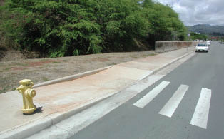 The parallel curb ramp shown was placed into a sidewalk/roadway with an existing grade of approximately 4%. The design thus called for a longer uphill ramp run from the central landing than required for the downhill ramp run to achieve acceptable ramp slopes.
- Both ramp runs slope at 8.3% maximum. On a steeper roadway, it may be necessary to limit the longer ramp run to avoid ‘chasing grade' indefinitely. PROWAAC suggests 15 feet as a practical limit.
- Still needed: detectable warnings
MODEL SIDEWALKS
15- to 20-foot Curb to Right-of-Way Line

1. PAR (Pedestrian Access Route)
- 4-foot-wide minimum, 5-foot width recommended.
- Set PAR back from curb to allow for street furnishings and pedestrian comfort.
- Set PAR back from building face/right-of-way line.
2. Utility Pole/Street Light
- Locate between curb and improved area, well outside PAR.
- Locate outside the recommended horizontal clearance to obstructions, 18 inches from face of curb minimum.
3. Utility Meter/Underground Vault/Manhole
- Locate outside PAR in furniture or frontage zones.
- Grates and covers should comply with surface characteristics guidelines if located within the pedestrian circulation path.
4. Hatch (At-grade Access Door for Deliveries and Access to Building)
- Locate between PAR and building in frontage zone.
5. Fire Hydrant
- Locate outside PAR, typically in furnishing zone.
6. Accessible Parallel Parking
- Locate in most level area of block (recommended practice) to maximize usability.
- Provide 8 feet of space with 5-foot minimum obstruction-free access aisle adjacent to space for parallel parking.
- Curb line shifts toward right-of-way to accommodate access aisle.
- Space and access aisle should have smooth surface for lift deployment. Minimize cross slope for lift operation.
7. Parking Meter for Accessible Space
- Locate at head of space or other nearby area with accessible connection to PAR and access aisle.
- Instructions visible from 40-inch height at center of clear approach area.
- Coin drop at 48-inch maximum height.
8. Clear Approach Area
- Minimum 30-inch by 48-inch obstruction-free
area centered on object being used (e.g. meter, phone).
- Slope area less than 2% in all directions.
- Space should be firm, stable, and slip-resistant.
9. Curb Ramp
- 4-foot-wide (minimum) ramp.
- 1:12 maximum grade on ramp.
- Connect to PAR and to access aisle.
- Provide side flare at 1:10 maximum on both sides of curb ramp where adjacent to improved surface. A returned curb can be used where the curb ramp is adjacent to landscaping other than non-walking surface. No detectable warning is used where ramp connects PAR to an access aisle or other non-vehicular surface.
- Landing can overlap PAR.
10. Driveway
- Maintain PAR elevation across driveway.
- Provide good visibility and sight distance for pedestrians and vehicles.
- Detectable warnings at the pedestrian crossing should be provided only if driveway or alley is signalized.
11. Tree
- Avoid species known to produce surface roots, which may buckle sidewalk.
- Keep tree grates clear of PAR.
- Trim low hanging limbs to avoid creating protruding objects (hazardous especially to visually impaired pedestrians). Use species that do not obstruct sightlines for pedestrians and vehicle operators.
12. Bus Stop and Shelter
- Provide bus boarding and alighting area 5-feet-wide by 8-feet-deep (minimum from curb) for lift deployment.
- Connect waiting and boarding areas to PAR.
- If there is a bench, provide a 30-inch by 48-inch clear approach area adjacent to the bench and connected to bus boarding and alighting area.
- Keep signage from protruding into clear approach areas and/or PAR.
- Provide raised and Braille characters for route identification only (schedules, timetables, and maps are not required to have raised and Braille characters).
- For all signage (including schedules, timetables and maps) comply with current ADAAG for finish and contrast, case, style, character proportions and spacing, and stroke thickness.
13. Landscaping
- Maintain appropriate sight distances. Use low ground cover and similar plantings so as to not obstruct sightlines for pedestrians and vehicle operators.
14. Sidewalk Furnishings, Trash Receptacle, and Similar Items
- Locate outside PAR.
- 30-inch by 48-inch clear approach area adjacent to benches and tables connected to the PAR.
- Trash receptacle openings within reach range requirements.
15. Telephone
- 30-inch by 48-inch clear approach area that may overlap with other clear spaces.
- Provide phone that complies with TTY and is accessible to wheelchair users.
16. Bike Rack
- Locate outside PAR.
- Orient so bikes on rack are not encroaching on PAR.
MODEL SIDEWALKS
12-foot Curb to Right-of-Way Line

1. PAR (Pedestrian Access Route)
- 4-foot-wide minimum, 5-foot width recommended.
- Set PAR back from curb to allow for street furnishings and pedestrian comfort.
- PAR is adjacent to the building face/right-of-way line (no frontage zone).
2. Utility Pole/Street Light
- Locate between curb and improved area, well outside PAR.
- Locate outside the recommended horizontal clearance to obstructions, 18 inches from face of curb minimum.
3. Utility Meter/Underground Vault/Manhole
- Locate outside PAR in furniture or frontage zones.
- Grates and covers should comply with surface characteristics guidelines if located with pedestrian circulation path.
4. Hatch (At-grade Access Door for Deliveries and Access to Building)
- Offset PAR as needed to provide minimum 4-foot path around the hatch.
5. Fire Hydrant
- Locate outside PAR, typically in furnishing zone.
6. Accessible Parallel Parking
- Locate in most level area of block (recommended practice) to maximize usability.
- Provide 8 feet of space with 5-foot minimum obstruction-free access aisle adjacent to space for parallel parking.
- Curb line shifts toward right-of-way to accommodate access aisle.
- Space and access aisle should have smooth surface for lift deployment. Minimize cross slope for lift operation.
7. Parking Meter for Accessible Space
- Locate at head of space or other nearby area with accessible connection to PAR and access aisle.
- Instructions visible from 40-inch height at center of clear approach area.
- Coin drop at 48-inch maximum height.
8. Clear Approach Area
- Minimum 30-inch by 48-inch obstruction-free area centered on object being used (e.g. meter, phone).
- Slope area less than 2% in all directions.
- Space should be firm, stable, and slip-resistant.
9. Curb Ramp
- 4-foot-wide (minimum) ramp.
- 1:12 maximum grade on ramp.
- Connect to PAR and to access aisle.
- Parallel-type ramps required due to limited available right-of-way width.
- Landing can overlap PAR.
10. Driveway
- Maintain PAR elevation across driveway.
- Provide good visibility and sight distance for pedestrians and vehicles.
- Detectable warnings should be provided only if driveway or alley is signalized.
11. Tree
- Avoid species known to produce surface roots, which may buckle sidewalk.
- Keep tree grates clear of PAR.
- Trim low hanging limbs to avoid creating protruding objects (hazardous especially to visually impaired pedestrians). Use species that do not obstruct sightlines for pedestrians and vehicle operators.
12. Bus Stop and Shelter
- Provide bus boarding and alighting area 5-feet-wide by 8-feet-deep (minimum from curb) for lift deployment.
- Connect waiting and boarding areas to PAR.
- If there is a bench, provide a 30-inch by 48-inch clear approach area adjacent to the bench and connected to bus boarding and alighting area.
- Keep signage from protruding into clear approach areas and/or PAR.
- Provide raised and Braille characters for route identification only (schedules, timetables, and maps are not required to have raised and Braille characters).
- For all signage (including schedules, timetables and maps) comply with current ADAAG for finish and contrast, case, style, character proportions and spacing, and stroke thickness.
13. Landscaping
- Maintain appropriate sight distances. Use low ground cover and similar plantings so as to not obstruct sightlines for pedestrians and vehicle operators.
14. Sidewalk Furnishings, Trash Receptacle, and Similar Items
- Locate outside PAR.
- 30-inch by 48-inch clear approach area adjacent to benches and tables connected to the PAR.
- Trash receptacle openings within reach range requirements.
15. Telephone
- 30-inch by 48-inch clear approach area that may overlap with other clear spaces.
- Provide phone that complies with TTY and is accessible to wheelchair users.
16. Bike Rack
- Locate outside PAR.
- Orient so bikes on rack are not encroaching on PAR.
MODEL SIDEWALKS
8- to 9-foot Curb to Right-of-Way Line

1. PAR (Pedestrian Access Route)
- 4-foot-wide minimum, 5-foot-width recommended.
- Set PAR back from curb to allow for street furnishings and pedestrian comfort.
- PAR is adjacent to the building face/right-of-way line (no frontage zone).
2. Utility Pole/Street Light
- Locate between curb and improved area, well outside PAR.
- Locate outside the recommended horizontal clearance to obstructions, 18 inches from face of curb minimum.
3. Utility Meter/Underground Vault/Manhole
- Locate outside PAR in furniture or frontage zones wherever possible.
- When in the sidewalk area, grates, and covers should have firm, stable, and slip resistant covers that are free from level changes.
4. Hatch (At-grade Access Door for Deliveries and Access to Building)
- Offset PAR as needed to provide minimum 4-foot clear path around the hatch.
5. Fire Hydrant
- Locate outside PAR, typically in furnishing zone.
6. Accessible Parallel Parking
- Locate in most level area of block (recommended practice) to maximize usability.
- Provide 8 feet of space with 5-foot minimum obstruction-free access aisle adjacent to space for parallel parking.
- Sidewalk width narrows toward right-of-way to accommodate access aisle.
- Space and access aisle should have smooth surface for lift deployment. Minimize cross slope for lift operation.
7. Parking Meter for Accessible Space
- Locate at head of space or other nearby area with accessible connection to PAR and access aisle.
- Instructions visible from 40-inch height at center of clear approach area.
- Coin drop at 48-inch maximum height.
8. Clear Approach Area
- Minimum 30-inch by 48-inch obstruction free area centered on object being used (e.g. meter, phone).
- Slope area less than 2% in all directions.
- Space should be firm, stable, and slip-resistant.
9. Curb Ramp
- 4-foot wide (minimum) ramp.
- 1:12 maximum grade on ramp.
- Connect to PAR and to access aisle.
- Parallel type curb ramps required due to limited available right-of-way width.
- Landing can overlap PAR.
10. Driveway
- Maintain PAR elevation across driveway.
- To maintain less than 2% cross slope on the PAR, the ramped vehicular entry into the driveway must be split into two sections. Some of the required rise is accommodated between the curb line and the edge of the PAR; the balance is located on far side (non-street side) of the PAR. For the purposes of this illustration, it is assumed that the PAR can meet this elevation without adding curb ramps. If this is not possible, a solution similar to that shown in the 4- to 5-foot sidewalk model would be required.
- Provide good visibility and sight distance for pedestrians and vehicles.
- Detectable warnings should be provided only if driveway or alley is signalized.
11. Tree
- Avoid species known to produce surface roots, which may buckle sidewalk.
- Keep tree grates clear of PAR.
- Trim low hanging limbs to avoid creating protruding objects (hazardous especially to visually impaired pedestrians). Use species that do not obstruct sightlines for pedestrians and vehicle operators.
12. Bus Stop (No Shelter)
- Provide bus boarding and alighting area 5-feet wide by 8-foot deep (minimum from curb) for lift deployment.
- Connect waiting and boarding areas to PAR.
- If there is a bench, provide a 30-inch by 48-inch clear approach area adjacent to the bench and connected to bus boarding and alighting area.
- Keep signage from protruding into clear approach areas and/or PAR.
- Provide raised and Braille characters for route identification only (schedules, timetables, and maps are not required to have raised and Braille characters).
13. Landscaping
- Maintain appropriate sight distances. Use low ground cover and similar plantings so as to not obstruct sightlines for pedestrians and vehicle operators.
14. Sidewalk Furnishings, Trash Receptacle, and Similar Items
- Locate outside PAR.
- 30-inch by 48-inch clear approach area adjacent to furnishings.
- Trash receptacle openings within reach range requirements.
15. Telephone
- 30-inch by 48-inch clear approach area that may overlap with other clear spaces.
- Provide phone that complies with TTY and is accessible to wheelchair users.
Items Not Accommodated at this Width:
16. Bike Rack
MODEL SIDEWALKS
4- to 5-foot Curb to Right-of-Way Line

1. PAR (Pedestrian Access Route)
- 4-feet-wide minimum, 5-foot width recommended. If the PAR is reduced to 4-foot width, a passing space must be provided at a maximum of 200-foot intervals. Passing spaces can be located in bulbouts, recaptured landscaping areas, widened sidewalks, and other similar areas.
- No frontage or furnishing zone is provided.
2. Utility Pole/Street Light
- Locate outside PAR. Maintain minimum 4-foot-wide PAR.
- Locate as close to right-of-way as possible (outside recommended horizontal clearance to obstructions and with minimum impact on the PAR). An absolute minimum of 32-inch clear width is needed for passage around the obstacle.
3. Utility Meter/Underground Vault/Manhole
- Locate outside PAR wherever possible.
- When in the sidewalk area, grates and covers should have firm, stable, and slip resistant covers that are free from level changes.
4. Hatch (At-grade Access Door for Deliveries and Access to Building)
- When in the sidewalk area, covers should have firm, stable, and slip resistant covers that are free from level changes. This includes edges and hardware.
5. Fire Hydrant
- Locate outside PAR if possible or provide at
least 32 inches of clear width for passage around the hydrant.
6. Accessible Parallel Parking
- Locate in most level area of block (recommended practice) to maximize usability.
- Provide 8-foot space with 5-foot minimum obstruction-free access aisle adjacent to space for parallel parking.
- PAR ramps down to parking level in order to provide sufficient width for space.
- Space and access aisle should have smooth surface for lift deployment. Minimize cross slope for lift operation.
7. Parking Meter for Accessible Space
- Locate at nearby area with accessible connection to PAR and access aisle.
- Instructions visible from 40-inch height at center of clear approach area.
- Coin drop at 48-inch maximum height.
8. Clear Approach Area
- Minimum 30-inch by 48-inch obstruction-free area centered on object being used (e.g. meter, phone).
- Slope area less than 2% in all directions.
- Space should be firm, stable, and slip-resistant.
9. Curb Ramp
- 4-foot-wide (minimum) ramp.
- 1:12 maximum grade on ramp.
- Connect to PAR and to access aisle.
- Parallel-type ramps required due to limited available right-of-way width.
10. Driveway
- Maintain street elevation across the driveway width where PAR crosses. The PAR must ramp down to the street elevation in order to maintain less than 2% cross slope.
- Provide good visibility and sight distance for pedestrians and vehicles.
- Detectable warnings should be provided only if driveway or alley is signalized.
11. Tree
- Avoid species known to produce surface roots, which may buckle sidewalk.
- Keep tree grates clear of PAR.
- Trim low hanging limbs to avoid creating protruding objects (hazardous especially to visually impaired pedestrians). Use species that do not obstruct sightlines for pedestrians and vehicle operators.
Items Not Accommodated at this Width:
12. Bus Stop
- No adequate space is available for lift deployment. If a bus stop must be located in an area where sidewalks are this narrow, the stop should be located at a curb ramp and no parking zone where the lift can be safely deployed and passengers can access the PAR immediately. Keep signage from protruding into clear approach areas and/or PAR.
- Provide raised and Braille characters for route identification only (schedules, timetables, and maps are not required to have raised and Braille characters).
13. Landscaping
14. Sidewalk Furnishings, Trash Receptacle, and Similar Items
15. Telephone
16. Bike Rack
CHAPTER 6: CURB RAMP EXAMPLES
by Lee R. Kenderdine, Metropolitan Government of Nashville and Davidson County, Tennessee; Janet Barlow, Accessible Design for the Blind; Laurie Kozisek, PE, City of Anchorage and Alaska Department of Transportation; and Chuck Yancey, Metropolitan Government of Nashville and Davidson County, Tennessee
Introduction
When engineers and architects work on a project that includes alterations within the rights-of-way, the construction of the curb ramps will require thought and planning. There is no standard layout for a curb ramp—each and every curb ramp is unique. The curb ramp must be designed to meet the existing topographical and physical constraints, and the requirements for curb ramp slope, cross slope, landings, and connection to the street.
Several factors need to be achieved to construct a curb ramp that will be usable by ALL pedestrians. For perpendicular curb ramps, the ramp slope must be perpendicular to the grade break at the gutter line. The curb ramp landing and gutter connection need to be designed and constructed so water does not pond at the base of the ramp or on the landing and debris does not accumulate. Debris and water reduce the usability of a curb ramp. The ramp and the landing need to be wide enough to be used by all users of the sidewalk system. If at all possible, the curb ramp slope needs to be aligned with the sidewalk and crosswalk to provide an additional cue to assist the visually impaired and blind persons in aligning to cross the street. Paired curb ramps on a corner allow better alignment for people using mobility aids and for pedestrians with vision impairments and make it easier to separate the APS.
This chapter provides examples of curb ramp designs that may be useful on 10 foot radius curb returns and 30 foot curb returns. In addition to topographical issues, width of the sidewalk and the distance between the sidewalk and curb can affect curb ramp design. Variations of these factors are also shown in the examples.
10-foot Radius Curb Returns
Example 1—Parallel Curb Ramp

Parallel Curb Ramp—5-foot sidewalk on tangents
- Provides usable curb ramps where narrow (4-5‘) sidewalk is at back of curb.
- The use of parallel curb ramps will assist the designer to construct curb ramps where the intersecting streets have considerable grade differences.
- Landing at gutter elevation increases possibility of ponding and accumulation of debris on the landing.
- Layout enables area between the two curb ramps to retain some of the curb height, which assists in drainage and discourages vehicles cutting across the corner. The use of parallel curb ramps require the sidewalk to be raised/lowered to the landing. This will cause the pedestrians using the sidewalk system to go up and down several times when going through the area of the two curb ramps.
- APS push button locator tone will assist blind or visually impaired persons in finding crossing location and the tactile arrow may provide some assistance with aligning to cross.
- The use of paired curb ramps (a separate curb ramp and landing for each direction of crosswalk) will allow pedestrians with disabilities to be aligned with the crossing direction while waiting to cross the street.
- Paired curb ramps help meet the separation requirements for APS.
Example 2—Parallel Curb Ramp, Large Shared Landing

Blended Transition Curb Ramp—5-foot sidewalk on fan
- Provides usable curb ramps where narrow (4-5‘) sidewalk is at back of curb.
- Layout moves the crosswalk closer to the intersection.
- Landing at gutter elevation increases potential for ponding and accumulation of debris on the landing.
- Slope of parallel curb ramps in sidewalk may provide a directional cue to pedestrians who are visually impaired or blind.
- APS push button locator tone will assist blind or visually impaired persons in finding crossing location and and tactile arrow may provide some assistance with aligning to cross.
- If landing is small, it may eliminate the ability to separate the APS push buttons and speakers by more than 10 feet. If APS pairs are closer than 10 feet, speech walk messages and additional features are needed to clarify walk indication.
Example 3—Perpendicular Curb Ramp

Perpendicular Curb Ramp—5-foot sidewalk on tangents
- Provides usable curb ramps where narrow (4-5‘) sidewalk is at back of curb, if additional right-of-way is available.
- This design will require the use of additional/available right-of-way.
- Layout enables area between the two curb ramps to retain the curb height, which assists in drainage and discourages vehicles cutting across the corner.
- Curb ramp must lie entirely within the crosswalk limits; flares are not part of PAR and can lie outside crosswalk markings.
- Curb ramp slope aligned with crosswalk direction will provide a directional cue for the visually impaired and blind pedestrians, particularly when combined with tactile arrow of APS.
- The use of paired curb ramps (a separate curb ramp and landing for each direction of crosswalk) will allow pedestrians with disabilities to be aligned with the crossing direction while waiting to cross the street.
- Paired curb ramps will help meet the separation requirements for APS.
- APS push button locator tones will assist blind or visually impaired persons in finding crossing location and tactile arrows may provide some assistance with aligning to cross.
Example 4—Perpendicular Curb Ramp

Perpendicular Curb Ramp—12-foot sidewalk on tangents
- 12-foot sidewalk at back of curb provides more room for directional curb ramps.
- Layout enables area between the two curb ramps to retain the curb height, which assists in drainage and discourages vehicles cutting across the corner.
- Curb ramp must lie entirely within the crosswalk limits; flares are not part of PAR and can lie outside crosswalk markings.
- Curb ramp slope aligned with crosswalk direction will provide directional cue for the visually impaired and blind, particularly when combined with tactile arrow of APS.
- Paired curb ramps will help to meet the separation requirements for APS.
- APS push button locator tones will assist blind or visually impaired persons in finding crossing location and tactile arrow may provide some assistance with aligning to cross.
Example 5—Combination Parallel and Perpendicular Curb Ramps

Combination Curb Ramp—6-foot parkway with 6-foot sidewalk on curve
- 6-foot grass area or furnishing zone between curb and PAR provides additional space for perpendicular curb ramps.
- Combination of parallel and perpendicular curb ramps will allow designers to adjust the elevation of the sidewalk to meet the landing. This may be required by constraints behind the sidewalk.
- Layout enables area between the two curb ramps to retain some of the curb height, which assists in drainage and discourages vehicles cutting across the corner.
- Curb ramp slope in line with sidewalk and crosswalks, and edge of landscaping aligned with crosswalk provides excellent direction cues to pedestrians who are blind or visually impaired.
- Paired curb ramps will help meet the separation requirements for APS.
- APS push button locator tone and tactile arrow will assist blind or visually impaired persons in finding crossing location and may provide some assistance with aligning to cross.
Example 6—Perpendicular Curb Ramps

Perpendicular Curb Ramp—6-foot parkway with 6-foot sidewalk on curve
- 6-foot grass area or furnishing zone between curb and PAR provides additional space for directional perpendicular curb ramps.
- Layout enables area between the two curb ramps to retain majority of the curb height which assists in drainage and discourages vehicles cutting across the corner.
- Curb ramp slope aligned with crosswalk direction will provide directional cue for the visually impaired and blind pedestrians, particularly when combined with tactile arrow of APS.
- Paired curb ramps will help meet the separation requirements for APS.
- APS push button locator tone will assist blind or visually impaired persons in finding crossing location and tactile arrow may provide some assistance with aligning to cross.
Example 7—Combination Parallel and Perpendicular Curb Ramps
(slope in sidewalk approach and curb ramp perpendicular to the street)

Combination Curb Ramp—8-foot parkway with 5-foot sidewalk on curve
- Grass area or furnishing zone between curb and PAR allows room for perpendicular curb ramps.
- Parallel ramps in sidewalk allow designer to adjust the elevation of the sidewalk to meet the landing. This may assist in areas where there are constraints behind the sidewalk.
- Layout enables area between the two curb ramps to retain most of the curb height, which assists in drainage and discourages vehicles cutting across the corner.
- Curb ramps in line with sidewalk and crosswalks, and edge of landscaping aligned with direction of travel on the crosswalk provide excellent direction cues to pedestrians who are blind or visually impaired.
- Care must be taken to keep APS push buttons at the edge of the parkway and close enough to the landing so they are within the reach range.
- In this example, closeness of the APS to each other will require the use of speech walk messages and additional features to clarify walk indication. If curb ramps are moved further from the corner apex, so the APS are more than 10 feet apart, speech walk messages and additional features will not be necessary.
Example 8—Perpendicular Curb Ramps

Perpendicular Curb Ramp—8-foot parkway with 5-foot sidewalk on curve
- 8-foot grass area or furnishing zone between curb and PAR allows adequate room for directional perpendicular curb ramps.
- Layout enables area between the two curb ramps to retain the curb height, which assists in drainage and discourages vehicles cutting across the corner.
- Curb ramp slope in line with sidewalk and crosswalks, and edge of landscaping aligned with crosswalk provides excellent directional cues to pedestrians who are blind or visually impaired.
- The use of directional curb ramps will allow pedestrians with disabilities to be aligned with the crossing while waiting to cross the street and when entering the street.
- Paired curb ramps will help meet the separation requirements for APS.
- In this example, the APS pair are closer than 10 feet, thus requiring the use of speech walk messages and additional features to clarify walk indication. If landing area is enlarged and ramps are moved to the outside edge of the crosswalks, this may not be necessary.
- APS push button locator tones will assist blind or visually impaired persons in finding crossing location and tactile arrows may provide some assistance with aligning to cross.
30-foot Radius Curb Returns
Example 9—Parallel Curb Ramps
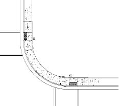
Parallel Curb Ramp—5-foot sidewalk on tangents
- Provides usable curb ramps where narrow (4-5‘) sidewalk is at back of curb.
- The use of parallel curb ramps will assist the designer to construct curb ramps where the intersecting streets have considerable grade differences.
- Landing at gutter height with less than 2% slope increases potential for ponding and accumulation of debris on the landing.
- Layout enables area between the two curb ramps to retain some of the curb height, which discourages vehicles cutting across the corner.
- The use of a parallel curb ramp will require that the sidewalk be sloped to the landing. This will cause the pedestrians using the sidewalk system to go up and down several times when going through the area of the two curb ramps.
- Crosswalk set back from intersection, but crosswalk distance is shorter due to location away from apex.
- Level landing at crosswalk location may provide a directional cue for the visually impaired and blind persons, particularly when combined with tactile arrow of APS.
- APS push button locator tone will assist blind or visually impaired persons in finding crossing location and the tactile arrow may provide some assistance with aligning to cross.
- The use of paired curb ramps (a separate curb ramp and landing for each direction of crosswalk) will allow pedestrians with disabilities to be aligned with the crossing direction while waiting to cross the street.
- Paired curb ramps help assist to meet the separation requirements for APS.
Example 10—Parallel Curb Ramps
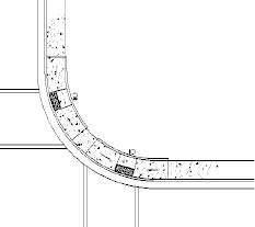
Parallel Curb Ramp—5-foot sidewalk on curve
- Provides usable curb ramps where narrow (4-5‘) sidewalk is at back of curb.
- Landing at gutter height with less than 2% slope increases possibility of drainage problems, ponding, and accumulation of debris on the landing.
- The use of parallel curb ramps will assist the designer to construct curb ramps where the intersecting streets have considerable grade differences.
- Layout enables area between the two curb ramps to retain some of the curb height, which assists in drainage and discourages vehicles cutting across the corner.
- The use of a parallel curb ramp will require that the sidewalk be sloped to the landing. This will cause the pedestrians using the sidewalk system to go up and down several times when going through the area of the two curb ramps.
- Curb ramps that do not align with the direction of travel on the crosswalk direct visually impaired and blind pedestrians toward the center of the intersection and wheelchair users have to make a directional adjustment in the roadway.
- Layout moves the crosswalks closer to the intersection.
- Paired curb ramps will help meet the separation requirements for APS.
- APS push button locator tones will assist blind or visually impaired persons in finding crossing location and tactile arrows may provide some assistance with aligning to cross. Care must be taken to keep APS push buttons close enough to the landing so they are within the reach range. Tactile arrows should be aligned with direction of travel on the crosswalk.
Example 11—Parallel Curb Ramps, Shared Landing
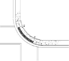
Parallel Curb Ramp, One Direction—5-foot sidewalk
(single shared curb ramp is less desirable than paired ramp)
- Provides usable curb ramps where narrow (4-5‘) sidewalk is at back of curb.
- The use of parallel curb ramps will assist the designer to construct curb ramps where the intersecting streets have considerable grade differences.
- Layout moves the crosswalk closer to the intersection.
- Landing at gutter height with less than 2% slope increases possibility of drainage problems, ponding, and accumulation of debris on the landing.
- Parallel ramps and shared landing don't provide a directional cue for pedestrians who are visually impaired or blind.
- Curb ramps that do not align with the direction of travel on the crosswalk direct visually impaired and blind pedestrians toward the center of the intersection and the wheelchair users have to make a directional adjustment in the roadway.
- APS push buttons at each end of the landing will generally be more than 10 feet apart and meet separation requirements. If APS are closer than 10 feet to each other, speech walk messages and additional features will be needed to clarify walk indication. Tactile arrows should be aligned with direction of travel on the crosswalk.
Example 12—Parallel Ramps, One Shared Landing
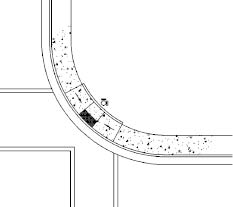
Perpendicular Curb Ramp—8-foot parkway with 5-foot sidewalk on curve
- Do not use this design unless constraints, such as drainage structures, vaults, etc. require it; paired ramps are always preferred.
- Provides usable curb ramps where narrow (4-5‘) sidewalk is at back of curb.
- Landing at gutter elevation increases possibility of drainage problems, ponding, and accumulation of debris on the landing.
- Location of landing moves the crosswalk closer to the intersection.
- Landing location requires that wheelchair users enter street at an angle, then turn in crosswalk direction.
- 4-foot by 4-foot maneuvering area required in street where crosswalks meet.
- Single shared landing eliminates the ability to separate the APS push buttons on two poles. Will require the use of speech walk messages and additional features to clarify walk indication.
Example 13—Perpendicular Curb Ramps

Perpendicular Curb Ramp—12-foot sidewalk on tangents
- 12-foot sidewalk at back of curb provides more room for directional curb ramps.
- Crosswalks are a greater distance from intersection, but crosswalk distance is shorter due to location away from apex.
- Curb ramp must lie entirely within the crosswalk limits; flares are not part of PAR and can lie outside crosswalk markings.
- Layout enables area between the two curb ramps to retain curb height; assists in drainage and discourages vehicles cutting across the corner.
- Curb ramp slope aligned with crosswalk direction will provide directional cue for the visually impaired and blind, particularly when combined with tactile arrow of APS.
- Paired curb ramps will help meet the separation requirements for APS.
- APS push button locator tones will assist blind or visually impaired persons in finding crossing location and tactile arrow may provide some assistance with aligning to cross.
Example 14—Perpendicular Curb Ramps

Perpendicular Curb Ramp—12- foot sidewalk on curve
- 12-foot sidewalk at back of curb provides more room for directional curb ramps.
- May be necessary to move curb ramps close to the apex, as shown here, due to the grades of the two cross streets or crosswalk location.
- This design moves the crosswalk closer to the intersection.
- Curb ramp must lie entirely within the crosswalk limits; flares are not part of PAR and can lie outside crosswalk markings.
- Curb ramps that do not align with the direction of travel on the crosswalk direct visually impaired and blind pedestrians toward the center of the intersection and wheelchair users have to make a directional adjustment in the roadway.
- Curb ramp and landing locations allow separation of APS push buttons and sounds by more than
10 feet.
- APS push button locator tones will assist blind or visually impaired persons in finding crossing location and tactile arrow may provide some assistance with aligning to cross. Tactile arrow should be aligned with direction of travel on the crosswalk.
Example 15—Perpendicular Curb Ramps

Perpendicular Curb Ramp—12-foot sidewalk on fan)
- No separation of 12-foot sidewalk with curb.
- Possible use due to the grades of the two cross streets.
- Moves the crosswalk closer to the intersection.
- Single curb ramp as shown may increase possibility of drainage problems.
- Ramps that do not align with the direction of travel on the crosswalk direct visually impaired and blind pedestrians toward the center of the intersection and wheelchair users have to make a directional adjustment in the roadway.
- Lack of curb at apex of curb return radius eliminates curb protection for pedestrians from vehicles cutting the corner.
- APS push buttons at each end of the landing will generally be more than 10 feet apart and meet separation requirements. If APS are closer than 10 feet to each other, speech walk messages and additional features will be needed to clarify walk indication. Tactile arrows should be aligned with direction of travel on the crosswalk.
Example 16—One Perpendicular Curb Ramp
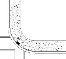
Perpendicular Curb Ramp, One Direction—12-foot sidewalk
(single shared curb ramp is less desirable than paired ramp)
- Do not use this design unless constraints, such as drainage structures, vaults, etc. require it.
- No separation of 12-foot sidewalk with curb.
- Sidewalk elevation stays the same for pedestrians traveling around the corner.
- Moves the crosswalk closer to the intersection.
- Ramps that do not align with the direction of travel on the crosswalk direct visually impaired and blind pedestrians toward the center of the intersection and wheelchair users have to make a directional adjustment in the roadway.
- Single shared landing eliminates the ability to separate the APS push buttons on two poles. Will require the use of speech walk messages and additional features to clarify walk indication.
Example 17—One Perpendicular Curb Ramp

Perpendicular Curb Ramp, One Direction—12-foot sidewalk
(single shared curb ramp is less desirable than paired ramp)
- Do not use this design unless constraints, such as drainage structures, vaults, etc. require it; paired ramps are always preferred.
- 12-foot sidewalk at back of curb.
- Curb ramps that do not align with the direction of travel on the crosswalk direct visually impaired and blind pedestrians toward the center of the intersection and wheelchair users have to make a directional adjustment in the roadway.
- Design moves the crosswalk closer to the intersection, but landing is needed at the base of the ramp, outside the travel lanes.
- Where curb ramps are the sole connection to the street, designers should consider providing wider curb ramps where pedestrian volumes are high.
- 4-foot by 4-foot maneuvering area required in street where crosswalks meet.
- APS push buttons and speakers are located in line with crosswalk lines with more than 10 feet of required separation. Level landing is needed beside the push buttons, as well as at the top of the ramp. Tactile arrows on APS should be aligned with the direction of travel on the crosswalk.
Example 18—Perpendicular Curb Ramp

Perpendicular Curb Ramp—6-foot parkway with 6-foot sidewalk on tangents
- 6-foot grass area or furnishing zone between curb and PAR.
- Sidewalk elevation stays the same for pedestrians traveling around the corner.
- Crosswalks are a greater distance from intersection.
- Landscaping layout enables area between the two curb ramps to retain majority of the curb height, which assists in drainage and discourages vehicles cutting across the corner.
- Curb ramp slope aligned with crosswalk direction will provide directional cue for the visually impaired and blind, particularly when combined with tactile arrow of APS.
- The use of paired curb ramps will allow pedestrians with disabilities to be aligned with the crossing while waiting to cross the street.
- Paired curb ramps will help meet the separation requirements for APS. Care must be taken to
keep APS push buttons close enough to the landing and edge of landscaping so they are
within the reach range.
Example 19—Perpendicular Curb Ramp

Perpendicular Curb Ramp—6-foot parkway with 6-foot sidewalk on curve
- 6-foot grass area or furnishing zone between curb and PAR.
- Landscaping enables area between the two curb ramps to retain the curb height, which assists in drainage and discourages vehicles cutting across the corner.
- Layout moves the crosswalks closer to the intersection.
- Landscaping edge aligned with the direction of travel on the crosswalk and tactile arrow on APS can provide a directional cue for the visually impaired and blind persons.
- Curb ramps that do not align with the direction of travel on the crosswalk direct visually impaired and blind pedestrians toward the center of the intersection and the wheelchair users have to make a directional adjustment in the roadway.
- In this example, APS are more than 10 feet apart. If curb ramps and landings are moved closer to the corner that separation distance may not be met and APS will require the use of speech walk messages and additional features to clarify walk indication.
- Tactile arrows should be aligned with direction of travel on the crosswalk.
Example 20—Combination Parallel and Perpendicular Curb Ramps

Combination Curb Ramp—6-foot parkway with 6-foot sidewalk on tangents
- 6-foot grass area or furnishing zone between curb and PAR.
- Parallel ramps will allow designer to adjust the elevation of the sidewalk to meet the landing. This may be due to constraints behind the sidewalks.
- Layout enables area between the two curb ramps to retain curb height, which assists in drainage and discourages vehicles cutting across the corner.
- The use of a parallel curb ramp will require that the sidewalk to be sloped to the landing. This will cause the pedestrians using the sidewalk system to go up and down several times when going through the area of the two curb ramps.
- Crosswalks are a greater distance from intersection but crosswalk distance is shorter due to location away from apex.
- Curb ramp slope aligned with crosswalk direction will provide directional cue for the visually impaired and blind, particularly when combined with tactile arrow of APS.
- Paired curb ramps will help meet the separation requirements for APS.
- Care must be taken to keep APS push buttons close enough to the landing and edge of landscaping so they are within the reach range.
Example 21—Combination Parallel and Perpendicular Curb Ramps

Combination Curb Ramp—6-foot parkway with 6-foot sidewalk on curve
- 6-foot grass area or furnishing zone between curb and PAR.
- Parallel curb ramps will allow the designer to slope the sidewalk to meet the landing. This may be needed due to constraints behind the sidewalk. The use of parallel curb ramps will assist the designer to construct curb ramps where the intersecting streets have considerable grade differences.
- Layout enables area between the two curb ramps to retain curb height, which assists in drainage and discourages vehicles cutting across the corner.
- The use of a parallel curb ramp will require that the sidewalk to be raised/lowered to the landing. This will cause the pedestrians using the sidewalk system to go up and down several times when going through the area of the two curb ramps.
- Layout moves the crosswalk closer to the intersection.
- Ramps that do not align with the direction of travel on the crosswalk direct visually impaired and blind pedestrians toward the center of the intersection and wheelchair users have to make a directional adjustment in the roadway.
- Paired curb ramps will help meet the separation requirements for APS.
- Care must be taken to keep APS push buttons close enough to the landing and edge of landscaping so they are within the reach range.
Example 22—One Perpendicular Curb Ramp

Parallel Curb Ramp, One Direction—6-foot parkway with 6-foot sidewalk
(single shared curb ramp is less desirable than paired ramps)
- Do not use this design unless constraints, such as drainage structures, vaults, etc. require it; paired ramps are always preferred.
- 6-foot grass area or furnishing zone between curb and PAR.
- Curb ramps that do not align with the direction of travel on the crosswalk direct visually impaired and blind pedestrians toward the center of the intersection and wheelchair users have to make a directional adjustment in the roadway.
- Moves the crosswalk closer to the intersection, but landing is needed at the base of the curb ramp, outside the travel lanes.
- Single shared landing eliminates the ability to separate the APS push buttons on two poles. Will require the use of speech walk messages and additional features to clarify walk indication.
- Where curb ramps are the sole connection to the street, designers should consider providing wider curb ramps where pedestrian volumes are high.
- 4-foot by 4-foot maneuvering area required in street where crosswalks meet.
Example 23—Perpendicular Curb Ramps

Perpendicular Curb Ramp—8-foot parkway with 5-foot sidewalk on tangents
- 8-foot grass area or furnishing zone between curb and PAR allows for perpendicular curb ramps.
- Crosswalk is a greater distance from intersection, but crosswalk distance is shorter due to location away from apex.
- Layout enables area between the two curb ramps to retain curb height, which assists in drainage and discourages vehicles cutting across the corner.
- Curb ramp slope in line with sidewalk and crosswalks and edge of landscaping aligned with crosswalk provides excellent direction cues to pedestrians who are blind or visually impaired.
- Paired curb ramps will help meet the more than 10 foot separation requirements for APS.
- APS push button locator tone will assist blind or visually impaired persons in finding crossing location and tactile arrow may provide some assistance with aligning to cross.
Example 24—Perpendicular Curb Ramps

Perpendicular Curb Ramp—8-foot parkway with 5-foot sidewalk on curve
- 8-foot grass area or furnishing zone between curb and PAR allows room for perpendicular curb ramps.
- Location of curb ramps allows moving the crosswalk closer to the intersection.
- Landscaping around corner allows full height curb at corner.
- Landscaping edge aligned with direction of travel on the crosswalk and tactile arrow will provide directional cue for the visually impaired and blind persons.
- Curb ramps that do not align with the direction of travel on the crosswalk direct visually impaired and blind pedestrians toward the center of the intersection and wheelchair users have to make a directional adjustment in the roadway.
- Where curb ramps are the sole connection to the street, designers should consider providing wider curb ramps where pedestrian volumes are high.
- APS push button locator tones will assist blind or visually impaired persons in finding crossing location and tactile arrows may provide some assistance with aligning to cross. Tactile arrows should be aligned with direction of travel on the crosswalk.
Example 25—One Perpendicular Curb Ramp

Perpendicular Curb Ramp, One Direction–8-foot parkway with 5-foot sidewalk (single shared curb ramp is less desirable than paired ramps)
- Do not use this design unless constraints, such as drainage structures, vaults, etc. require its use; paired ramps area always preferred.
- 8-foot grass area or furnishing zone between curb and PAR.
- Moves the crosswalk closer to the intersection.
- Where curb ramps are the sole connection to the street, designers should consider providing wider curb ramps where pedestrian volumes are high.
- Curb ramps that do not align with the direction of travel on the crosswalk direct visually impaired and blind pedestrians toward the center of the intersection and wheelchair users have to make a directional adjustment in the roadway.
- Single shared landing eliminates the ability to separate the APS push buttons on two poles. Will require the use of speech walk messages and additional features to clarify walk indication.
Case Study—Linking to Shop Entrances 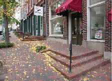
- When this sidewalk was reconstructed, new level platforms were included that link the store entrances to the sloping city sidewalk.
- This design minimizes warping of the sidewalk surface near the bottom steps so wheelchairs can stay on all four wheels when approaching the shops.
CHAPTER 7: RESOURCES
by Barbara McMillen, Pedestrian Accessibility Specialist, and others
US Department of Justice
website http://www.ada.gov/
Americans with Disabilities Act (ADA), (Pub. L. 101-336), Title II, implementing regulations for Nondiscrimination on the Basis of Disability in State and Local Government Services, 28 CFR PART 35, Final rule, which prohibits discrimination on the basis of disability by public entities. http://www.ada.gov/reg2.html
- ADA Standards for Accessible Design (1991). The ADA Standards for Accessible Design are the Access Board's 1991 ADA Accessibility Guidelines (ADAAG), adopted on July 26, 1991: http://www.ada.gov/stdspdf.htm
- Title II Technical Assistance Manual (1993) and Yearly Supplements. A 56-page manual that explains in lay terms what state and local governments must do to ensure that their services, programs, and activities are provided to the public in a nondiscriminatory manner. Many examples are provided for practical guidance: http://www.ada.gov/taman2.htm
- Title II Highlights. An 8-page outline of the key requirements of the ADA for State and local governments. This publication provides detailed information in bullet format for quick reference: http://www.ada.gov/t2hlt95.htm
- ADA Guide for Small Towns . A 21-page guide that presents an informal overview of some basic ADA requirements and provides cost-effective tips on how small towns can comply with the ADA. FAX # 3307
- The ADA and City Governments: Common Problems . A 9-page document that contains a sampling of common problems shared by city governments of all sizes, provides examples of common deficiencies and explains how these problems affect persons with disabilities.
- An ADA Guide for Local Governments: Making Community Emergency Preparedness and Response Programs Accessible to People with Disabilities. A publication that provides guidance on preparing for and carrying out emergency response programs in a manner that results in the services being accessible to people with disabilities: http://www.ada.gov/emergencyprep.htm
US Department of Justice Technical Assistance Letters . Covers state and local government's responsibilities for complying with provisions in the ADA, Title II regulations. Compliance topics:
US DOJ Settlement Agreements . Involve public rights-of-way, State of Delaware, Voluntary Agreement with terms and conditions to bring certain roads under the jurisdiction of the state into further compliance with the Americans with Disabilities Act of 1990: http://www.usdoj.gov/crt/ada/deldot.htm
Project Civic Access. A Title II compliance program that includes:
Precedent-setting Court Cases
Kinney v. Yerusalim, 9 F.3d 1067 (1993) http://www.access-board.gov/prowac/yerusalim.htm
U.S. DOJ amicus to court finding that resurfacing of city streets is an alteration requiring installation of curb ramps to comply with regulations promulgated under ADA: http://www.usdoj.gov/crt/foia/pa2.txt
Barden v. City of Sacramento, CA
On January 22, 2004, the court granted final approval of the settlement in Barden v. Sacramento. This case set a nationwide precedent requiring cities and other public entities to make all public sidewalks accessible. As a result of the court's ruling in this case, public entities must address barriers such as missing or unsafe curb cuts throughout the public sidewalk system, as well as barriers that block access along the length of the sidewalks. Following the court victory, the parties reached a settlement addressing all sidewalk barrier issues City-wide. The settlement provides that for up to 30 years, the City of Sacramento will allocate 20% of its annual Transportation Fund to make the City's pedestrian rights-of-way accessible to individuals with vision and/or mobility disabilities. This will include installation of compliant curb ramps at intersections; removal of barriers that obstruct the sidewalk, including narrow pathways, abrupt changes in level, excessive cross slopes, and overhanging obstructions; and improvements in crosswalk access. http://www.dralegal.org/downloads/cases/barden/usca_opinion.txt
- USDOJ amicus briefs filed with the courts in support of the appellants (Barden):
Metro Nashville, Davidson County, Tennessee
In January 2000, the Metropolitan Government of Nashville and Davidson County voluntarily contacted the United States Department of Justice to discuss its plans for achieving compliance with Title II of the ADA. A formal agreement was reached between the two parties in July 2000. The Final Settlement Agreement was reached in 2004. Metropolitan Government of Nashville and Davidson County has conducted extensive reviews of their policies and procedures and made substantial changes to ensure the integration of accessibility into the activities conducted in the public rights-of-ways. Processes have been developed that are transferable to any state and other local governments as models for complying with ADA obligations and regulations.
Final Settlement Agreement between the United States of America and Metropolitan Government of Nashville and Davison County Tennessee for Structural Changes to Public Buildings and Facilities: http://www.usdoj.gov/crt/ada/nashvil2.htm
Final Transition Plan For Achieving Program Access as Required by the Americans with Disabilities Act, 1990, and Section 504 of the Rehabilitation Act, 1973, as amended December 10, 2003: http://www.nashville.gov/finance/support_services/ada/doj_2047143_final_textonly.htm
Policy and procedure forms for projects in the public rights-of-way: http://www.nashville.gov/gsa/ADA/procedures-forms.htm
- Facility Construction and Rehabilitation Project Procedures for Integration of ADA Compliance Requirements, process that ensures ADA requirements are integrated in the business processes through the government, for new construction or rehabilitation of existing facilities, including recreational areas: ftp://ftp.nashville.gov/web/gsa/ADA/forms/proced_for_integ_of_ada_compl_reqs_accomp_projsubmform_pdftagged.pdf
- Project Submittal Form, requires sign-off on processes and procedures for ADA compliance in projects: ftp://ftp.nashville.gov/web/finance/support-services/ada/ProjSubmitFormRev01-22-04.pdf
- 20% Rule for Work Completed in the Public right-of-way. This policy applies 20% of the funds for any activities occurring within the right-of-way of any street, highway, or alley in Metro Nashville, Davidson County to be applied to provide pedestrian accessibility. The priority for using the 20% funds is crosswalks, sidewalk obstructions, and sidewalks. The 20% Rule excludes the cost of curb ramp installations, which are included as part of the standard project bid: ftp://ftp.nashville.gov/web/gsa/ADA/forms/20percent-row_pdftagged.pdf
- Right-of-way Accessibility Review Form, project checklist: ftp://ftp.nashville.gov/web/gsa/ADA/forms/right-of-way_rvw_pdftagged.pdf
- Technical Infeasibility Statement Form, ADAAG contains a provision relating to “technical infeasibility” applicable only in alterations (does not apply to new construction). If compliance cannot be achieved to the maximum extent feasible it must be documented and receive sign-off before proceeding with the project: ftp://ftp.nashville.gov/web/gsa/ADA/forms/tech_infeas_pdftagged.pdf
- Common ADA Errors and Omissions in New Construction and Alterations. The ADA requires that new construction and alterations to existing facilities comply with the ADA Standards for Accessible Design (Standards). This document lists a sampling of common accessibility errors or omissions that have been identified through the DOJ's ongoing enforcement efforts. ADA requirements for new construction and alterations include detailed provisions for elements, spaces, and facilities. Successful accessibility is often measured in inches, so attention to detail can make the difference between achieving access and excluding or injuring someone. When the ADA's minimum requirements are not met, the results can limit or exclude a person with a disability and can be dangerous: ftp://ftp.nashville.gov/web/gsa/ADA/forms/common_e-o_newconstr-alts_pdftagged.pdf
- Nashville-Davidson County Strategic Plan For Sidewalks & Bikeways, March 2003: http://www.nashville.gov/mpc/sidewalks/finalplan_march03.htm
- Provides and extensive discussion of pedestrian access issues in the Appendix B, Pedestrian Facilities Design Guidelines: ftp://ftp.nashville.org/web/mpc/sidewalks/Mar2003/appendix_b.pdf
US Access Board http://www.access-board.gov
Building a True Community: Final Report (January 2001), PROWAAC's report to the US Access Board: http://www.access-board.gov/prowac/commrept/index.htm
Revised Draft Guidelines for Accessible Public Rights-of-Way (HTML Version), November 23, 2005. Second draft of PROWAG—provisions specific to public rights-of-way to supplement the Board's ADA and ABA accessibility guidelines (2004). The guidelines become enforceable when they are adopted by the standard setting agencies—the DOJ and the DOT:
http://www.access-board.gov/prowac/draft.htm
Notice of availability of draft guidelines for the ADA Accessibility Guidelines for Buildings and Facilities; Architectural Barriers Act (ABA) Accessibility Guidelines; Public Rights-of-Way, Published in the Federal Register on November 23, 2005: http://www.access-board.gov/prowac/noa.htm
FHWA notice of the draft guidelines, January 23, 2006: http://www.fhwa.dot.gov/environment/bikeped/prwaa.htm
Accessible Rights-of-Way: A Design Guide . Developed by the U.S. Access Board in collaboration with the USDOT/FHWA to assist public works and transportation agencies covered by Title II of the ADA in designing and constructing public sidewalks and street crossings: http://www.access-board.gov/prowac/guide/PROWGuide.htm
Interfacing Audible Pedestrian Signals and Traffic Signal Controllers . Provides detailed APS product information specifically focused on the interfacing of APS devices and traffic signal controllers. Information on the various traffic signal controllers used today is also provided. The information is intended for traffic engineers, traffic signal technicians, and others who are implementing APS technologies: http://www.access-board.gov/research/APS/report.htm
Pedestrian Access to Modern Roundabouts . Provides research on improving accessibility of roundabouts to blind pedestrians, suggested approaches, differences in access issues between roundabouts and traditional intersections, and orientation and mobility techniques used by pedestrians who are blind in traveling independently across streets: http://www.access-board.gov/research/roundabouts/bulletin.htm
Detectable Warnings Update : http://www.access-board.gov/adaag/dws/update.htm
Detectable Warnings: Synthesis of U.S. and International Practice. This synthesis summarizes the state-of-the-art regarding the design, installation, and effectiveness of detectable warning surfaces used in the U.S. and abroad: http://www.access-board.gov/research/DWSynthesis/report.htm
Accessible Sidewalks (DVD). A four-part video developed by the Access Board to illustrate access issues and considerations; is available free from the Board on DVD. The DVD contains:
- Program 1: Pedestrians Who Use Wheelchairs
- Program 2: Pedestrians Who Have Ambulatory Impairments
- Program 3: Pedestrians Who Have Low Vision
- Program 4: Pedestrians Who Are Blind
http://www.access-board.gov/prowac/video/index.htm
Federal Highway Administration (FHWA) Bicycle and Pedestrian Program : http://www.fhwa.dot.gov/environment/bikeped/index.htm
FHWA program offices have resources that promote pedestrian transportation accessibility, use, and safety.
The Bicycle & Pedestrian Program of Office of Natural and Human Environment: http://www.fhwa.dot.gov/environment/bikeped/index.htm
FHWA POLICY MEMORANDA
The Americans with Disabilities Act Policy promotes universal design and the development of a fully accessible transportation system. This document calls for mainstreaming facilities for people with disabilities in our nation's transportation system: http://www.fhwa.dot.gov/environment/bikeped/atl.htm
Use of 2005 PROWAG draft: http://www.fhwa.dot.gov/environment/bikeped/prwaa.htm
Detectable Warnings: FHWA and the US Access Board encourage the use of the latest recommended design for truncated domes.
http://www.fhwa.dot.gov/environment/bikeped/dwm04.htm (2004)
http://www.fhwa.dot.gov/environment/bikeped /dwm.htm (2002)
The Manual on Uniform Traffic Control Devices (MUTCD). Defines the standards used by road managers nationwide to install and maintain traffic control devices (signs, signals, and markings) on all streets and highways. The MUTCD is published by the FHWA under 23 Code of Federal Regulations (CFR), Part 655, Subpart F. The MUTCD audience includes the insurance industry, law enforcement agencies, academic institutions, private industry, and construction and engineering concerns: http://mutcd.fhwa.dot.gov/kno-2003r1.htm; http://mutcd.fhwa.dot.gov/HTM/2003r1/html-index.htm
Designing Sidewalks and Trails for Access Part I of II: Review of Existing Guidelines and Practices : http://www.fhwa.dot.gov/environment/bikeped/Access-1.htm
Designing Sidewalks and Trails for Access, Part II of II: Best Practices Design Guide : http://www.fhwa.dot.gov/environment/sidewalk2/index.htm
FHWA two-part guidebook on planning and designing sidewalks and trails for access. Created to provide planners, designers, and transportation engineers with a better understanding of how sidewalks and trails should be developed to promote pedestrian access for all users, including people with disabilities.
Design Guidance Accommodating Bicycle and Pedestrian Travel: A Recommended Approach . A policy statement adopted by the United States Department of Transportation. USDOT encourages public agencies, professional associations, advocacy groups, and others to integrate bicycling and walking into the transportation mainstream: http://www.fhwa.dot.gov/environment/bikeped/Design.htm
Freedom to Travel Survey . The Bureau of Transportation Statistics (BTS),(USDOT), survey designed to identify the impact of transportation on the work and social lives of people with disabilities, and the extent to which such impact is unique to that population: http://www.bts.gov/publications/freedom_to_travel/
Safety Effects of Marked Versus Unmarked Crosswalks at Uncontrolled Locations Final Report and Recommended Guidelines . Includes recommendations on how to provide safer crossings for pedestrians: http://www.tfhrc.gov/safety/pubs/04100/index.htm
How to Develop a Pedestrian Safety Action Plan . Guide and resource for improving pedestrian safety intended to assist agencies in enhancing their existing pedestrian safety programs and activities, including identifying safety problems and selecting optimal solutions through redesign and engineering countermeasures. http://www.walkinginfo.org/pp/howtoguide2006.pdf
Accommodating Pedestrians in Work Zones . Illustrated brochure: http://safety.fhwa.dot.gov/wz/wzp3.htm
OTHER RESOURCES
Guides, Manuals, Reports, Research, Data
AASHTO guides can be purchased through the AASHTO web site at: http://www.transportation.org
- Guide for the Planning, Design and Operation of Pedestrian Facilities (2004). The American Association of State and Highway Transportation Officials (AASHTO), presents effective measures for accommodating pedestrians on public rights-of-way. The guide recognizes the profound effect that land use planning and site design have on pedestrian mobility and addresses these topics as well.
- A Policy on Geometric Design of Highways and Streets , (Green Book), AASHTO, 2001
Accessible Design for the Blind website contains information on detectable warnings and APS: http://www.accessforblind.org/
Institute of Transportation Engineers (ITE) Accessible Public Rights-of-Way: Planning and Designing for Alterations; Electronic Toolbox for Making Intersections More Accessible for Pedestrians Who Are Blind or Visually Impaired: http://www.ite.org/accessible/
The following publications can be purchased through the ITE web site at http://www.ite.org :
- Design and Safety of Pedestrian Facilities: A Proposed Recommended Practice of the Institute of Transportation Engineers , ITE Technical Council Committee 5A-5.
- Alternative Treatments for At-Grade Pedestrian Crossings , an informational report documenting studies on pedestrian crossings.
- Improving the Pedestrian Environment Through Innovative Transportation Design .
Pedestrian and Bicycle Information Center (PBIC), a clearinghouse with information on pedestrian design, planning, research, safety and education: http://www.walkinginfo.org/
American Council of the Blind (ACB) Pedestrian Safety Website , a clearinghouse with resources for pedestrian safety, wayfinding, and accessible travel: http://www.acb.org/pedestrian/index.html
- Pedestrian Safety Handbook provides resources on understanding and details for improving travel for people with visual disabilities: http://www.acb.org/pedestrian/handbook.html
- Survey of Signalized Intersection Accessibility. ACB surveyed 158 pedestrians who are legally blind regarding their experiences in independently crossing at intersections with and without audible signals.
- 91% of respondents indicated that they sometimes had difficulty knowing when to begin crossing (difficulty hearing surge of traffic on street beside them), which they attributed to one or more of four reasons.
- 79% of respondents indicated that they sometimes had difficulty traveling straight across the street, for one or more of three reasons.
- 90% of respondents had experienced one or more problems with pushbuttons.
- 71% of respondents had experienced one or more difficulties with existing accessible pedestrian signals.
http://www.acb.org/pedestrian/phd2a.html#ped09
NCHRP , an industry research program overseen by TRB
Accessible Pedestrian Signals; A Synthesis and Guide to Best Practices , NCHRP Research Project 3-62, Guidelines for Accessible Pedestrian Signals provides an introduction to APS research: http://www.walkinginfo.org/aps/home.cfm
State DOTs
Wisconsin DOT, Curb Ramp Detectable Warning Fields: Truncated Warning Dome Installations Technical Note (June 2005). Provides technical information on installations of curb ramp detectable warnings/truncated domes: http://www.dot.wisconsin.gov/library/research/docs/finalreports/tau-finalreports/warningdomestechnote.pdf
WisDOT Truncated Warning Dome Systems for Handicap Access Ramps (Nov. 2003). Product trials—A study in partnership with the FHWA and the City of Madison Engineering Division. Product trials of truncated dome warning systems for ramps to evaluate constructability, durability, aesthetics, cost, and conformance to the standard: http://www.dot.wisconsin.gov/library/research/docs/finalreports/tau-finalreports/warningdomes.pdf
Georgia DOT Pedestrian & Streetscape Guide . Provides a tool kit and technical information on “best practices” that apply to situations encountered in project development, examination of pedestrian characteristics, and other factors that influence pedestrian travel, spatial analysis, ways to prioritize projects using Geographic Information Systems (GIS), referencing the Latent Demand Model and Portland, OR's Pedestrian Potential Index: http://www.dot.state.ga.us/dot/plan-prog/planning/projects/bicycle/ped_streetscape_guide/toolkit%202%20final.pdf
Indiana DOT Standard Specifications (2006). Section 604, Sidewalks, Curb ramps, Steps and Handrails: http://www.in.gov/dot/div/contracts/standards/book/2006MasterSpecBook.pdf
Oregon DOT, Standard Drawings for Sidewalks & Ramps (Roadway 700—Curbs, Islands, Sidewalks, and Driveways): http://egov.oregon.gov/ODOT/HWY/ENGSERVICES/roadway_drawings.shtml#Roadway_700_Curbs_etc_
Washington State DOT Pedestrian Design Considerations Design Manual , May 2006. Planning, design, and operations guidance: http://www.wsdot.wa.gov/EESC/Design/DesignManual/desEnglish/1025-E.pdf
Arizona DOT Statewide Bicycle and Pedestrian Plan (2003). A guide for making pedestrian-related transportation decisions at the state and local level: http://www.azbikeped.org/statewide-bicycle-pedestrian-intro.html
Pedestrian planning, design, and operation policies: http://www.azbikeped.org/appendix%20c/08_DG.pdf
Vermont DOT Pedestrian and Bicycle Facility Planning and Design Manual , Chapter 3, Pedestrian Facilities. Provides policy, planning and design guidance for sidewalks and walkways, street corners and intersections, and street and driveway crossings: http://www.aot.state.vt.us/progdev/Documents/LTF/FinalPedestrianAndBicycleFacility/Chap3.pdf
California DOT Pedestrian and Bicycle Facilities in California , Technical Reference Report (2005). Provides guidance on policy, planning, and design: http://www.dot.ca.gov/hq/traffops/survey/pedestrian/TR_MAY0405.pdf
Colorado DOT directive for ADA Accessibility Requirements for CDOT Transportation Projects . Includes policies and procedures for pedestrian accessibility in roadway resurfacing projects: http://www.dot.state.co.us/DesignSupport/ADA/ADA%20Accessibility%20Requirements%20in%20CDOT%20Transportation%20Projects%2010-20-2003%20.pdf
Colorado DOT Standard Specifications for Detectable Warnings , Section 608, May 26, 2005 Revision: http://www.dot.state.co.us/DesignSupport/Construction/1999PSP/608dw.doc
Maryland State Highway Administration Accessibility Policy and Guidelines for Pedestrian Facilities Along State Highways: http://www.sha.state.md.us/businesswithSHA/bizstdsspecs/ohd/ada/adapolicy.asp
Training, Courses, Presentations
Accessible Sidewalks (DVD), a 4-part video developed by the Access Board to illustrate access issues and considerations, is available free from the Board on DVD. The DVD contains:
- Program 1: Pedestrians Who Use Wheelchairs
- Program 2: Pedestrians Who Have Ambulatory Impairments
- Program 3: Pedestrians Who Have Low Vision
- Program 4: Pedestrians Who Are Blind
http://www.access-board.gov/prowac/video/index.htm
Designing and Planning Accessible Pedestrian Facilities training course, developed in cooperation with FHWA and the Association of Pedestrian and Bicycle Professionals (APBP), contact: info@apbp.org
Designing Accessible Pedestrian Facilities in the Public Rights-of-Way Series. This series of four individual courses is intended to provide practicing traffic and highway engineers, planners, and transportation managers with a better understanding of the latest public rights-of-way guidelines developed by the U.S. Access Board, and how they can be applied in better designing sidewalks and intersections to accommodate persons with disabilities. Each of the four course modules is designed to be informative in the area of identifying the needs of persons with disabilities, provide practical engineering approaches to successfully addressing these needs on existing facilities, and serve as catalysts in promoting innovative solutions to similar challenges at future locations. ITE: http://www.ite.org/education/olg.asp
Michael Moule, P.E., PTOE, Livable Streets, Inc., (813) 221-5223; fax (813) 354-4422; moule@livablestreetsinc.com
Pedestrians with Vision Loss or Blindness , powerpoint presentation: http://safety.fhwa.dot.gov/intersections/roundaboutsummit/rndabtatt4.htm
Accessible Pedestrian Signal Features New Possibilities for Access in the US , Janet Barlow, Accessible Design for the Blind, powerpoint presentation: http://www.accessforblind.org/presentations/aps/Accessible_Signals_Presentation.pps
Transportation Prescription for Healthy Cities, by Ian M. Lockwood, P.E., Presentation that includes a discussion in Section 3 on how traditional language used by engineers can unknowingly contain biases; recommendations for the use of unbiased terminology. Prepared for the Robert Wood Johnson Foundation and the New Jersey Department of Transportation:
http://policy.rutgers.edu/vtc/documents/Events.ComGrnd-Lockwood_trans_perscript.pdf#search='TRANSPORTATION%20PRESCRIPTION%20FOR%20healthy%20cities%20Ian%20lockwood
Planning Agencies
Nashville-Davidson County Strategic Plan For Sidewalks & Bikeways , March 2003: http://www.nashville.gov/mpc/sidewalks/finalplan_march03.htm
Provides an extensive discussion of pedestrian access issues in Appendix B, Pedestrian Facilities Design Guidelines: ftp://ftp.nashville.org/web/mpc/sidewalks/Mar2003/appendix_b.pdf
City of Tucson Land Use Ordinance Code , Section 3.2.8 Access Provision provides design standards for pedestrian circulation paths, access to streets, and improvements for pedestrian facilities to increase public safety by lessening the conflict between vehicular and pedestrian activities: http://www.tucsonaz.gov/planning/codes/luc/lucweb/Art3div2.html#TopOfPage
San Diego, CA Pedestrian Master Plan (2004): http://www.sandag.cog.ca.us/uploads/publicationid/publicationid_713_3269.pdf
City of Sacramento Pedestrian Master Plan, Making Sacramento the Walking Capital , Public Review Draft, (November 2005): http://www.cityofsacramento.org/pedestrian_master_plan/Draft_Ped_Master_Plan_11.02.05.pdf
Pedestrian Safety Guidelines for the City of Sacramento Public Works Department Traffic Engineering Division (January 9, 2003): http://www.cityofsacramento.org/dsd/dev_eng_finance/entitlements/pdfs/Ped_Safety.pdf
Portland, OR Pedestrian Master Plan (1998): www.portlandonline.com/transportation/index.cfm?c=37064
“Portland Pedestrian Design Guide,” an element of the Pedestrian Master Plan for the City of Portland, Oregon: http://www.portlandonline.com/shared/cfm/image.cfm?id=84048
Oakland, CA Pedestrian Master Plan (Nov. 2002), Part of the Land Use and Transportation Element of the City of Oakland‘s General Plan: http://www.oaklandnet.com/government/pedestrian/PedMasterPlan.pdf
City of Cambridge, MA: Pedestrian Plan (2000): http://www.cambridgema.gov/~CDD/et/ped/plan/ped_plan.html .
City of Seattle Right-of-Way Improvements Manual provisions for incorporating pedestrian travel into the process, procedures, design criteria for grading, design cross section, intersections, driveways, curbs, sidewalks and crosswalks: http://www.seattle.gov/transportation/rowmanual/manual/
The City of Seattle Standard Plans and Standard Specifications for Road, Bridge, and Municipal Construction : http://www.seattle.gov/util/Engineering/Standard_Plans_&_Specs/index.asp
400 Street Paving & Appurtenance, includes curb ramps: http://www2.cityofseattle.net/util/standardplans/plans2005/400Series.pdf
Boulder, CO: Transportation Master Plan (2003), fully integrates pedestrian travel into the transportation plan: http://www.bouldercolorado.gov/index.php?option=com_content&task=view&id=331&Itemid=1201 .
“Chapter 6, Pedestrian Policies” includes a snow removal policy provision for pedestrian travel: http://www.ci.boulder.co.us/files/Transportation_Master_Plan/Chapter6_1.pdf
“City of Boulder Pedestrian Crossing Treatment Warrants,” provisions and criteria for improving pedestrian street crossing warrants for better access and safety compared to the MUTCD criteria: http://www.ci.boulder.co.us/files/Transportation_Master_Plan/Boulder_Ped_Xing_Warrants.pdf
Planning and Funding Accessible Pedestrian Facilities
From www.ite.org/accessible/accessibleped.asp; www.fhwa.dot.gov/environment/bikeped/bp-guid.htm
Funding Availability and Design Philosophy
The combined funding of Federal, state and local government on surface transportation is one of this country's largest domestic spending programs. The funding for pedestrian issues has increased dramatically since 1991. This increase was spurred by transportation legislation, grassroots support, and accessibility policies. Pedestrian projects and programs are eligible for funding in almost every major federal-aid surface transportation category. Transportation legislation, including the Safe, Accountable, Flexible, Efficient Transportation Equity Act: A Legacy for Users (SAFETEA-LU) calls for mainstreaming pedestrian (and bicycle) projects into planning, design, and operation of our nation's transportation system. Transportation facilities must include features that will allow people of all abilities to use them. The federal-aid highway program can work hand-in-hand with the ADA of 1990, which requires all pedestrian facilities be accessible for people with disabilities. Accessibility is not an exclusive or separate issue. Rather, accessibility design is fundamental to the walking environment because all pedestrians with or without disabilities benefit from accessibility design. Accessibility is an intrinsic part of planning, retrofitting, and constructing pedestrian facilities, along with safe accommodation and good design. Accessibility is a safety issue because if a facility is not accessible, then it is not safe for more than 54 million people in this country who have some form of disability. The USDOT's policy on accessibility states, “Accessibility is a civil right. The key function of transportation, at its most fundamental level, is to provide basic mobility to society. It is our responsibility to strive to ensure that transportation systems are not only safe and efficient, but also usable by all-including persons with disabilities.” The USDOT's Accessibility Policy Statement can be reviewed at http://www.fhwa.dot.gov/environment/bikeped/atl.htm.
Accessibility requirements are not new and these obligations have been around long before the ADA in 1990. States and localities were first required to place curb ramps at street crossings in 1973 by Section 504 of the Rehabilitation Act. Also, the DOJ has ruled that resurfacing a roadway (beyond filling pot holes) is an alteration, thus triggering the requirement to place curb ramps at roadway intersections.
Funding Sources for Pedestrian Projects
Pedestrian projects are broadly eligible for funding from almost all the major federal-aid highway, transit, safety and other programs. The matrix at the end of this section denotes the FHWA and FTA funding programs that can be used to fund pedestrian projects and activities.
Federal-Aid Highway Programs
National Highway System funds may be used to construct pedestrian walkways and facilities on land adjacent to any highway on the National Highway System, including Interstate highways.
Surface Transportation Program (STP) funds may be used for either the construction of pedestrian walkways, or nonconstruction projects (such as maps, brochures, and public service announcements) related to safety. TEA 21 adds “the modification of public sidewalks to comply with the Americans with Disabilities Act” as an activity that is specifically eligible for the use of these funds.
Ten percent of each state's annual STP funds is set-aside for Transportation Enhancement Activities (TEAs). The law provides a specific list of activities that are eligible TEAs and this includes “provision of facilities for pedestrians and bicycles, provision of safety and educational activities for pedestrians and bicyclists,” and the “preservation of abandoned railway corridors (including the conversion and use thereof for pedestrian and bicycle trails).” Another 10% of each state's STP funds is set aside for the Hazard Elimination and Railway–Highway Crossing programs, which address pedestrian safety issues. Each state is required to implement a Hazard Elimination Program to identify and correct locations that may constitute a danger to motorists, bicyclists, and pedestrians. Funds may be used for activities including a survey of hazardous locations and for projects on any publicly owned, shared-use path, pedestrian pathway or trail, or any safety-related traffic calming measure.
Congestion Mitigation and Air Quality Improvement Program funds may be used for either the construction of pedestrian walkways or nonconstruction projects (such as maps, brochures and public service announcements).
Recreational Trails Program funds may be used for all kinds of trail projects. Of the funds apportioned to a state, 30% must be used for motorized trail uses, 30% for nonmotorized trail uses and 40% for diverse trail uses (any combination).
Provisions for pedestrians are eligible under the various categories of the Federal Lands Highway Program in conjunction with roads, highways, and parkways. Priority for funding projects is determined by the appropriate Federal Land Agency or Tribal government.
National Scenic Byways Program funds may be used for “construction along a scenic byway of a facility for pedestrians.”
High-Priority Projects and Designated Transportation Enhancement Activities identified by SAFETEA-LU include numerous pedestrian, trail, and traffic calming projects in communities throughout the country.
Safe Routes to School funds are provided to the states to substantially improve the ability of primary and middle school students to walk and bicycle to school safely. The purposes of the program are:
- to enable and encourage children, including those with disabilities, to walk and bicycle to school;
- to make bicycling and walking to school a safer and more appealing transportation alternative, thereby encouraging a healthy and active lifestyle from an early age; and
- to facilitate the planning, development, and implementation of projects and activities that will improve safety and reduce traffic, fuel consumption, and air pollution in the vicinity (approximately 2 miles) of primary and middle schools (Grades K-8).
Each state administers its own program and develops its own procedures to solicit and select projects for funding. The program establishes two distinct types of funding opportunities: infrastructure projects (engineering improvements) and non-infrastructure related activities (such as education, enforcement, and encouragement programs
Federal Transit Program
Title 49 U.S.C. (as amended by SAFETEA-LU) allows the Urbanized-Area Formula Grants, Capital Investment Grants and Loans, and Formula Program for Other Than Urbanized Area transit funds to be used for improving pedestrian access to transit facilities and vehicles. Eligible activities include investments in “pedestrian and bicycle access to a mass transportation facility” that establishes or enhances coordination between mass transportation and other transportation.
SAFETEA-LU also created a Transit Enhancement Activity program with a one percent set-aside of Urbanized-Area Formula Grant funds designated for, among other things, pedestrian access and walkways.
Highway Safety Programs
Pedestrian and bicyclist safety remain priority areas for State and Community Highway Safety Grants funded by the Section 402 formula grant program. A state is eligible for these grants by submitting a performance plan (establishing goals and performance measures for improving highway safety) and a highway safety plan (describing activities to achieve those goals). Research, development, demonstrations, and training to improve highway safety (including pedestrian safety) is carried out under the Highway Safety Research and Development (Section 403) program.
Matrix of FHWA and FTA Funding Opportunities for Pedestrian Facilities
SAFETEA-LU Bicycle/Pedestrian Funding Opportunities |
|
NHA |
STP |
HEP |
RHC |
TEA |
CMAQ |
RTP |
FTA |
TE |
BRI |
402 |
PLA |
TCSP |
JOBS |
FLH |
BYW |
Bicycle and pedestrian plan |
|
* |
|
|
|
* |
|
|
|
|
|
* |
* |
|
|
|
Bicycle lanes on roadway |
* |
* |
* |
* |
* |
* |
|
* |
* |
* |
|
|
|
|
* |
* |
Paved shoulders |
* |
* |
* |
* |
* |
* |
|
|
|
* |
|
|
|
|
* |
* |
Signed bike route |
* |
* |
|
|
* |
* |
|
|
|
|
|
|
|
|
* |
* |
Shared-use path/trail |
* |
* |
|
|
* |
* |
* |
|
|
* |
|
|
|
|
* |
* |
Single track hike/bike trail |
|
|
|
|
|
|
* |
|
|
|
|
|
|
|
|
|
Spot improvement program |
|
* |
* |
|
* |
* |
|
|
|
|
|
|
|
|
|
|
Maps |
|
* |
|
|
|
* |
|
|
|
|
* |
|
|
|
|
|
Bike racks on buses |
|
* |
|
|
* |
* |
|
* |
* |
|
|
|
|
|
|
|
Bicycle parking facilities |
|
* |
|
|
* |
* |
|
* |
* |
|
|
|
|
|
|
* |
Trail/highway intersection |
* |
* |
* |
|
* |
* |
* |
|
|
|
|
|
|
|
* |
* |
Bicycle storage/service center |
|
* |
|
|
* |
* |
|
* |
* |
|
|
|
* |
* |
|
|
Sidewalks, new or retrofit |
* |
* |
* |
* |
* |
* |
|
* |
* |
* |
|
|
|
|
* |
* |
Crosswalks, new or retrofit |
* |
* |
* |
* |
* |
* |
|
* |
* |
|
|
|
|
|
* |
* |
Signal improvements |
* |
* |
* |
* |
* |
* |
|
|
|
|
|
|
|
|
|
|
Curb cuts and ramps |
* |
* |
* |
* |
* |
* |
|
|
|
|
|
|
|
|
|
|
Traffic calming |
|
* |
* |
* |
|
* |
|
|
|
|
|
|
* |
|
|
|
Coordinator position |
|
* |
|
|
|
* |
|
|
|
|
|
|
* |
|
|
|
Safety/education position |
|
* |
|
|
|
* |
|
|
|
|
* |
|
|
|
|
|
Police patrol |
|
* |
|
|
|
* |
|
|
|
|
* |
|
|
|
|
|
Helmet promotion |
|
* |
|
|
* |
|
|
|
|
|
* |
|
|
|
|
|
Safety brochure/book |
|
* |
|
|
* |
* |
|
|
|
|
* |
|
|
|
|
|
Training |
|
|
|
|
|
* |
|
|
|
|
* |
|
|
|
|
|
Key
NHS |
National Highway System |
CMAQ |
Congestion Mitigation/Air Quality Program |
TCSP |
Transportation and Community and System |
STP |
Surface Transportation Program |
FLH |
Federal Lands Highways Program |
|
Preservation Pilot Program |
HEP |
Hazard Elimination Program |
BYW |
Scenic Byways |
JOBS |
Access to Jobs/Reverse Commute Program |
RHC |
Railway-Highway Crossing Program |
BRI |
Bridge |
RTP |
Recreational Trails Program |
TEA |
Transportation Enhancement Activities |
402 |
State and Community Traffic Safety Program |
FTA |
Federal Transit Capital, Urban & Rural Funds |
|
|
PLA |
State/Metropolitan Planning Funds |
TE |
Transit Enhancements |
Self-Evalutions and Transition Plans
The purpose of the self-evaluation is to review jurisdiction/agency policies, practices, and procedures to identify those that may discriminate against or prevent participation of persons with disabilities. Public input, including the participation of residents with disabilities, is part of the self-evaluation process
Process:
- Conduct an evaluation of current programs, services, and activities as well as employment practices and procedures to ensure they do not discriminate against people with disabilities.
- Undertake modifications to any programs, services, activities, or employment provisions that may have the affect of discriminating.
- Provide an opportunity for interested groups and individuals with disabilities to provide input on the self-evaluation process.
For public entities that have more than 50 employees, the self-evaluation must be kept on file and available for public inspection for at least three years. The self-evaluation plan must include the names of the interested persons consulted, a description of the areas examined, and the problems identified, as well as a description of any modifications made or planned. Additionally, an ADA Coordinator must be appointed to coordinate compliance efforts; a grievance procedure adopted and published; and a transition plan developed identifying structural changes needed to facilities to ensure program accessibility.
The transition plan must identify and schedule all structural modifications that are needed to buildings and facilities to ensure that programs, services, and activities are accessible to people with disabilities.
A 2006 NCHRP project will develop model transition planning recommendations for transportation industry agencies: http://www.trb.org/TRBNet/ProjectDisplay.asp?ProjectID=1247
State of Hawaii DOT, Transition Plan, includes a curb cut replacement schedule:
http://www.state.hi.us/dot/administration/ada/transitionplan.pdf
Monmouth County, NJ developed a boiler-plate ADA Self Evaluation/Transition Plan Guidelines for municipal governments. It includes procedural requirements such as grievance procedures, appointment of ADA officer, and complaint investigations:
http://monmouthhumanservices.org/Acrobat/ADA_GUIDELINES.PDF
Sacramento County ADA Transition Plan:
http://www.sacdot.com/projects/ADA%20and%20Pedestrian%20Projects/ADA_Plan/
Documents and resources:
http://www.sacdot.com/projects/ADA%20and%20Pedestrian%20Projects/ADA_Plan/docs.asp
Federal Transportation Law Resources
Federal Surface Transportation Laws:
http://www.fhwa.dot.gov/legsregs/legislat.html
49 CFR Part 27 (Authority: Section 504 of the Rehabilitation Act of 1973, as amended – 29 USC 794)
Title 23, CFR Sec §450.214 (b) (3) The State shall develop a statewide transportation plan for all areas of the State that shall contain, as an element, a plan for bicycle transportation, pedestrian walkways and trails which is appropriately interconnected with other modes.
Title 23, CFR Sec §450.214 (b) (4) The State shall develop a statewide transportation plan that is coordinated with the metropolitan transportation plans required under 23 U.S.C. 134.
Title 23, CFR §450.322 The Metropolitan Transportation Plan shall include adopted congestion management strategies including, as appropriate, traffic operations, ridesharing, pedestrian and bicycle facilities, alternative work schedules, freight movement options, high occupancy vehicle treatments, telecommuting, and public transportation improvements (including regulatory, pricing, management, and operational options), that demonstrate a systematic approach in addressing current and future transportation demand and identify pedestrian walkway and bicycle transportation facilities in accordance with 23 U.S.C. 217(g).
Title 23, U.S.C. Sec.134 (a) (3) The plans and programs for each metropolitan area shall provide for the development and integrated management and operation of transportation systems and facilities (including pedestrian walkways and bicycle transportation facilities) that will function as an intermodal transportation system for the metropolitan area and as an integral part of an intermodal transportation system for the State and the United States.
23 U.S.C. § 109(n)The Secretary shall not approve any project or take any regulatory action under this title that will result in the severance of an existing major route or have significant adverse impact on the safety for nonmotorized transportation traffic and light motorcycles, unless such project or regulatory action provides for a reasonable alternate route or such a route exists
Title 23, U.S.C. Sec. 135 (a) (3) The plans and programs for each State shall provide for the development and integrated management and operation of transportation systems and facilities (including pedestrian walkways and bicycle transportation facilities) that will function as an intermodal transportation system for the State and an integral part of an intermodal transportation system for the United States.
Title 23 U.S.C. 217(g) Planning and Design. Bicyclists and pedestrians shall be given due consideration in the comprehensive transportation plans developed by each metropolitan planning organization and state in accordance with sections 134 and 135, respectively. Bicycle transportation facilities and pedestrian walkways shall be considered, where appropriate, in conjunction with all new construction and reconstruction of transportation facilities, except where bicycle and pedestrian use are not permitted.
TEA-21, § 1202(a): http://www.fhwa.dot.gov/tea21/
Bicyclists and pedestrians shall be given due consideration in the comprehensive transportation plans developed by each metropolitan planning organization and State.
Bicycle transportation facilities and pedestrian walkways shall be considered, where appropriate, in conjunction with all new construction and reconstruction and transportation facilities, except where bicycle and pedestrian use are not permitted.
Transportation plans and projects shall provide due consideration for safety and contiguous routes for bicyclists and pedestrians.
Safety considerations shall include the installation, where appropriate, and maintenance of audible traffic signals and audible signs at street crossings.
MUTCD, FHWA 23, CFR:
http://mutcd.fhwa.dot.gov/
4R Definitions
Reconstruction (4R) Project
Reconstruction is work proposed on the approximate alignment of an existing route that meets the geometric criteria for a new facility. Includes new location projects or projects that provide substantial changes in the general geometric character of a highway, such as widening to provide additional through travel lanes, horizontal or vertical re-alignment, etc. Reconstruction work includes bridge replacement work.
Rehabilitation (3R) Project
Rehabilitation is work proposed to improve serviceability and extend the service life of existing highways and streets and to enhance safety. Work is usually accomplished within the existing right-of-way and does not include the addition of through travel lanes. Work may include the upgrading of geometric features such as roadway widening, minor horizontal re-alignment, and improving bridges to meet current standards for structural loading and to accommodate the approach roadway width.
Restoration (2R) Project
Restoration is work proposed to restore the pavement structure, riding quality, or other necessary components to their existing cross section configuration. Upgrading roadway components as needed to maintain the roadway in an acceptable condition that may be included in restoration work. The addition of through travel lanes is not permitted under a restoration project.
Resurfacing
Resurfacing is the application of an additional surface to an existing base pavement or wearing surface to improve the ride, strength, or safety of the pavement.
ADA Common Problems
From the ADA and City Governments: Common Problems (USDOJ) http://www.ada.gov/comprob.htm
Issue: Program Accessibility
Common Problem
City governments often have failed to ensure that the whole range of a city's services, municipal buildings, and programs meet Title II's program access requirements.
Result
| |
|
| |
A ramp was installed to provide access to the city activities conducted in this facility.
|
People with disabilities are unable to participate in the activities of city government, such as public meetings, city functions, and are unable to gain access to the city's various programs and services. If a municipal building such as a courthouse is inaccessible, people with disabilities who use wheelchairs are unable to participate in jury duty, attend hearings, and gain access to other services because doorways are too narrow, restroom facilities are inaccessible, and steps are the only way to get to all or portions of a facility.
Requirement
Title II requires city governments to ensure that all of their programs, services, and activities, when viewed in their entirety, are accessible to people with disabilities. Program access is intended to remove physical barriers to city services, programs, and activities, but it generally does not require that a city government make each facility, or each part of a facility, accessible. For example, each restroom in a facility need not be made accessible. However, signage directing people with disabilities to the accessible features and spaces in a facility should be provided. Program accessibility may be achieved in a variety of ways. City governments may choose to make structural changes to existing facilities to achieve access. But city governments can also pursue alternatives to structural changes to achieve program accessibility. For example, city governments can move public meetings to accessible buildings and can relocate services for individuals with disabilities to accessible levels or parts of buildings. When choosing between possible methods of program accessibility, however, city governments must give priority to the choices that offer services, programs, and activities in the most integrated setting appropriate. In addition, all newly constructed city facilities must be fully accessible to people with disabilities.
28 C.F.R. §§ 35.149, 35.150, 35.151, 35.163.
Issue: Curb Ramps
Common Problem
City governments often do not provide necessary curb ramps to ensure that people with disabilities can travel throughout the city in a safe and convenient manner.
Result
| |
|
| |
Curb ramps provide basic access at intersections and pedestrian crossings.
|
Without the required curb ramps, sidewalk travel in urban areas is dangerous, difficult, and in some cases impossible for people who use wheelchairs, scooters, and other mobility aids. Curb ramps allow people with mobility impairments to gain access to the sidewalks and to pass through center islands in streets. Otherwise, these individuals are forced to travel in streets and roadways and are put in danger or are prevented from reaching their destination.
Requirement
When streets and roads are newly built or altered, they must have ramps wherever there are curbs or other barriers to enter from a pedestrian walkway. Likewise, when new sidewalks or walkways are built or altered, they must contain curb ramps or sloped areas wherever they intersect with streets or roads. While resurfacing a street or sidewalk is considered an alteration for these purposes, filling in potholes alone will not trigger the alterations requirements. At existing roads and sidewalks that have not been altered, however, city governments may choose to construct curb ramps at every point where a pedestrian walkway intersects a curb, but they are not necessarily required to do so. Under program access, alternative routes to buildings that make use of existing curb ramps may be acceptable where people with disabilities must only travel a marginally longer route. One way to ensure the proper integration of curb ramps throughout a city is to set a series of milestones for curb ramp compliance in the city's transition plan. Milestones are progress dates for meeting curb ramp compliance throughout the municipality. Milestones should occur on a regular basis throughout the course of the transition plan and must reflect a priority to walkways serving government buildings and facilities, bus stops and other transportation services, places of public accommodation, and business districts, followed by walkways serving residential areas. It also may be appropriate for a city government to establish an ongoing procedure for installing curb ramps upon request in both residential and nonresidential areas frequented by individuals with disabilities. 28 C.F.R. §§ 35.150(d)(2); 35.151(e). In setting milestones and in implementing a curb cut transition plan for existing sidewalks, the actual number of curb cuts installed in any given year may be limited by the fundamental alteration and undue burden limitations.
Issue: Self-Evaluation and Transition Plans
| |

|
| |
City policies, including those affecting service animals, should be reviewed during the self-evaluation.
|
Common Problem
City governments often have not conducted thorough self-evaluations of their current facilities, programs, policies, and practices to determine what changes are necessary to meet the ADA's requirements, and have not developed transition plans to implement these changes.
Result
When self-evaluations are not conducted and transition plans not developed, city governments are ill-equipped to implement accessibility changes required by the ADA. Without a complete assessment of a city's various facilities, services, and programs it is difficult to plan or budget for necessary changes, and the city can only react to problems rather than anticipate and correct them in advance. As a result, people with disabilities cannot participate in or benefit from the city's services, programs, and activities.
Requirement
All city governments were required to complete a self-evaluation of their facilities, programs, policies, and practices by January 26, 1993. The self-evaluation identifies and corrects those policies and practices that are inconsistent with Title II's requirements. Self-evaluations should consider all of a city's programs, activities, and services, as well as the policies and practices that a city has put in place to implement its various programs and services. Remedial measures necessary to bring the programs, policies, and services into compliance with Title II should be specified—including, but not limited to: relocation of programs to accessible facilities; offering programs in an alternative accessible manner; structural changes to provide program access; policy modifications to ensure nondiscrimination; and auxiliary aids needed to provide effective communication. If a city that employs 50 or more persons decides to make structural changes to achieve program access, it must develop a transition plan that identifies those changes and sets a schedule for implementing them. Both the self-evaluation and transition plans must be available to the public.
28 C.F.R. §§ 35.105, 35.150(d).