See Minimum Requirements Summary Sheets I and J for special requirements and exceptions which may be allowed in alterations and historic preservation. See also ADAAG 4.1.6 and 4.1.7.
| Section | Item | Technical Requirements | Comments | Yes | No |
|---|---|---|---|---|---|
| 4.23.1 | Accessible Route: | Are the bathing facilities located on an accessible route? | |||
| 4.23.2 | Doors: | Do the doors comply with 4.13? (Use Form 11: Doors and Gates) | |||
| Does the door swing not intrude into the clear floor space at any fixture? | |||||
| 4.23.8 4.20.1 |
Bathtubs: | Where bathtubs are provided, does at least one comply with 4.20 (See below)? | |||
| 4.20.2 | Clear Space: | Does the clear floor space comply with both the dimensions and approach shown in Figure 33? | |||
| 4.20.3 | Seat: | Is a securely mounted in-tub seat or built-in seat provided at the head of the tub? | |||
| 4.20.4 | Grab Bar Placement: | Are grab bar dimensions and locations as shown in Figure 34? | |||
| 4.20.5 4.27.4 |
Controls: | Can faucets and other controls be operated with one hand and without tight grasping, pinching, or twisting of the wrist? | |||
| Is the force required to operate the controls no greater than 5 lbf? | |||||
| 4.20.5 | Are controls located within the area shown in Figure 34? | ||||
| 4.20.6 | Spray Unit: | Is there a shower spray unit with a hose at least 60 inches long? | |||
| Can the shower spray unit be used both as a hand-held and as a fixed shower head? | |||||
| 4.20.7 | Enclosures: | If provided, are bathtub enclosures designed so that they do not obstruct the controls or transfer from a wheelchair onto the bathtub seat or into the bathtub? | |||
| If an enclosure is provided on the bathtub, is there no track mounted on the bathtub rim? | |||||
| 4.23.8 4.21.1 |
Showers: | Where showers are provided, does at least one comply with 4.21 (See below)? | |||
| 4.21.2 9.1.2 |
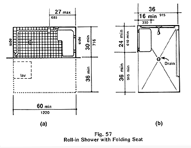
In public and common use bathing facilities with showers, does the shower stall size and clear floor space comply with either Figure 35(a) for a transfer type shower or Figure 35(b) for a roll-in shower? OR In guest rooms in transient lodging required to have roll-in showers, does the shower stall size and clear floor space comply with Figure 57(a) or 57(b)? | ||||
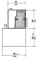
| 4.21.2 | Transfer Type Showers: | If the shower stall is a transfer type shown in Figure 35(a), is it exactly 36 by 36 inches? | |||
| Clear Floor Space: | In a transfer type shower, is there a clear floor space at least 36 by 48 inches outside the stall with 12 inches extending beyond the seat wall? (See Figure 35(a)) | ||||
| 4.21.3 | Seat: | In a transfer type shower, is there a seat mounted between 17 and 19 inches from the floor? | |||
| Does the seat extend the full depth of the stall? | |||||
| Is the seat L-shaped and as shown in Figure 36? | |||||
| Is the seat on the wall opposite the controls? | |||||
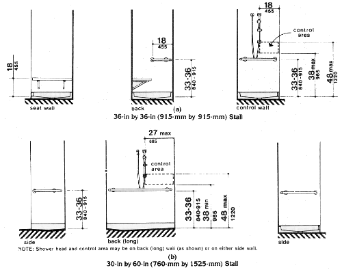
| 4.21.4 | Grab Bars: | In a transfer type shower, are grab bars provided between 33 and 36 inches above the floor along the control wall and half the back wall (but not behind the seat) as shown in Figure 37(a)? | |||
| 4.21.7 | Curbs: | If curbs are provided in a transfer type shower, are they no higher than 1/2 inch? | |||
| 4.21.5 | Faucets: | In a transfer type shower, are the faucets and other controls located within the area shown in Figure 37(a)? | |||
| 4.21.2 | Roll-in Showers - Public and Common Use: | In public or common use bathing facilities, if the shower stall is a roll-in type shown in Figure 35(b), is it at least 30 by 60 inches? | |||
| 4.21.2 | Is there at least a 36 by 60 inch clear floor space alongside the roll-in shower as shown in Figure 35(b)? | ||||
| 4.21.4 | Grab Bars: | In a roll-in shower, does a grab bar extend around three sides as shown in Figures 35(b) and 37(b)? | |||
| 4.21.7 | Curbs: | Is there no curb at the roll-in shower? | |||
| 4.21.5 | Faucets: | In a roll-in shower, are the faucets and other controls located on the back wall within the area shown in Figure 37(b) or on a side wall as shown in Figure 37(a)? | |||
| 9.1.2 4.21.2 |
Roll-in Showers - Transient Lodging: | In accessible guest rooms in transient lodging required to have roll-in showers, is there a shower complying with Figure 57(a)? OR Is there a shower complying with Figure 57(b)? | |||
| 4.21.3 | Seat: | In a roll-in shower required in accessible guest rooms in transient lodging, is there a folding seat affixed to the wall adjacent to the controls as shown in Figure 57(a) or 57(b)? | |||
| 4.21.4 | Grab Bars: | In a roll-in shower required in accessible guest rooms in transient lodging, are grab bars provided between 33 and 36 inches above the floor around two sides as shown in Figure 57(a) or 57(b)? | |||
| 4.21.7 | Curbs: | Is there no curb at the roll-in shower? | |||
| 4.21.5 | Faucets: | In a roll-in shower required in accessible guest rooms in transient lodging, are the faucets and other controls located within the area shown in Figure 57(a) or 57(b)? | |||
| 4.21.5 4.27.4 |
Faucets - All Accessible Showers: | In all accessible showers, can faucets and other controls be operated with one hand and without tight grasping, pinching, or twisting of the wrist? | |||
| Is the force required to operate the controls no greater than 5 lbf? | |||||
| 4.21.6 | Spray Unit - All Accessible Showers: | In all accessible showers, does the shower spray unit
have a hose at least 60 inches long? EXCEPTION: In unmonitored facilities where vandalism is a consideration, a fixed shower head mounted at 48 inches above the shower floor may be used in lieu of a hand-held shower head. |
|||
| Can the shower spray unit be used both as a hand-held and as a fixed shower head? | |||||
| 4.20.4 4.21.4 4.26.1 |
Grab Bars: | Do all grab bars for accessible bathtubs and showers comply with 4.26 (See below)? | |||
| 4.26.2 | Diameter: | Is the outside diameter of the grab bar between 1-1/4
inch and 1-1/2 inch? OR Does the shape provide an equivalent gripping surface? Note: Standard pipe sizes designated by the industry as 1-1/4 to 1-1/2 inches are acceptable for purposes of this section. |
|||
| Is the space between grab bars and walls exactly 1- 1/2 inches? | |||||
| 4.26.3 | Are the grab bars secured so that they do not rotate within the fittings? | ||||
| 4.26.2 | Clearance in Recess: | If a grab bar is located in a recess, is the recess a maximum of 3 inches deep extending at least 18 inches above the rail? | |||
| 4.26.3 | Structural Strength: | Do the grab bars meet the structural strength requirements for bending stress and shear stress in 4.26.3? | |||
| 4.26.3 | Do the fasteners meet the structural strength requirements for shear force and tensile force in 4.26.3? | ||||
| 4.26.4 | Hazards: | Are the grab bar edges free of sharp or abrasive elements and do edges have a minimum radius of 1/8 inch? | |||
| 4.20.3 4.21.3 4.26.3 |
Seats: | Do all seats for accessible bathtubs and showers meet the structural strength requirements for bending stress and shear stress in 4.26.3? | |||
| Do the fasteners meet the structural strength requirements for shear force and tensile force in 4.26.3? | |||||
| 4.21.8 | Shower Stall Enclosures: | If a shower stall enclosure is provided for an accessible shower, is it located so that it does not obstruct the controls or obstruct transfer from a wheelchair into the shower seat? |

Fig. 33(a) With Seat in Tub. If the approach is parallel to the bathtub, a 30 inch (760 mm) minimum width by 60 inch (1525 mm) minimum length clear space is required alongside the bathtub. If the approach is perpendicular to the bathtub, a 48 inch (1220 mm) minimum width by 60 inch (1525 mm) minimum length clear space is required.
Fig. 33(b) With Seat at Head of Tub. If the approach is parallel to the bathtub, a 30 inch (760 mm) minimum width by 75 inch (1905 mm) minimum length clear space is required alongside the bathtub. The seat width must be 15 inches (380 mm) and must extend the full width of the bathtub.
***

Fig. 34(a) With Seat in Tub. At the foot of the tub, the grab bar shall be 24 inches (610 mm) minimum in length measured from the outer edge of the tub. On the back wall, two grab bars are required. The grab bars mounted on the back (long) wall shall be a minimum 24 inches (610 mm) in length located 12 inches (305 mm) maximum from the foot of the tub and 24 inches (610 mm) maximum from the head of the tub. One grab bar shall be located 9 inches (230 mm) above the rim of the tub. The others shall be 33 to 36 inches ( 840 mm to 910 mm) above the bathroom floor. At the head of the tub, the grab bar shall be a minimum of 12 inches (305 mm) in length measured from the outer edge of the tub.
Fig. 34(b) With Seat at Head of Tub. At the foot of the tub, the grab bar shall be a minimum of 24 inches (610 mm) in length measured from the outer edge of the tub. On the back wall, two grab bars are required. The grab bars mounted on the back wall shall be a minimum of 48 inches (1220 mm) in length located a maximum of 12 inches (305 mm) from the foot of the tub and a maximum of 15 inches (380 mm) from the head of the tub. Heights of grab bars are as described above.
***

The clear floor space shall be a minimum of 48 inches (1220 mm)in length by a minimum of 36 inches (915 mm) in width and allow for a parallel approach. The clear floor space shall extend 1 foot beyond the shower wall on which the seat is mounted.
***

The clear floor space alongside the shower shall be a minimum of 60 inches (1220 mm) in length by a minimum of 36 inches (915 mm) in width.

Fig. 37(a) 36 inches by 36 inches (915 mm by 915 mm) Stall. The diagram illustrates an L-shaped grab bar that is located along the full depth of the control wall (opposite the seat) and halfway along the back wall. The grab bar shall be mounted between 33 to 36 inches (840-915 mm) above the shower floor. The bottom of the control area shall be a maximum of 38 inches (965 mm) high and the top of the control area shall be a maximum of 48 inches (1220 mm) high. The controls and spray unit shall be within 18 inches (455 mm) of the front of the shower.
Fig. 37(b) 30 inches by 60 inches (760 mm by 1525 mm) Stall. The diagram illustrates a U-shaped grab bar that wraps around the stall. The grab bar shall be between 33 to 36 inches (840-915 mm) high. The controls are placed in an area between 38 inches and 48 inches (965 mm and 1220 mm) above the floor. If the controls are located on the back (long) wall they shall be located 27 inches (685 mm) from the side wall. The shower head and control area may be located on either side wall.
***

Diagram (a): Where a fixed seat is provided in a 30 inch minimum by 60 inch (716 mm by 1220 mm) minimum shower stall, the controls and spray unit on the back (long) wall shall be located a maximum of 27 inches (685 mm) from the side wall where the seat is attached. (4.21.2, 9.1.2)
Diagram (b): An alternate 36 inch minimum by 60 inch (915 mm by 1220 mm) minimum shower stall is illustrated. The width of the stall opening stall shall be a minimum of 36 inches (915 mm) clear located on a long wall at the opposite end of the shower from the controls. The shower seat shall be 24 inches (610 mm) minimum in length by 16 inches (330 mm) minimum in width and may be rectangular in shape. The seat shall be located next to the opening to the shower and adjacent to the end wall containing the shower head and controls. (4.21.2, 9.1.2, A4.23.3)
Back to Accessibility Guidelines Checklist for Building and Facilities