
401.1 Scope. Accessible routes and accessible means of egress required by Chapter 2 shall comply with the applicable provisions of this chapter.
402.1 General. Accessible routes shall comply with 402.
402.2 Components. Accessible routes shall consist of one or more of the following components: walking surfaces with a slope not steeper than 1:20, doorways, ramps, elevators and platform (wheelchair) lifts. All components of an accessible route shall comply with the applicable portions of this chapter.
403.1 General. Walking surfaces that are a part of an accessible route shall comply with 403.
403.2 Floor or Ground Surface. Floor or ground surfaces shall comply with 302.
403.3 Slope. The running slope of walking surfaces shall be not steeper than 1:20. The cross slope of walking surfaces shall not be steeper than 1:48.
403.4 Changes in Level. Changes in level shall comply with 303.
403.5 Clear Width. The clear width of walking surfaces shall be 36 inches (915 mm) minimum.
EXCEPTION: The clear width shall be permitted to be reduced to 32 inches (815 mm) minimum for a length of 24 inches (610 mm) maximum, provided that reduced width segments are separated by segments that are 48 inches (1220 mm) minimum in length and 36 inches (915 mm) minimum in width.
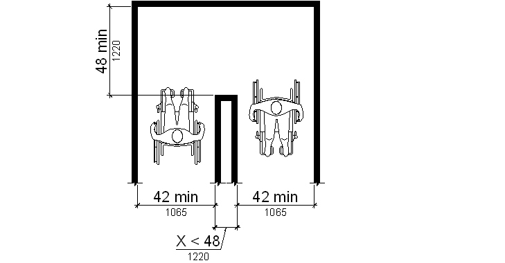
403.5.1 Clear Width at Turn. Where the accessible route makes a 180 degree turn around an object which is less than 48 inches (1220 mm) wide, clear width shall be 42 inches (1065 mm) minimum approaching the turn, 48 inches (1220 mm) minimum at the turn and 42 inches (1065 mm) leaving the turn.
| Figure 403.5.1 |
|---|
|
EXCEPTION: This requirement shall not apply where the clear width at the turn is 60 inches (1525 mm) minimum.
403.5.2 Passing Spaces. An accessible route with a clear width less than 60 inches (1525 mm) shall provide passing spaces at intervals of 200 feet (61 m) maximum. Passing spaces shall be either a 60 inch (1525 mm) minimum by 60 inch (1525 mm) minimum space, or an intersection of two walking surfaces which provide a T-shaped space complying with 304 provided that the stem and arms of the T-shaped space extend 48 inches (1220 mm) minimum beyond the intersection.
403.5.3 Protruding Objects. Protruding objects shall comply with 307. Protruding objects shall not reduce the required clear width.
Advisory 403.5.3
The
height of the clear or unobstructed space is considered
from the floor or ground to 80 inches (2030 mm) above the
floor or ground, unless specified otherwise.
404.1 General. Doors and doorways that are part of an accessible route shall comply with 404.
404.2 Manual Doors and Doorways. Manual doors and doorways and manual gates, including ticket gates, shall comply with 404.2.
EXCEPTION: Doors, doorways, and gates designed to be operated only by security personnel shall not be required to comply with 404.2.7, 404.2.8, and 404.2.9.
404.2.1 Revolving Doors and Turnstiles. Manual revolving doors and revolving turnstiles shall not be part of an accessible route.
404.2.2 Double-Leaf Doors. At least one of the active leaves of doorways with two independently operated leaves shall comply with 404.2.3 and 404.2.4.
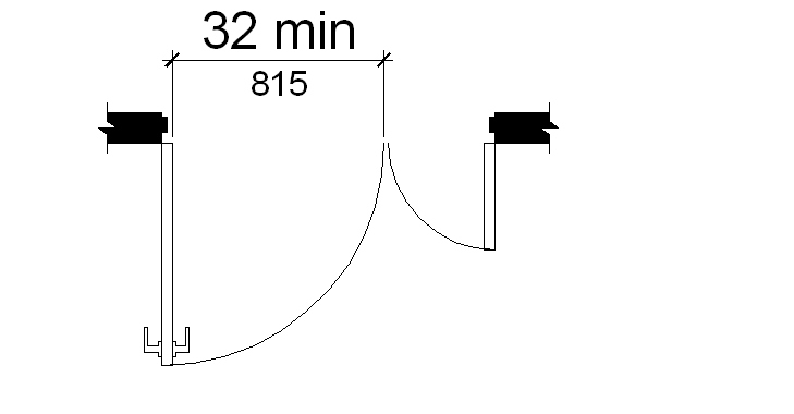
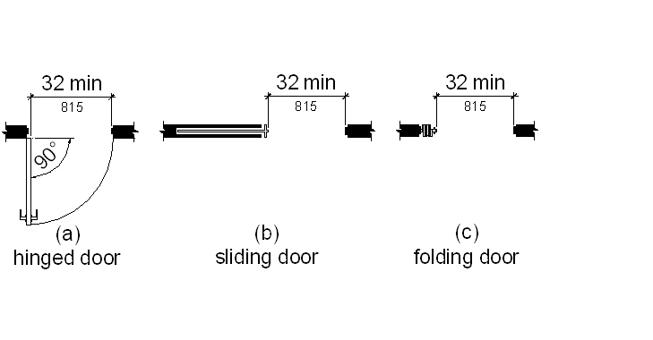
404.2.3 Clear Width. Doorways shall have a clear opening of 32 inches (815 mm) minimum. Clear openings of doorways with swinging doors shall be measured between the face of the door and the stop, with the door open 90 degrees. Openings more than 24 inches (610 mm) in depth shall provide a clear opening of 36 inches (915 mm) minimum. There shall be no projections into the required clear opening width lower than 34 inches (865 mm) above the floor or ground. Projections into the clear opening width between 34 inches (865 mm) and 80 inches (2030 mm) above the floor or ground shall not exceed 4 inches (100 mm).
EXCEPTION: In alterations, a projection of 5/8 inch (16 mm) maximum into the required clear width shall be permitted for the latch side stop.
404.2.4 Maneuvering Clearances.
404.2.4.1 Swinging Doors. Approaches to swinging doors shall have maneuvering clearances complying with Table 404.2.4.1.
| Table 404.2.4.1 Maneuvering Clearances at Manual Swinging Doors | |||
|---|---|---|---|
| Type of Use | Minimum Maneuvering Clearance1 | ||
| Approach Direction | Door Side | Perpendicular to Doorway | Parallel to Doorway (beyond latch side unless noted) |
| From front | Pull | 60 inches (1525 mm) | 18 inches (455 mm) |
| From front | Push | 48 inches (1220 mm) | 0 inches (0 mm)2 |
| From hinge side | Pull | 60 inches (1525 mm) | 36 inches (915 mm) |
| From hinge side | Pull | 54 inches (1370 mm) | 42 inches (1065 mm) |
| From hinge side | Push | 42 inches (1065 mm)3 | 22 inches (560 mm)4 |
| From latch side | Pull | 48 inches (1220 mm)5 | 24 inches (610 mm) |
| From latch side | Push | 42 inches (1065 mm)6 | 24 inches (610 mm) |
EXCEPTION: Doors to hospital patient sleeping rooms shall not be required to provide the clearance beyond the latch side of the door provided the door is 44 inches (1120 mm) wide minimum.
404.2.4.2 Doorways without Doors, Sliding Doors, and Folding Doors. Doorways less than 36 inches (915 mm) wide without doors, sliding doors, or folding doors shall have maneuvering clearances complying with Table 404.2.4.2.
| Table 404.2.4.2 Maneuvering Clearances at Doorways without Doors, Manual Sliding Doors, and Manual Folding Doors | ||
|---|---|---|
| Minimum Maneuvering Clearance7 | ||
| Approach Direction | Perpendicular to Doorway | Parallel to Doorway (beyond stop/latch side unless noted) |
| From Front | 48 inches (1220 mm) | 0 inches (0 mm) |
| From side8 | 42 inches (1065 mm) | 0 inches (0 mm) |
| From pocket/hinge side | 42 inches (1065 mm) | 22 inches (560 mm)9 |
| From stop/latch side | 42 inches (1065 mm) | 24 inches (610 mm) |
EXCEPTION: Doors to hospital patient sleeping rooms are exempt from the clearance beyond the stop/latch side of the door provided the door is 44 inches (1120 mm) wide minimum.
| Figure 404.2.4.2 |
|---|
| (a) front approach (b) pocket or hinge approach (c) stop or latch approach |
404.2.4.3 Recessed Doors. Recessed doors where the plane of the doorway is offset more than 8 inches (205 mm) from any obstruction within 18 inches (455 mm) measured laterally on the latch side of the door shall provide maneuvering clearances for front approach.
| Figure 404.2.4.3 |
|---|
| (a) pull side (b) push side (c) push side |
Advisory 404.2.4.3
A door
can be recessed due to wall thickness, or the placement
of casework, and other fixed elements. This provision
should be applied wherever doors are recessed.
404.2.4.4 Floor or Ground Surface. Floor or ground surface within required maneuvering clearances shall have a slope of 1:48 maximum and shall comply with 302. Changes in level, except at thresholds complying with 404.2.5, are not permitted.
404.2.5 Thresholds. Thresholds if provided at doorways shall be 1/2 inch (13 mm) maximum in height. Raised thresholds and changes in level at doorways shall comply with 302 and 303.
EXCEPTION: This requirement shall not apply to existing or altered thresholds 3/4 inch (19 mm) high maximum that have a beveled edge on each side.
404.2.6 Two Doors in Series. The distance between two hinged or pivoted doors in series shall be 48 inches (1220 mm) minimum plus the width of any door swinging into the space. Doors in series shall swing either in the same direction or away from the space between the doors.
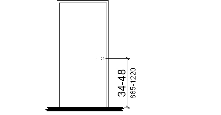
404.2.7 Door Hardware. Handles, pulls, latches, locks, and other operable parts on accessible doors shall comply with 309.4. Such hardware shall be 34 inches (865 mm) minimum and 48 inches (1220 mm) maximum above the floor or ground. When sliding doors are in the fully open position, operating hardware shall be exposed and usable from both sides.
Advisory 404.2.7
Door
hardware that can be operated with a closed fist or a
loose grip accommodates the greatest range of users.
Hardware that requires simultaneous hand and finger
movements require greater dexterity and coordination and
is not recommended.
EXCEPTION: Existing locks shall be permitted in any location at existing glazed doors without stiles, existing overhead rolling doors or grilles, and similar existing doors or grilles that are designed with locks that are activated only at the top or bottom rail.
404.2.8.1 Door Closers. Door closers shall be adjusted so that from an open position of 90 degrees, the time required to move the door to a position of 12 degrees from the latch is 5 seconds minimum.
404.2.8.2 Spring Hinges. Door spring hinges shall be adjusted so that from the open position of 70 degrees, the door shall move to the closed position in 1.5 seconds minimum.
404.2.9 Door Opening Force. Fire doors shall have a minimum opening force allowable by the appropriate administrative authority. The required force for pushing or pulling open a door other than fire doors shall be as follows:
1. Interior hinged doors: 5 lb (22.2 N) maximum.
2. Sliding or folding doors: 5 lb (22.2 N) maximum.
These forces do not apply to the force required to retract latch bolts or disengage other devices that hold the door in a closed position.
Advisory 404.2.9
The
maximum force pertains to the continuous application of
force necessary to fully open a door, not the initial
force needed to overcome the inertia of the door. It does
not apply to the force required to retract bolts or to
disengage other devices used to keep the door in a closed
position.
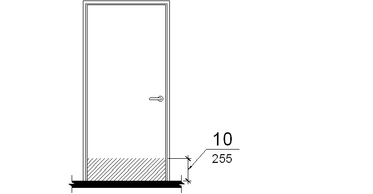
404.2.10 Door Surface. The bottom 10 inches (255 mm) of all swinging doors shall have a smooth surface on the push side and extending the full width of the door. Parts creating horizontal or vertical joints in such surface shall be within 1/16 inch (1.6 mm) of the same plane as the other. Cavities created by added kick plates shall be capped.
EXCEPTIONS: 1. This requirement shall not apply to sliding doors.
2. This requirement shall not apply to tempered glass doors without stiles and having a bottom rail or shoe with the top leading edge tapered at 60 degrees minimum from the horizontal.
3. This requirement shall not apply to doors that do not extend to within 10 inches (255 mm) of the floor or ground.
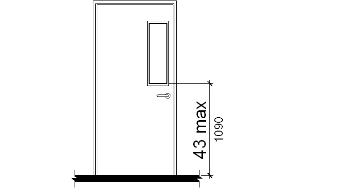
404.2.11 Vision Lites. Doors, and sidelites adjacent to doors, containing one or more glazing panels that permit viewing through the panels shall have the bottom of at least one glazed panel located 43 inches (1090 mm) maximum above the floor.
EXCEPTION: Vision lites with the lowest part more than 66 inches (1675 mm) from the floor or ground are not required to comply with this section.
404.3 Automatic Doors. Automatic doors and automatic gates shall comply with 404.3. Full-powered automatic doors shall comply with ANSI/BHMA A156.10. Low-energy and power-assisted doors shall comply with ANSI/BHMA A156.19. Automatic doors shall be permitted on an accessible route.
EXCEPTION: The requirements of 404.3.2 and 404.3.4 through 404.3.7 shall not apply to doors, doorways, and gates designed to be operated only by security personnel.
404.3.1 Clear Width. Doorways shall have a clear opening of 32 inches (815 mm) minimum in power-on and power- off mode. The minimum clear width for automatic door systems shall be based on the clear opening provided by all leafs in the open position.
404.3.2 Maneuvering Clearance. Clearances at power-assisted doors shall comply with 404.2.4.
404.3.3 Thresholds. Thresholds and changes in level at doorways shall comply with 404.2.5.
404.3.4 Two Doors in Series. Doors in series shall comply with 404.2.6.
404.3.5 Operable Parts. Manually operated control switches shall comply with 309 and shall be located outside the door swing.
404.3.6 Signs. Labels and warnings for automatic doors shall comply with 703.4.
404.3.7 Break Out Opening. When an automatic door is operated in emergency mode, the clear break out opening for a swinging or sliding automatic door shall be 32 inches (815 mm) minimum.
405.1 General. Ramps along accessible routes shall comply with 405.
405.2 Slope. Ramp runs shall have a running slope not steeper than 1:12.
| Table 405.2 Maximum Ramp Slope and Rise for Existing Sites, Buildings and Facilities | |
|---|---|
| Slope10 | Maximum Rise |
| Steeper than 1:10 but not steeper than 1:8 | 3 inches (75 mm) |
| Steeper than 1:12 but not steeper than 1:10 | 6 inches (150 mm) |
EXCEPTIONS: 1. Ramps in or on existing buildings or facilities shall be permitted to have slopes steeper than 1:12 complying with Table 405.2 where such slopes are necessitated by space limitations.
2. In alterations to qualified historic buildings and facilities where exceptions for alterations are permitted by Chapter 2, the slope of a ramp run of 24 inches (610 mm) maximum shall not be steeper than 1:6.
405.3 Cross Slope. Cross slope of ramp runs shall not be steeper than 1:48.
Advisory 405.3
Cross
slope is the slope of the surface perpendicular to the
direction of travel. It is measured the same way as slope
is measured: the rise over the run.
405.4 Floor or Ground Surfaces. Floor or ground surfaces of ramp runs shall comply with 302. Changes in level other than the running slope and cross slope are not permitted on ramp runs.
405.5 Clear Width. The clear width of a ramp run and the clear width between handrails, if provided, shall be 36 inches (915 mm) minimum.
405.6 Rise. The rise for any ramp run shall be 30 inches (760 mm) maximum.
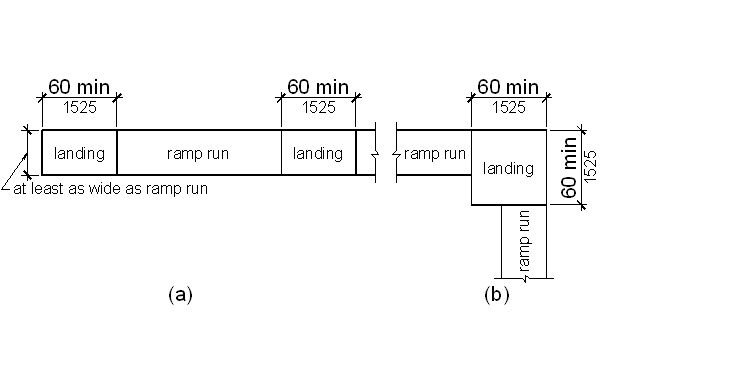
405.7 Landings. Ramps shall have landings at bottom and top of each ramp run. Landings shall comply with 405.7.
Advisory 405.7
Ramps
that do not have level landings at changes in direction
can create a compound slope that will not meet the
requirements of this document. A level landing at doors
and doorways is needed for maneuvering at the door while
simultaneously operating hardware.
405.7.1 Slope. Landings shall comply with 302. Changes in level are not permitted.
EXCEPTION: Slopes not steeper than 1:48 shall be permitted.
405.7.2 Width. The landing shall be at least as wide as the widest ramp run leading to the landing.
405.7.3 Length. The landing length shall be 60 inches (1525 mm) minimum.
405.7.4 Change in Direction. Ramps that change direction between runs at landings shall have a 60 inch (1525 mm) minimum by 60 inch (1525 mm) minimum landing.
405.7.5 Doorways. Where doorways are located adjacent to a ramp landing, maneuvering clearances required by 404.2.4 and 404.3.2 shall be permitted to overlap the required landing area.
405.8 Handrails. Ramp runs with a rise greater than 6 inches (150 mm) shall have handrails complying with 505.
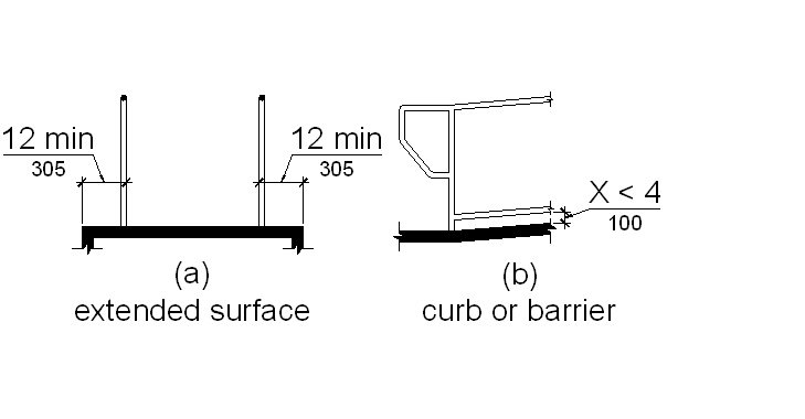
405.9 Edge Protection. Edge protection complying with 405.9.1 or 405.9.2 shall be provided on each side of ramp runs and at each side of ramp landings.
EXCEPTIONS: 1. Edge protection is not required on ramps that are not required to have handrails and have sides complying with 406.3.
2. Edge protection is not required on the sides of ramp landings serving an adjoining ramp run or stairway.
3. Edge protection is not required on the sides of ramp landings having a vertical drop-off of 1/2 inch (13 mm) maximum within 10 inches (255 mm) horizontally of the minimum landing area.
405.9.1 Extended Floor or Ground Surface. The floor or ground surface of the ramp run or landing shall extend 12 inches (305 mm) minimum beyond the inside face of a handrail complying with 505.
Advisory 405.9.1
The
extended surface is provided to prevent wheelchair
casters and crutch tips from slipping off the ramp
surface.
405.9.2 Curb or Barrier. A curb or barrier shall be provided that prevents the passage of a 4 inch (100 mm) diameter sphere, where any portion of the sphere is within 4 inches (100 mm) of the floor or ground surface.
405.10 Wet Conditions. Landings subject to wet conditions shall be designed to prevent the accumulation of water.
406.1 General. Curb ramps on accessible routes shall comply with 406 and with 405.2, 405.4, 405.5, and 405.10.
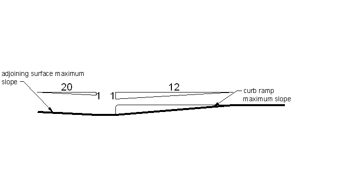
406.2 Counter Slope. Counter slopes of adjoining gutters and road surfaces immediately adjacent to the curb ramp shall not be steeper than 1:20. The adjacent surfaces at transitions at curb ramps to walks, gutters, and streets shall be at the same level.
406.3 Sides of Curb Ramps. Curb ramps located where pedestrians must walk across the ramp shall have flared sides. Slope of the flares shall not be steeper than 1:10. Where the width of the walking surface at the top of the ramp and parallel to the run of the ramp is less than 48 inches (1220 mm) wide, the flared sides shall have a slope not steeper than 1:12. Curb ramps with returned curbs shall be permitted where pedestrians would not normally walk across the ramp.
406.4 Handrails. Handrails are not required on curb ramps.
406.5 Location at Marked Crossings. Curb ramps at marked crossings shall be wholly contained within the markings, excluding any flared sides.
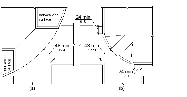
406.6 Diagonal Curb Ramps. Diagonal or corner type curb ramps with returned curbs or other well-defined edges shall have the edges parallel to the direction of pedestrian flow. The bottom of diagonal curb ramps shall have 48 inches (1220 mm) minimum of clear space. Diagonal curb ramps provided at marked crossings shall provide the 48 inches (1220 mm) minimum clear space within the markings. Diagonal curb ramps with flared sides shall have a segment of straight curb 24 inches (610 mm) long minimum located on each side of the curb ramp and within the marked crossing.
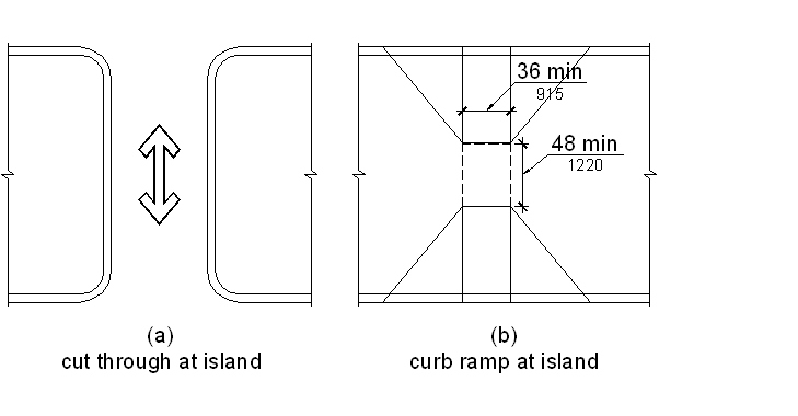
406.7 Islands. Raised islands in crossings shall be cut through level with the street or have curb ramps at both sides. Each curb ramp shall have a level area 48 inches (1220 mm) long minimum by 36 inches (915 mm) wide minimum at the top of the curb ramp in the part of the island intersected by the crossings. Each 48 inch (1220 mm) by 36 inch (915 mm) area shall be oriented so that the 48 inch (1220 mm) length is in the direction of the running slope of the curb ramp it serves. The 48 inch (1220 mm) by 36 inch (915 mm) areas and the accessible route shall be permitted to overlap.
406.8 Location. Curb ramps shall be located so that they do not project into vehicular traffic lanes, parking spaces, or parking access aisles.
407.1 General. New elevators required to be accessible shall comply with 407.2. New destination-oriented elevators required to be accessible shall comply with 407.3. New limited use/limited application elevators required to be accessible shall comply with 407.4. Altered elements of existing elevators shall comply with 407.5.
407.2 New Elevators. New accessible elevators shall comply with 407.2 and with ASME/ANSI A17.1. They shall be passenger elevators as classified by ASME/ANSI A17.1.
407.2.1 Automatic Operation. Elevator operation shall be automatic. Each car shall be equipped with a self-leveling feature that will automatically bring and maintain the car at floor landings within a tolerance of 1/2 inch (13 mm) under rated loading to zero loading conditions.
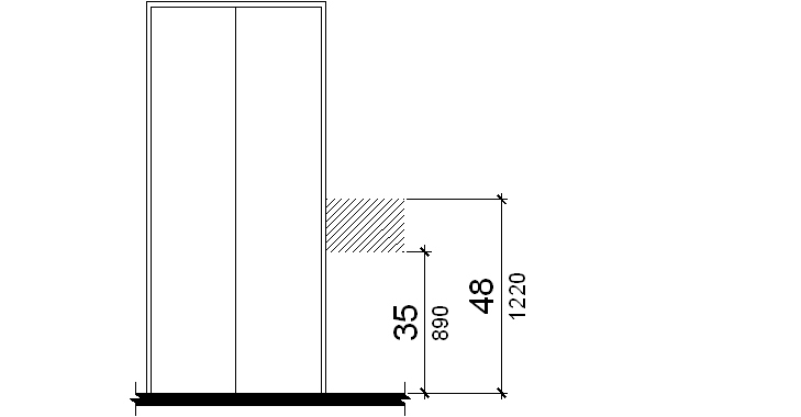
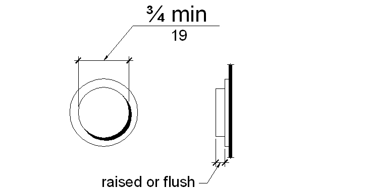
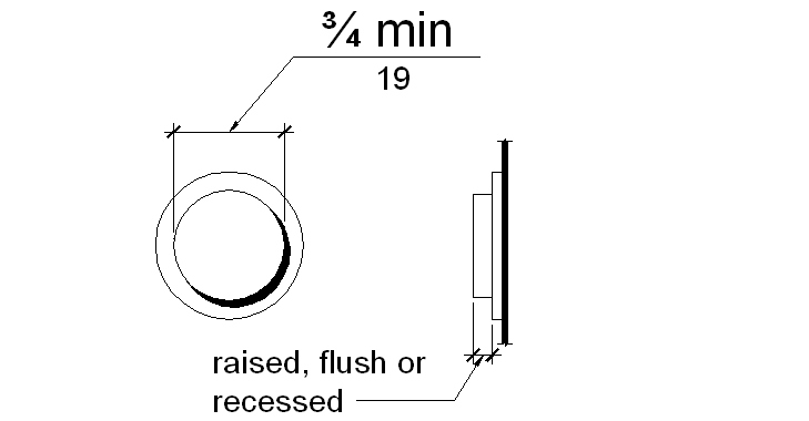
407.2.2 Call Buttons. Call buttons in elevator lobbies and halls shall be located vertically between 35 inches (890 mm) and 48 inches (1220 mm) above the floor, measured to the centerline of the button. A clear floor space complying with 305 shall be provided. Such call buttons shall have visible signals to indicate when each call is registered and when each call is answered. Call buttons shall be 3/4 inch (19 mm) minimum in the smallest dimension. The button that designates the up direction shall be located above the button that designates the down direction. Buttons shall be raised or flush. Objects located beneath hall call buttons shall protrude 4 inches (100 mm) maximum into the clear floor space.
407.2.3 Hall Signals. A visible and audible signal shall be provided at each hoistway entrance to indicate which car is answering a call and the direction of travel. Alternatively, in-car signals shall be located in cars, visible from the floor area adjacent to the hall call buttons, and shall comply with the requirements of this section.
407.2.3.1 Audible Signals. Audible signals shall sound once for the up direction and twice for the down direction, or shall have verbal annunciators that state the word "up" or "down." Audible signals or verbal annunciators shall have a frequency of 1500 Hz maximum. The audible signal or verbal annunciator shall be 20 dBA minimum and 80 dBA maximum, measured at the hall call button.
407.2.3.2 Visible Signals. Visible signals shall comply with 407.2.3.2.
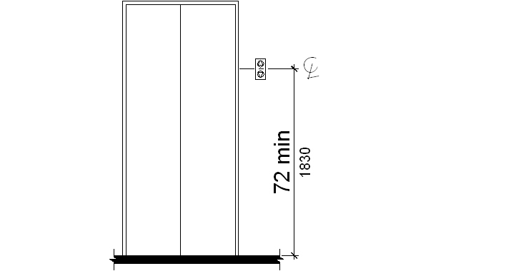
407.2.3.2.1 Height. Hall signal fixtures shall be centered at 72 inches (1830 mm) minimum above the floor or ground.
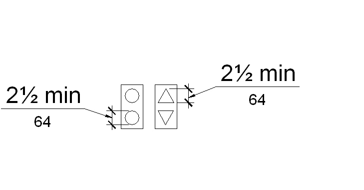
407.2.3.2.2 Size. The visible signal elements shall be 2-1/2 inches (64 mm) minimum measured along the vertical centerline of the element.
407.2.3.2.3 Visibility. Signals shall be visible from the floor area adjacent to the hall call button.
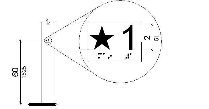
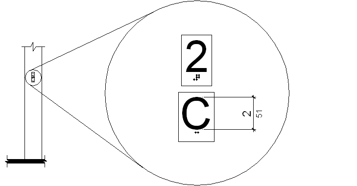
407.2.4 Tactile Signs on Hoistway Entrances. Tactile character and Braille floor designations shall be provided on both jambs of elevator hoistway entrances and shall be 60 inches (1525 mm) above the floor, measured from the baseline of the characters. A tactile star shall also be provided on both jambs at the main entry level. Such characters shall be 2 inches (51 mm) high and shall comply with 703.2.
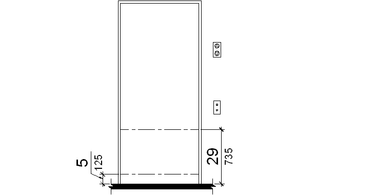
407.2.5 Door Operation. Elevator doors shall be the horizontal type. Elevator hoistway and car doors shall open and close automatically. Elevator doors shall be provided with a reopening device that shall stop and reopen a car door and hoistway door automatically if the door becomes obstructed by an object or person. The device shall be activated by sensing an obstruction passing through the opening at 5 inches (125 mm) and 29 inches (735 mm) above the floor. The device shall not require physical contact to be activated, although contact may occur before the door reverses. Door reopening devices shall remain effective for 20 seconds minimum.
407.2.6 Door and Signal Timing for Hall Calls. The minimum acceptable time from notification that a car is answering a call or designation of which car is assigned to a lobby destination floor entry until the doors of that car start to close shall be calculated from the following equation:
T = D/(455 mm/s) = 5 seconds minimum
where T equals the total time in seconds and D equals the distance (in feet or millimeters) from the point in the lobby or corridor 60 inches (1525 mm) directly in front of the farthest call button controlling that car to the centerline of its hoistway door. For cars with in-car lanterns, T begins when the signal is visible from the point 60 inches (1525 mm) directly in front of the farthest hall call button and the audible signal is sounded.
407.2.7 Door Delay for Car Calls. Elevator doors shall remain fully open in response to a car call for 3 seconds minimum.
407.2.8 Inside Dimensions of Elevator Cars. Clear width of elevator doors and inside dimensions of elevator cars shall comply with Table 407.2.8.
| Table 407.2.8 Elevator Door and Car Sizes | ||||
|---|---|---|---|---|
| Minimum Dimensions | ||||
| Door Location | Door Clear Width | Inside Car, Side to Side | Inside Car, Back Wall to Front Return | Inside Car, Back Wall to Inside Face of Door |
| Centered | 42 inches (1065 mm) | 80 inches (2030 mm) | 51 inches (1295 mm) | 54 inches (1370 mm) |
| Side (off-centered) | 36 inches (915 mm)11 | 68 inches (1725 mm) | 51 inches (1295 mm) | 54 inches (1370 mm) |
| Any | 36 inches (915 mm)1 | 54 inches (1370 mm) | 80 inches (2030 mm) | 80 inches (2030 mm) |
| Any | 36 inches (915 mm)1 | 60 inches (1525 mm)12 | 60 inches (1525 mm)2 | 60 inches (1525 mm)2 |
| Figure 407.2.8 |
|---|
| (a) centered door (b) off-centered door (c) (d) |
407.2.9 Floor Surfaces. Floor surfaces in elevator cars shall comply with 302. The clearance between the car platform sill and the edge of any hoistway landing shall be 1-1/4 inch (32 mm) maximum.
407.2.10 Illumination Levels. The level of illumination at the car controls, platform, car threshold and car landing sill shall be 5 footcandles (54 lux) minimum.
407.2.11 Car Controls. Elevator controls shall comply with 407.2.11.
407.2.11.1 Buttons. Buttons shall be 3/4 inch (19 mm) minimum in their smallest dimension. Buttons shall be raised or flush. Buttons shall be arranged with numbers in ascending order. When two or more columns of buttons are provided they shall read from left to right. Keypads, where provided, shall be in a standard telephone keypad arrangement.
407.2.11.2 Designations and Indicators for Control Buttons. Control buttons shall be identified by tactile characters complying with 703.2. Characters and Braille shall be placed immediately to the left of the button to which the designations apply. The control button for the main entry floor and control buttons, other than remaining buttons with floor designations, shall be identified with tactile symbols as shown in Table 407.2.11.2. Buttons with floor designations shall be provided with visible indicators to show that a call has been registered. The visible indication shall extinguish when the car arrives at the designated floor. Where provided, telephone-style keypad buttons shall be identified by tactile characters complying with 703.2 except that Braille is not required. Characters shall be centered on the corresponding keypad button.
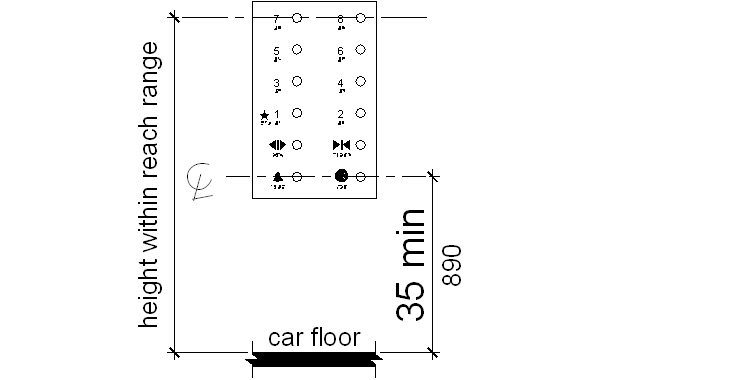
407.2.11.3 Height. Buttons with floor designations shall be located within one of the reach ranges specified in 308. Emergency controls, including the emergency alarm, shall be grouped at the bottom of the panel. Emergency control buttons shall have their centerlines 35 inches (890 mm) minimum above the floor.
407.2.11.4 Location. Controls shall be located to accommodate a forward reach or side reach as specified in 308.
407.2.12 Car Position Indicators. In elevator cars, audible and visible car location indicators shall be provided.
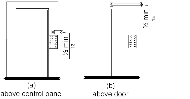
407.2.12.1 Visible Indicators. Indicators shall be located above the car control panel or above the door. Numerals shall be 1/2 inch (13 mm) high minimum. As the car passes a floor and when a car stops at a floor served by the elevator, the corresponding character shall illuminate.
407.2.12.2 Audible Indicators. The audible signal shall be 20 dBA minimum and 80 dBA maximum, measured at the annunciator, and shall have a frequency of 1500 Hz maximum. The signal shall be an automatic verbal announcement which announces the floor at which the car has stopped.
EXCEPTION: For elevators that have a rated speed of 200 feet per minute (1 m/s) or less, an audible signal with a frequency of 1500 Hz maximum which sounds as the car passes or stops at a floor served by the elevator shall be permitted.
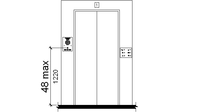
407.2.13 Emergency Communications. Emergency two-way communication systems between the elevator car and a point outside the hoistway shall comply with ASME/ANSI A17.1. The highest operable part of a two-way communication system shall be 48 inches (1220 mm) maximum above the floor. The device shall be identified by tactile characters complying with 703.2 located adjacent to the device. If the system uses a handset, the cord from the panel to the handset shall be 29 inches (735 mm) long minimum. The car emergency signaling device shall not be limited to voice communication. If instructions for use are provided, essential information shall be presented in both tactile and visual form.
407.3 New Destination-Oriented Elevators. New accessible destination-oriented elevators shall comply with 407.2.1, 407.2.4 through 407.2.10, and 407.2.13. Such elevators shall also comply with 407.3 and ASME/ANSI A17.1. They shall be passenger elevators as classified by ASME/ANSI A17.1.
407.3.1 Call Buttons. Call buttons shall be located vertically between 35 inches (890 mm) and 48 inches (1220 mm) above the floor, measured to the centerline of the button. A clear floor space complying with 305 shall be provided. Call buttons shall be 3/4 inch (19 mm) minimum in the smallest dimension. Buttons shall be raised or flush. Objects located beneath hall call buttons shall protrude 4 inches (100 mm) maximum into the clear floor space. A keypad or other means for the entry of destination information shall be provided. Keypads, where provided, shall be in a standard telephone keypad arrangement. Visible and audible signals which indicate which elevator car to enter shall be provided.
407.3.2 Hall Signals. A visible and audible signal shall be provided to indicate a car destination corresponding with 407.3.1. The audible tone and verbal announcement shall be the same as those given at the call button or call button keypad. Each elevator in a bank shall have audible and visible means for differentiation.
407.3.2.1 Visible Signals. Visible signals shall comply with 407.3.2.1.
407.3.2.1.1 Height. Hall signal fixtures shall be centered at 72 inches (1830 mm) minimum above the floor or ground.
407.3.2.1.2 Size. The visible signal elements shall be 2-1/2 inches (64 mm) minimum measured along the vertical centerline of the element.
407.3.2.1.3 Visibility. Signals shall be visible from the floor area adjacent to the hoistway entrance.
407.3.3 Car Controls. Emergency controls, including the emergency alarm, shall have their centerlines 35 inches (890 mm) minimum and 48 inches (1220 mm) maximum above the floor. Buttons shall be 3/4 inch (19 mm) minimum in their smallest dimension. Buttons shall be raised or flush. Controls shall be located to accommodate a forward reach or side reach as specified in 308.
407.3.4 Car Position Indicators. In elevator cars, audible and visible car location indicators shall be provided.
407.3.4.1 Visible Indicators. Indicators shall be located above the car control panel or above the door. Numerals shall be 1/2 inch (13 mm) high minimum. A display shall be provided in the car with visible indicators to show car destinations. The visible indicators shall extinguish when the call has been answered.
407.3.4.2 Audible Indicators. An automatic verbal announcement which announces the floor at which the car has stopped shall be provided. The announcement shall be 20 dBA minimum and 80 dBA maximum, measured at the annunciator.
407.3.5 Elevator Car Identification. In addition to the tactile signs required by 407.2.4, a tactile elevator car identification shall be placed immediately below the hoistway entrance floor designation. The characters shall be 2 inches (51 mm) high and shall comply with 703.2.
407.4 New Limited-Use/Limited-Application Elevators. New accessible limited-use/limited application elevators shall comply with 407.4 and shall comply with ASME/ANSI A17.1, Part XXV.
407.4.1 Automatic Operations. Elevator operation shall be automatic. Each car shall automatically stop at a floor landing within a tolerance of 1/2 inch (13 mm) under rated loading to zero loading conditions.
407.4.2 Call Buttons. Call buttons in elevator lobbies and halls shall be located vertically between 35 inches (890 mm) and 48 inches (1220 mm) above the floor, measured to the centerline of the button. Such call buttons shall have visible signals to indicate when each call is registered and when each call is answered. Call buttons shall be 3/4 inch (19 mm) minimum in the smallest dimension, and shall be raised or flush. The button that designates the up direction shall be located above the button that designates the down direction. Objects located beneath hall call buttons shall protrude into the floor area adjacent to the hoistway entrance 4 inches (100 mm) maximum.
407.4.3 Hall Signals. A visible and audible signal complying with 407.2.3 shall be provided in the car or at each hoistway entrance to indicate the direction of travel.
407.4.4 Tactile Signs on Hoistway Entrances. Tactile character and Braille floor designations shall be provided on both jambs of elevator hoistway entrances and shall be 60 inches (1525 mm) above the floor measured from the baseline of the characters. Such characters shall be 2 inches (51 mm) high minimum and shall comply with 703.2.
407.4.5 Door Operation. Elevator hoistway doors shall be either swinging or horizontally sliding type. Elevator hoistway and car doors shall open and close automatically. Horizontally sliding type hoistway and car doors shall comply with 407.2.5. Swinging hoistway doors shall conform to 404. Swinging doors shall be low-energy power-operated and shall comply with ANSI/BHMA A156.1.9. Power-operated swing doors shall remain open for 20 seconds minimum when activated.
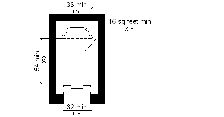
407.4.6 Inside Dimensions of Elevator Cars. Elevator cars shall provide a clear width of 42 inches (1065 mm) minimum and a clear depth of 54 inches (1370 mm) minimum. For installations in existing buildings or facilities, elevator cars shall provide a clear width of 36 inches (915 mm) minimum, a clear depth of 54 inches (1370 mm) minimum, and a net clear platform area of 15 square feet (1.4 m2) minimum. Car doors shall be positioned at the narrow end of the car and shall provide a clear width of 32 inches (815 mm) minimum.
| Figure 407.4.6 |
|---|
| (a) limited use/limited application (new construction) (b) limited use/limited application (existing facility) |
407.4.7 Floor Surfaces. Floor surfaces in elevator cars shall comply with 302. The horizontal distance between the car platform sill and the edge of any hoistway landing shall be 1-1/4 inches (32 mm) maximum.
407.4.8 Illumination Levels. The level of illumination at the car controls, platform, and car threshold and landing sill shall be 5 footcandles (53.8 lux) minimum.
407.4.9 Car Controls. Elevator controls shall comply with 407.2.11. Controls shall be centered on a side wall and shall comply with 309.
407.4.10 Emergency Communications. Car emergency signaling devices complying with 407.2.13 shall be provided.
407.5 Existing Elevators. Altered elements of existing destination-oriented elevators shall comply with 407.3. Altered elements of existing limited-use/limited-application elevators shall comply with 407.4. Altered elements of all other existing elevators shall comply with 407.2.1, 407.2.4, 407.2.6, 407.2.7, 407.2.9, 407.2.10 and 407.2.13 and with 407.5 or shall comply with 407.2. They shall be passenger elevators as classified by ASME/ANSI A17.1.
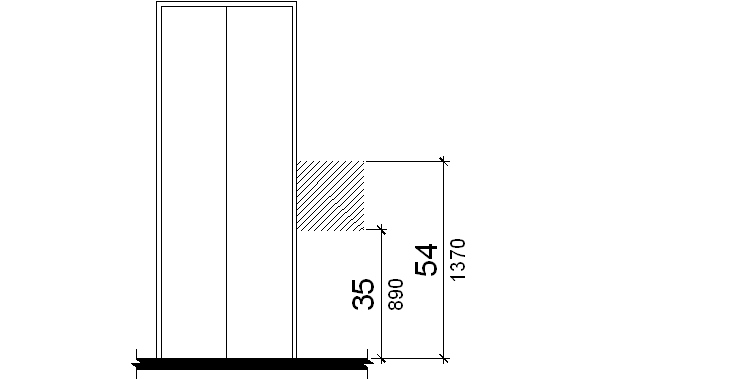
407.5.1 Call Buttons. Call buttons in elevator lobbies and halls shall be located vertically between 35 inches (890 mm) and 54 inches (1370 mm) above the floor, measured to the centerline of the button. A clear floor or ground space complying with 305 shall be provided. The button that designates the up direction shall be located above the button that designates the down direction. Keypad controls, if provided, shall comply with 407.2.11.
407.5.2 Hall Signals. A visible and audible signal at each hoistway entrance to indicate which car is answering a call or in-car signals complying with 407.2.3 shall be provided. Audible signals shall sound once for the up direction and twice for the down direction, or shall have verbal annunciators that state the word "up" or "down". If new hall signals are installed, they shall comply with 407.2.3.
407.5.3 Door Operation. Power-operated horizontally sliding car and hoistway doors opened and closed by automatic means shall comply with 407.2.5. Existing manually operated hoistway swing doors shall comply with 404.2.3 and 404.2.9. A power-operated car door that opens and maintains a 32 inches (815 mm) minimum clear width shall be provided. Closing of the car door shall not be initiated until the hoistway door is closed. Car gates are prohibited.
407.5.4 Inside Dimensions of Elevator Cars. The inside dimensions of elevator cars shall comply with 407.2.8.
EXCEPTION: This requirement shall not apply to existing elevator car configurations that provide a clear floor area of 16 square feet (1.5 m2) minimum, and provide 54 inches (1370 mm) minimum inside clear depth and 36 inches (915 mm) minimum clear width.
407.5.5 Car Controls. Elevator controls shall comply with 407.5.5.
407.5.5.1 Buttons. Control buttons shall be 3/4 inch (19 mm) minimum in their smallest dimension. Control buttons shall be raised, flush or recessed. Where the car operating panel is changed, control buttons shall comply with 407.2.11.1.
407.5.5.2 Designations and Indicators for Control Buttons. Control buttons shall comply with 407.2.11.2.
EXCEPTION: Where space on an existing car operating panel precludes tactile markings to the left of the controls, markings shall be placed as near to the control as possible.
407.5.5.3 Height. Floor buttons shall be located 54 inches (1370 mm) maximum above the floor for parallel approach and 48 inches (1220 mm) maximum for front approach. Where the panel is changed, it shall comply with 407.2.11.3.
407.5.5.4 Operating Panels. Where a new car operating panel complying with 407.2.11 is provided, existing car operating panels shall not be required to comply with 407.2.11.
407.5.6 Car Position Indicators. Where a new car position indicator is provided, the indicator shall comply with 407.2.12.
407.5.7 Identification. Accessible elevators shall be clearly identified with the International Symbol of Accessibility complying with 703.7, unless all elevators in the building or facility are accessible.
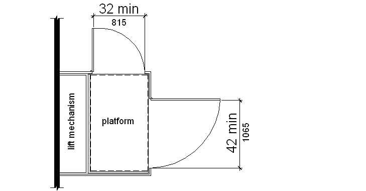
408.1 General. Wheelchair (platform) lifts shall comply with ASME/ANSI A17.1 and with 302, 305 and 309. Wheelchair (platform) lifts shall not be attendant-operated and shall provide unassisted entry and exit from the lift.
Advisory 408.1
Inclined
stairway chairlifts and inclined and vertical platform
lifts are available for short-distance vertical
transportation. Because an accessible route requires an
80 inch (2030 mm) vertical clearance, care should be
taken in selecting lifts as they may not be equally
suitable for use by wheelchair users and standees. If a
lift does not provide 80 inch (2030 mm) vertical
clearance, it cannot be considered part of an accessible
route in new construction.
408.2 Doors and Gates. Lifts shall have low-energy power-operated doors or gates complying with 404.3. Doors and gates shall remain open for 20 seconds minimum. End doors shall be 32 inches (815 mm) minimum clear width. Side doors shall be 42 inches (1065 mm) minimum clear width.
EXCEPTION: Lifts having doors or gates on opposite sides shall be permitted to have self-closing manual doors or gates.
409.1 General. Each required accessible means of egress shall be continuous to a public way and shall consist of one or more of the following components: accessible routes complying with 402, exit stairways complying with 409.2, elevators complying with 409.3, horizontal exits or smoke barriers. Wheelchair (platform) lifts shall not serve as part of an accessible means of egress.
409.2 Exit Stairways. An exit stairway to be considered part of an accessible means of egress shall conform to 504 and shall have a clear width of 48 inches (1220 mm) minimum between handrails and shall either incorporate an area of refuge within an enlarged floor-level landing or shall be accessed from either an area of refuge complying with 410 or a horizontal exit.
EXCEPTIONS: 1. This requirement shall not apply to exit stairways serving a single guest room.
2. This requirement shall not apply to exit stairways in buildings or facilities protected throughout by a supervised automatic sprinkler system.
Advisory 409.2 Exception 2
Supervised
automatic sprinkler systems have built-in signals for
monitoring features of the system which indicate
conditions that will impair the satisfactory operation of
the sprinkler system.
3. The clear width of 48 inches (1220 mm) between handrails is not required for exit stairways accessed from a horizontal exit.
4. This requirement shall not apply to exit stairways serving open parking garages.
409.3 Elevators. An elevator to be considered part of an accessible means of egress shall comply with the requirements of Rule 211 of ASME/ANSI A17.1 and standby power shall be provided. The elevator shall be accessed from either an area of refuge complying with 410 or a horizontal exit.
EXCEPTIONS: 1. Elevators are not required to be accessed from an area of refuge or horizontal exit in open parking garages.
2. Elevators are not required to be accessed from an area of refuge or horizontal exit in buildings and facilities protected throughout by a supervised automatic sprinkler system.
410.1 General. Where areas of refuge are required, they shall comply with 410.
EXCEPTION: Areas of refuge are not required in detention and correctional facilities.
410.2 Location. Each area of refuge shall be accessed from the space it serves by an accessible route which serves as an accessible means of egress. The maximum travel distance to an area of refuge shall not exceed the travel distance permitted for the occupancy by the administrative authority. Every area of refuge shall have direct access to an exit stairway complying with 409.2 or an elevator complying with 409.3.
410.3 Size. Each area of refuge shall be sized to accommodate one wheelchair space complying with 305.3 for each 200 occupants or fraction thereof, based on the occupant load of the area of refuge and all areas served by the area of refuge. Such wheelchair spaces shall not overlap the required means of egress width. Access to any required wheelchair space shall not be through more than one adjoining wheelchair space.
410.4 Construction. Each area of refuge shall be separated from the remainder of the story by a smoke barrier having a one-hour minimum fire-resistance rating. Smoke barriers shall extend to the floor or roof deck above. Doors in the smoke barrier shall have a 20 minute minimum fire-resistance rating. Doors shall be self-closing or automatic closing by smoke detection. HVAC openings in smoke barriers, where permitted, shall be ducted and provided with a smoke-actuated damper designed to resist the passage of smoke.
410.5 Smoke Resistance. Every area of refuge shall be designed to prevent the intrusion of smoke.
EXCEPTIONS: 1. This requirement shall not apply where the areas of refuge and all areas served by the area of refuge are protected by a supervised automatic sprinkler system.
2. This requirement shall not apply to areas of refuge located within an exit stair enclosure.
410.5.1 Elevator Lobby. Where an elevator lobby is used as an area of refuge, the elevator hoistway and lobby shall be pressurized to comply with the requirements for smokeproof enclosures, except where elevators are in an area of refuge formed by a horizontal exit or smoke barrier.
410.6 Communication System. Every area of refuge shall be provided with an accessible two-way communication system between the area of refuge and a central control point. The communication system shall have both audible and visible signals.
Advisory 410.6
The
two-way communication system must be equipped with both
audible signals and visual signals and cannot operate
solely through voice communication. Audible signals can
include voice output or recorded messages. A button that
lights to indicate that help is on the way when the call
is answered is an acceptable visual signal.
410.7 Instructions. In each area of refuge provided with a two-way communication system, instructions on the use of the area under emergency conditions shall be posted adjacent to the communications system. The instructions shall include:
1. Directions to other means of egress.
2. Advice that persons able to use the exit stairs do so as soon as possible unless they are assisting others.
3. Information on planned availability of assistance in the use of stairs or supervised operation of elevators and how to summon such assistance.
4. Directions for use of emergency communications system.
410.8 Identification. Each area of refuge shall be identified by a tactile sign stating "Area of Refuge" complying with 703.2 and including the International Symbol of Accessibility complying with 703.7. A sign shall be located at each door providing access to the area of refuge. The sign shall be illuminated as required for exit signs where exit sign illumination is required.
1. Maneuvering clearances shall include the full width of the doorway.
2. Add 12 inches (305 mm) if closer and latch are provided.
3. Add 6 inches (150 mm) if closer and latch are provided.
5. Add 6 inches (150 mm) if closer and latch are provided.
6. Add 6 inches (150 mm) if closer and latch are provided.
7. Maneuvering clearance shall include the full width of the doorway.
10. A slope steeper than 1:8 is prohibited.
11. A tolerance of minus 5/8 inch (16 mm) is permitted.
12. Other car configurations that provide a wheelchair turning space complying with 304 with the door closed are permited.


