|
BACKGROUND
The cross section of a road includes some or all of the following elements:
- Traveled way (the portion of the roadway provided for the movement
of vehicles, exclusive of shoulders)
- Roadway (the portion of a highway, including shoulders, provided
for vehicular use)
- Median area (the physical or painted separation provided on divided
highways between two adjacent roadways)
- Bicycle and pedestrian facilities
- Utility and landscape areas
- Drainage channels and side slopes
- Clear zone width (i.e., the distance from the edge of the traveled
way to either a fixed obstacle or nontraversable slope)
Considered as a single unit, all these crosssection elements define the highway
rightofway. The rightofway can be described generally as the publicly owned
parcel of land that encompasses all the various crosssection elements (see Figures
6.1 and 6.2).
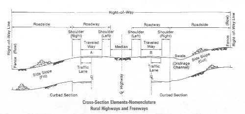 |
Figure 6.1
Twolane rural highway crosssection design features and terms.
|
Some decisions about cross section are made during project development, such
as the capacity and number of lanes for the facility. Other decisions, such
as functional classification, are made earlier in the process. Within these
parameters, the Green Book guidelines recommend a range of values for the dimensions
to use for crosssectional elements. Deciding which of the elements to include
and selecting the appropriate dimensions within these ranges is the role of
the designer.
|
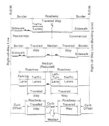
Figure 6.2
Urban highway crosssection design features and terms.
|
 |
In selecting the appropriate crosssection elements and dimensions, designers
need to consider a number of factors, including the following:
- Volume and composition (percent trucks, buses, and recreational vehicles)
of the vehicular traffic expected to use the facility
- The likelihood that bicyclists and pedestrians will use the route
- Climatic conditions (e.g., the need to provide storage space for plowed
snow)
- The presence of natural or humanmade obstructions adjacent to the roadway
(e.g., rock cliffs, large trees, wetlands, buildings, power lines)
- Type and intensity of development along the section of the highway facility
that is being designed
- Safety of the users
The most appropriate design for a highway improvement is the one that balances
the mobility needs of the people using the facility (motorists, pedestrians,
or bicyclists) with the physical constraints of the corridor within which the
facility is located.
|
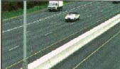
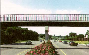
The likelihood of pedestrian and bicycle traffic is one
factor to consider when designing the cross section of a facility.
|
 |
CROSSSECTION ELEMENTS
Travel Lanes
The number of lanes needed for a facility is usually determined during the
concept stage of project development. It is usually the number of lanes necessary
to accommodate the expected traffic volumes at a level of service determined
to be appropriate for the facility (see Chapter 4 for a discussion of level
of service). The number of lanes can only be added in integer units, i.e., a
twolane highway can be widened to three or four lanes. Each additional lane
represents an increase in the trafficcarrying capability of the facility.
Knowing future projected travel demands, the designer, using the analysis procedures
in the Highway Capacity Manual, can provide input into the decisionmaking process
during project development to determine the appropriate number of travel lanes
for the level of service desired. Community input also plays a part in this
decision. A community may decide through public involvement that a lower level
of service is acceptable for the situation than the level of service normally
provided for new construction projects.
In urban and suburban areas, signalized intersections are usually the predominant
factor controlling the capacity of the highway or street. There may be more
latitude in determining the number of lanes for these types of facilities. For
example, a twolane facility approaching an intersection can be expanded to four
lanes (one left turn lane, two through lanes, one rightturn lane) at the intersection
itself and then returned to two lanes beyond the intersection. The need to distribute
traffic safely will determine the need for any expansion of the approach roadway.
The added lanes at the intersection can be in a variety of configurations to
serve the travel desires of the traffic.
Lane Width
The width of travel lanes is limited by the physical dimensions of automobiles
and trucks to a range between 2.7 and 3.6 m (9 and 12 ft). Generally, as the
design speed of a highway increases, so must the lane width to allow for the
lateral movement of vehicles within the lane. However, constricted rightofway
and other design restrictions can have an impact on this decision. Chapter IV
of the Green Book recognizes the need for flexibility in these cases:
Although lane widths of 3.6 m are desirable on both rural and urban
facilities, there are circumstances that necessitate the use of lanes less
than 3.6 m wide. In urban areas where rightofway and existing development
become stringent controls, the use of 3.3 m lanes is acceptable. Lanes 3.0
m wide are acceptable on lowspeed facilities. Lanes 2.7 m wide are appropriate
on lowvolume roads in rural and residential areas.
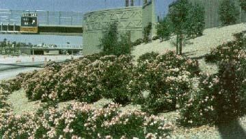
|
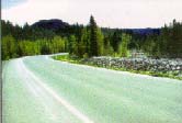
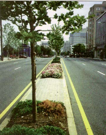
A landscaped median.
(I35E, St. Paul, MN)
|
 |
Medians
An important consideration in the design of any multilane highway is whether
to provide a median and, if one is provided, what the dimensions should be.
The primary functions of highway medians are to:
- Separate opposing traffic flows
- Provide a recovery area for outofcontrol vehicles
- Allow space for speed changes and leftturning and Uturning vehicles
- Minimize headlight glare
- Provide width for future lanes (particularly in suburban areas)
- Provide a space for landscape planting that is in keeping with safety needs
and improves the aesthetics of the facility
- Provide a space for barriers.
Depending on agency practice and specific location requirements, medians may
be depressed, raised, or flush with the surface of the traveled way. Medians
should have a dimension that is in balance with the other elements of the total
highway cross section. The general range of median widths is from 1.2 m (4 ft),
usually in urban areas, to 24 m (80 ft) or more, in rural areas. An offset of
at least a 500 mm (1.5 ft) should be provided between any vertical element located
within the median, such as a curb or barrier, and the edge of the adjacent traveled
lane.
The design and width of medians again require tradeoffs for designers. In
locations where the total available rightofway is restricted, a wide median
may not be desirable if it requires narrowing the areas adjacent to the outside
edge of the traveled way. A reasonable border width is required to serve as
a buffer between private development along the road and the edge of the traveled
way, and space may be needed for sidewalks, highway signs, utilities, parking,
drainage channels and structures, proper slopes and clear zones, and any retained
native plant material. On the other hand, wider medians provide more space for
plant material, offer a refuge for pedestrians at intersections, and help soften
the look of the roadway. Including and designing medians requires public input
to find the design that meets the needs of the community.
|
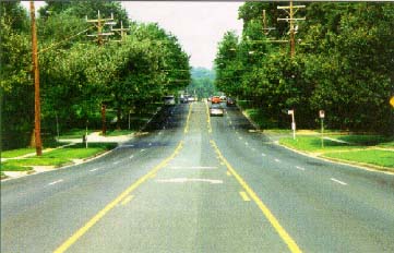
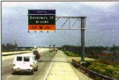
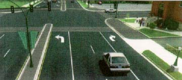
Twoway leftturn lanes improve safety and efficiency
for vehicular traffic but do not afford a safe refuge for pedestrians.
|
 |
The use of twoway leftturn lanes on urban streets in densely developed suburban
commercial areas has increased as an alternative to raised medians with leftturn
or Uturn bays. Although not as aesthetically pleasing as raised, planted medians,
continuous leftturn lanes can improve capacity. Twoway leftturn lanes generally
are not recommended in residential areas because they do not afford a safe refuge
for pedestrians. Also, the number of driveways can create unsafe vehicle maneuvers.
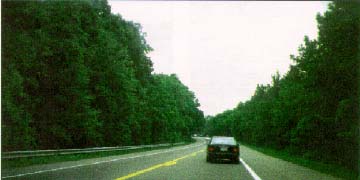 |
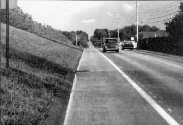
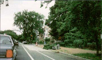
Shoulders increase safety and highway capacity and provide a place for
pedestrians and bicyclists when no sidewalks are provided.
(Rt. 197, MD)
|
Shoulders
Although the physical dimensions of automobiles and trucks limit the basic
width of travel lanes, the treatment of that portion of the highway to the right
of the actual traveled way, that is, the "roadway edge," provides
the designer with a greater degree of flexibility. This is true in both urban
and rural areas, although different design elements are more appropriate in
each location.
Shoulder widths typically vary from as little as 0.6 m (2 ft) on minor rural
roads, where there is no surfacing, to about 3.6 m (12 ft) on major highways,
where the entire shoulder may be stabilized or paved.
The treatment of shoulders is important from a number of perspectives, including
safety, the capacity of the highway section, impact on the surrounding environment,
and both the initial capital outlay and ongoing maintenance and operating costs.
The shoulder design should balance these factors. For example, a designer must
consider the impact of the shoulder width and other roadside elements on the
surrounding environment and, at the same time, how these dimensions will affect
capacity. Even with a maximum lane width of 3.6 m (12 ft), the absence of a
shoulder or the presence of an obstruction at the edge of the travel lane can
result in a reduction in capacity of as much as 30 percent, compared to an area
where shoulder or clear zone exists that is a minimum 1.8 m (6 ft) wide. On
the other hand, significant environmental, scenic, or historic resources may
be adversely affected by a widened shoulder.
Another consideration is the accommodation of pedestrians and nonmotorized
vehicles. In many parts of the country, highway shoulders provide a separate
traveled way for pedestrians, bicyclists, and others (when no sidewalks are
provided).
(a) |
(b) |
Various shoulder treatments:
(a) Gravel
(b) Paved
(c) Concrete
(d) Grass with sidewalk
|
(c) |
(d) |
In addition to the dimensions of shoulders, designers have choices to make
about the materials used. Shoulders may be surfaced for either their full or
partial widths. Some of the commonly used materials include gravel, shell, crushed
rock, mineral or chemical additives, bituminous surface treatments, and various
forms of asphaltic or concrete pavements.
In a number of States, particularly in the southern part of the country where
snow removal is not an issue, grass or turf surfaces have been provided on top
of compacted earth embankments. The advantages of grass shoulders are that they
provide both a natural storm water detention system and are aesthetically pleasing.
The disadvantages can be that they are often less safe than paved shoulders
and force pedestrians and bicyclists to share the road with motorists, if no
offstreet facility is provided.
Shoulders represent an important element in roadway drainage systems by carrying
surface runoff away from the travel lanes into either open or closed drainage
systems. A variety of design treatments have been used to accommodate roadway
drainage across shoulder areas. In rural and suburban areas, the most common
technique allows surface runoff to cross over the shoulder and go directly into
drainage ditches running parallel to the roadway edge.
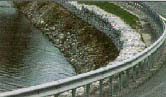
In rural areas where significant physical and/or environmental constraints
exist, more "urban" style solutions have been used. For example, along
an older section of Maryland State Route 51, passing through the Green Ridge
State Forest in Allegany County, steep, narrow cuts along the existing alinement
severely limited the total roadway width. Asphalt curbing and a closed drainage
system were constructed in conjunction with a recent pavement rehabilitation
project. This allowed for a modest widening of the travelway and elimination
of an area of steep and narrow ditches, without the need to engage in major
earthwork.
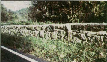
|
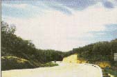
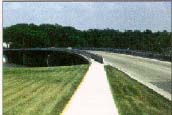
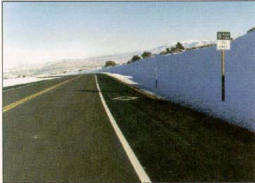
Use of paved shoulder, asphalt curbing, and closed drainage
system along a rural minor arterial.
|
 |
Clear Zones
An important consideration in defining the appropriate cross section for a
particular highway facility is the width of the clear zone. As defined in Chapter
IV of the AASHTO Green Book, the clear zone is "...the unobstructed,
relatively flat area provided beyond the edge of the traveled way for the recovery
of errant vehicles."
The width of the clear zone is influenced by several factors, the most important
of which are traffic volume, design speed of the highway, and slope of the embankments.
The AASHTO Roadside Design Guide' is a primary reference for determining clear
zone widths for freeways, rural arterials, and highspeed rural collectors based
on these factors. For lowspeed rural collectors and rural local roads, the AASHTO
Green Book suggests providing a minimum clear zone width of 3.0 m (IO ft). For
urban arterials, collectors, and local streets with curbs, the space available
for clear zones is typically restricted. 1 Roadside Design Guide,
AASHTO, Washington, DC, January 1996.
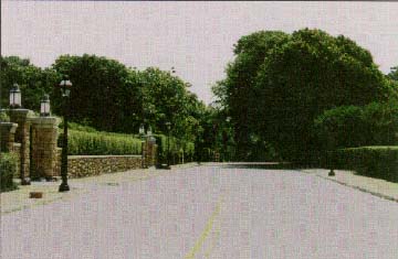
Curbs
Used primarily in urban and suburban environments, curbs can serve some or
all of the following functions:
- Drainage control
- Roadway edge delineation
- Rightofway reduction
- Aesthetics
- Delineation of pedestrian walkways
- Reduction of maintenance operations
- Assistance in roadside development.
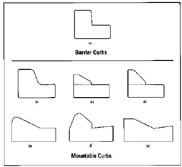
There are basically two types of curbs: barrier and mountable. Flexibility
in the use of either type is a handy tool for a highway designer when defining
the cross section of an improvement project. Barriertype curbs are not, however,
recommended for projects with design speeds above 65 km/h (40 mph).
Curbs can be constructed from a variety of materials, including concrete, asphalt,
and cut stone. Figure 6.3 illustrates a variety of commonly used barrier and
mountable curbs.
|
Figure 6.3 Examples of barrier and mountable
curbs.
|
 |
Sidewalks and Pedestrian Paths
The safe and efficient accommodation of pedestrians along the traveled way
is equally important as the provisions for vehicles. Too often, pedestrians
are a secondary consideration in the design of roadways, particularly in suburban
areas. Although sidewalks are an integral part of city streets, they are much
more rare in rural areas and provided only sporadically in suburban areas, despite
data that suggest that providing sidewalks along highways in rural and suburban
areas results in a reduction in pedestrian accidents.
 |
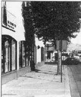 |
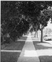
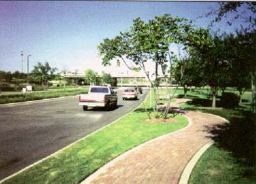
Sidewalks can be located next to a planted strip or flush with the
roadside edge.
|
When considering the placement of sidewalks, designers have several options.
The sidewalk can either be placed flush with the roadside edge (if a curb is
provided) or next to a buffer area, such as a planted strip (usually of grass
or plant material), located between the sidewalk and roadside. The pros and
cons of each option should be weighed and considered by the designer, using
input from the community. For example, a planted strip has these advantages:
- Pedestrians are kept at a greater distance from moving vehicles and thus
are safer (in urban areas with onstreet parking, parked cars help to act as
a shield for pedestrians from moving traffic, so a buffer space may not be
necessary to address that concern).
- Planted strips tends to add to the aesthetics of the facility and help reduce
the apparent width of hard surface space.
- Planted strips provide a space for snow storage.
Buffers, or planted strips, may have the disadvantage of requiring additional
rightofway that may negatively affect restricted rightofway corridors.
Another important consideration, and one in which the designer is given some
flexibility, is in the width of the sidewalk and planted strip. Typically, sidewalks
in residential or lowdensity commercial areas vary in width from 1.2 to 2.4
m (4 to 8 ft). The Americans with Disabilities Act Accessibility Guidelines
of August 1992 set the minimum passing width on a sidewalk at 1.525 m (5 ft)
at least every 61 m (200 ft). If a planted strip is provided between the sidewalk
and the curb, it should be at least 0.6 m (2 ft) wide to allow for maintenance
activities. This planted strip also provides space for street lights, fire hydrants,
street hardware, and landscaping.
|
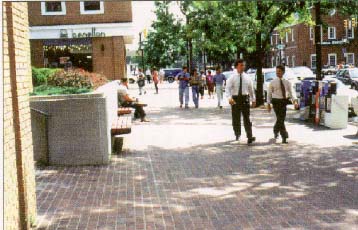
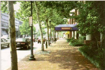
The wider the sidewalk, the more room there is for street
furniture, trees, utilities, and pedestrians. (Alexandria, VA)
|
 |
Sidewalks can also provide space for street furniture and necessary traffic
poles and signals; however, additional width should be added to sidewalks to
accommodate these fixtures. The wider the sidewalk, the greater the number of
pedestrians that can be accommodated and the less difficult it is for them to
maneuver around these fixed objects. When considering the placement of objects
inside sidewalks, it is important not to overlook the need to maintain as unobstructed
a pathway as possible. For instance, locating utility poles to the sides and
not in the center, of sidewalks is important. This detail facilitates the movements
of people with disabilities as well.
Adding sidewalks to a facility where none previously existed can be beneficial
to a community. When the Lincoln Beach Parkway section of the Pacific Coast
Highway (U.S. Route 101) was reconstructed in the early 1990's, sidewalks were
added along both sides of the facility. Not only did this result in a more aesthetically
pleasing alternative to the shoulder section for the two travel lanes that previously
existed, but the sidewalks made it safer for residents to walk between their
homes and local commercial facilities. Residents can now interact with each
other much more easily, which has fostered a higher level of community spirit.
|
Sidewalks can be built with a variety of shapes and
materials.
(San Antonio, TX)
|
 |
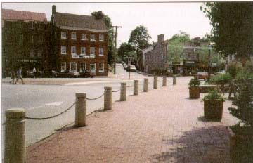 |
Pedestrian barriers can provide safety by separating pedestrian and
vehicular traffic.
(Annapolis, MD)
|
|
Street trees and light fixtures are carefully lined
to one side of the sidewalk to provide the widest possible space for pedestrians.
|
 |
Accommodating Bicycles
Bicycles are recognized by many as a viable mode of transportation in the United
States, both for commuting and recreation. Transportation designers should consider
the needs of these users in the design of facilities. Basically, there are five
types of bicycle facilities:
- Shared lane - a "standardwidth" travel lane that both bicycles
and motor vehicles share
- Wide outside lane - an outside travel lane with a width of
at least 4.2 m (14 ft) to accommodate both bicyclists and motorized vehicles
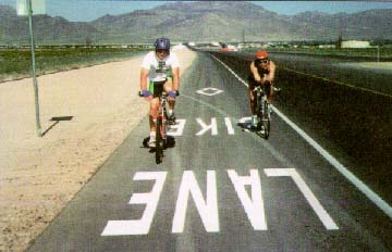
- Bicycle lane - a portion of the roadway designated by striping, signing,
and/or pavement markings for preferential or exclusive use by bicycles and/or
other nonmotorized vehicles
- Shoulder - a paved portion of the roadway to the right of the traveled
way designed to serve bicyclists, pedestrians and others
- Multiuse path - a facility that is physically separated from the
roadway and intended for use by bicyclists, pedestrians, and others
|
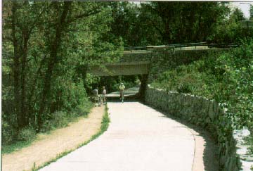
A multiuse path.
|
 |
There are three primary factors to consider when designing facilities to accommodate
bicycles and other nonmotorized vehicles:
- What type of bicyclist is the route most likely to serve, i.e., advanced
bicyclists, basic bicyclists, or children?
Advanced bicyclists are the experienced riders who make up the majority
of the current users of collector and arterial streets, wish to operate
at maximum speed with minimum delays, and require sufficient space on the
roadway shoulder to be treated as vehicles. Designated bicycle lanes along
a roadway give riders an even greater degree of comfort along arterial and
collector streets. Basic bicyclists and children generally prefer the most
comfortable, although sometimes circuitous, access to destinations, using
lowspeed, lowtrafficvolume streets or a separate, multiuse path.
- What type of roadway project is involved, i.e., new construction, major
reconstruction, or minor rehabilitation?
Recommended design treatments are most easily implemented when new construction
or major reconstruction is planned. Although retrofit and/or enhancement
projects may be relatively limited in scope, opportunities to make at least
minor improvements to better accommodate the needs of pedestrians and bicycles
should be investigated. Marginal roadway improvements undertaken as part
of 3R projects, such as widening the pavement area 0.3 to 0.6 m (1 to 2
ft) will enhance the roadway for bicycle use.
- What are the current and future traffic operations and design characteristics
of the route that will affect the choice of bicycle design treatments?
|
The shoulders on SR 313 were specifically designed to
accommodate bicycle traffic.
(Moab, UT)
|
 |
Six factors are recognized by transportation planners and engineers as having
the greatest effect on bicycle use:
- Traffic volume-higher traffic volumes represent greater potential
risk for bicycles.
- Average motor vehicle operating speed-operating speed is more important
than the posted speed limit; motor vehicle operating speed can negatively
affect the bicyclist's comfort unless mitigated by special design treatments.
- Traffic mix-the presence of trucks, buses, and other large vehicles
can increase risk and have a negative impact on the comfort of bicyclists.
- Onstreet parking-additional width is needed for bicycle lanes on
roads that have onstreet parking.
- Sight distance-this must be sufficient to allow a motor vehicle operator
to either change lane position or slow to the bicyclist's speed when overtaking
the bicycle, primarily on rural highways.
- Number of intersections-the number and frequency of intersections
should be considered when assessing the use of bike lanes. Intersections pose
special challenges to bicycle and motor vehicle operators and require special
treatments.
|
East Capitol Street accommodates two travel lanes, onstreet
parking, and a designated bike lane in each direction.
(Washington, DC)
|
 |
 |
The highway landscape is an important part of its overall appearance.
(Papago Freeway, Phoenix, AZ)
|
Landscape Design and Selection of Plant Material
Landscape design is an important element in the design of all highway facilities
and should be considered early in the process, so that it is in keeping with
the character or theme of the highway and its environment. The AASHTO Green
Book mentions three objectives of landscape design:
- To provide vegetation that will be an aid to aesthetics and safety
- To provide vegetation that will aid in lowering construction and maintenance
costs
- To provide vegetation that creates interest, usefulness, and beauty for
the pleasure and satisfaction of the traveling public
Landscape designs for urban highways and streets plays an additional role in
mitigating the many nuisances associated with urban traffic and can help a roadway
achieve a better "fit" with its surroundings.
|
Landscape treatment is most successfully integrated
into a project when considered early in the design.
(OR)
|
 |
Trees
An important aspect of roadside landscape design is the treatment of trees.
Singlevehicle collisions with trees account for nearly 25 percent of all fixedobject
fatal accidents annually and result in the deaths of approximately 3,000 people
each year. This problem is most apparent on roads that have existing trees,
where designers do not have direct control over placement. For landscape projects,
where the type and location of trees and other vegetation can be carefully chosen,
the potential risks can be minimized.
Integrating trees into the design of a facility has many advantages. Trees
provide a visual "edge" to the roadway that helps guide motorists.
Trees also add to the aesthetic quality of a highway. In urban and suburban
areas, trees soften the edges of arterial and collector streets. If sight distance
is a concern, taller trees with lower branches that are trimmed or lowgrowing
(shorter than I m [3 ft]) herbaceous and woody plants can be another option
along both the roadway edge and in raised medians.
 |
Trees add to the visual appeal of this urban street and can be placed
in both medians and along roadway edges.
|
|
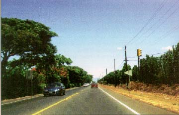
Trees make a difference. Compare the left side of this
roadway with the right side, where the trees have been removed.
(Rt 30, Maui, HI)
|
 |
It is important to select the appropriate species of tree for the highway environment.
In particular, trees need to be chosen that can survive poor air quality, infertile
and compacted soils, and extreme temperature fluctuations. Remember that maintenance,
particularly during the first year after installation, is essential to the longterm
health and viability of trees and other plants. Utilize the skills and knowledge
of the city or town urban forester or arborist, the local agricultural extension
service, or a landscape architect to identify the plant material that will be
best suited for the location.
In addition to selecting a type of tree for its hardiness, the size and placement
of trees is another important consideration. Generally, a tree with a trunk
diameter greater than 100 mm (4 in) measured 100 mm (4 in) above the ground
line is considered a "fixed object" along the roadway. Because most
trees grow larger than this, their placement along the roadway needs to be carefully
considered. Factors that affect this decision include the design speed, traffic
volume, roadway cross section, and placement of guardrail. Trees should not
be placed in the clear zone for any new construction or major reconstruction,
nor should they be considered safe because they are placed just outside the
clear zone. The safe placement of trees to prevent errant drivers from hitting
them should be made in conjunction with a highway designer who is knowledgeable
about safety. However, the decision to create a clear zone that requires the
removal of existing trees is an issue that should be presented to the public
and addressed by the multidisciplinary team early on.
Trees are an important aspect of community identity and carry a great deal
of emotional ties with the residents. If communities consider existing trees
a valuable resource, alternatives to complete eradication should be pursued.
These include installation of traffic barriers, lowering of the design speed,
or even complete redesign of the facility to incorporate the trees. It is not
unusual for a community to value one specific tree and desire to preserve it.
In general, transportation designers must balance safety with other community
values when considering facility design and tree preservation.
Utilities
One element of crosssection design that is often overlooked is the accommodation
of public utilities. Overhead utilities typically include electric, telephone,
and cable television. For new construction in urban areas, electric, telephone,
and other telecommunication lines are now often placed underground.
Motor vehicle collisions with utility poles result in approximately 10 percent
of all fixedobject fatal crashes in the United States annually. Utility poles
also have a negative affect on the aesthetics of a roadway. It is important,
therefore, whether designing in rural or urban locations, to consider accommodating
utilities early in the design process.
The most desirable design solution, in terms of safety for overhead utilities,
is to locate the utility poles where they are least likely to be struck by a
vehicle. (The same is true for sign and luminaire supports.) The 1996 AASHTO
Roadside Design Guidenotes the following options for the location and
design of utilities:
- Bury power and telephone lines underground
- Increase lateral pole offset
- Increase pole spacing
- Combine pole usage with multiple utilities
- Use a breakaway pole design
- Use traffic barriers to shield poles
Burying power and telephone lines, although the safest and most aesthetically
pleasing option, is also the most expensive. For example, during the reconstruction
of 1.66 km (1.03 miles) of Carson Street in the city of Torrance, CA, all the
existing overhead utilities were placed underground at a cost of about $2.3
million, or approximately 37 percent of the total project cost. Because of these
tradeoffs, the design and location of utilities requires public input and should
be considered early in the design of each project.
Traffic Barriers
The options available to designers for traffic barriers include deciding whether
or not to include them in the design and, if they are included, deciding which
type to choose. The purpose of the barrier, as stated in the AASHTO Green Book,
is to "minimize the severity of potential accidents involving vehicles
leaving the traveled way where the consequences of errant vehicles striking
a barrier are less than leaving the roadway." In addition to preventing
collisions with fixed objects along the roadside, traffic barriers are themselves
obstacles and have some degree of accident potential. The use of traffic barriers
should consider these tradeoffs.
A wide variety of traffic barriers is available for installation along highways
and streets, including both longitudinal barriers and crash cushions. Longitudinal
barriers (such as guardrails and median barriers) are designed primarily to
redirect errant vehicles and keep them from going beyond the edge of the roadway.
Crash cushions primarily serve to decelerate errant vehicles to a complete stop
(such as impact attenuators at freeway exit gore areas) .
The design of the traffic barrier is an important detail that contributes to
the overall look or theme of roadway design; therefore, in addition to safety,
the selection of an appropriate barrier design should include aesthetic considerations.
In addition, all traffic barriers should meet crashtesting guidelines for the
type of roadway being designed. Crashtesting guidelines have different levels,
depending on the facility and the type of vehicles that will use the facility.
For example, on parkways with restricted truck traffic, many aesthetic barriers
have been designed and crash tested. The criteria used for these types of barriers
are less stringent than the criteria for facilities with truck traffic. Because
aesthetic considerations are usually a factor on parkways, many of these barriers
are designed to add to the visual quality of the road. Even for roads that are
not parkways, however, there are still many barrier designs that meet the criteria
for facilities with truck traffic. Given these options, designers must balance
their decisions based on safety, cost, and aesthetics.
|
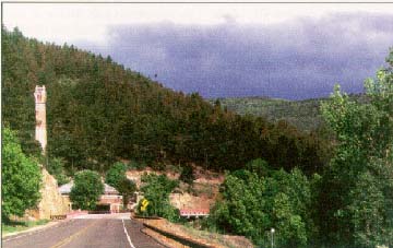
Weathering steel is a lowcost option for designers
who are trying to "blend" a barrier into the surrounding environment.
(NM 65, Montezuma, NM)
|
 |
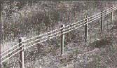
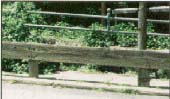
A sample of available traffic barrier designs includes:
- A threestrand cable barrier system allowing deflections on impact of up
to 4.6 m (15 ft)
- Various steel beam barriers allowing deflections on impact of up to 1.2
m (4 ft)
- Steelbacked timber barriers that allow deflections on impact of up to 2.4
m (8 ft)
- New Jersey shaped concrete barriers
- Stone masonry walls consisting of a reinforced concrete core faced with
stone masonry.
(e)
An indepth discussion of the factors associated with the decision
to install traffic barriers and guidance on the selection of a particular barrier
design is presented in the AASHTO Roadside Design Guide.
A concern among some States when selecting a barrier design is cost. Aesthetic
barriers might have a higher upfront cost than standard steel barriers and may
be more expensive to maintain. One solution to this concern is to be consistent
in the type of aesthetic barrier used throughout a State. For instance, a State
might want to limit the type of barriers used to only two, an inexpensive barrier
for highways where aesthetics are not a major concern and an aesthetic type
for highways where visual quality is important. In this way, States can cut
back on the cost to maintain multiple barrier designs.
Weathering steel guardrails are an example of an inexpensive barrier that may
be considered acceptable in certain surroundings. For many States, weathering
steel has been a good solution, because its rustic color helps the guardrail
blend into the environment. Weathering steel has, however, had durability problems
in a few areas.
|
These HO V lanes are restricted to buses, vanpools,
and carpools carrying three or more occupants. (I84, CT)
|
 |
Accommodating Transit
Highways operate as truly multimodal transportation facilities, particularly
in large urban areas. Accommodating public transit and other highoccupancy vehicles
(HOVs) is an important consideration. On one end of the scale, this may involve
including sidewalks to allow local residents to walk to and from bus stops.
As higher levels of vehicle traffic and transit usage are expected, bus turnouts
may need to be considered. At the higher end of the scale, such as on major
urban freeways, dedicated bus lanes and/or HOV lanes may need to be incorporated
into the design. The management of the local public transit operator should
be consulted during the planning stage, if possible, so that these facilities
can be incorporated into the design from the beginning.
ISSUES
Some of the challenging aspects of highway design have to do with crosssection
elements. Decisions that designers need to make may include the number of lanes
proposed for the improvement, the width of travel lanes and shoulder areas,
the type of drainage proposed, or the desirability of including sidewalks or
bicycle/pedestrian paths as part of the project.
Restricted RightofWay
Many roads currently exist that were not built to today's standards. These
roads may be located in restricted rightofway corridors that have scenic or
historic resources adjacent to the roadway. It is necessary to try to avoid
impacting these resources when considering highway improvements.
Solution
One option, as has been discussed previously, is to reconsider the functional
classification and design speed of a particular section of highway, because
these decisions go a long way toward defining the basic design parameters that
can be used in connection with an improvement of the facility. Lowering the
design speed or changing the functional classification results in a lowering
of the minimum width dimensions for the crosssectional elements.
Another option is to maintain the road as is or as a 3R project. Design criteria
established by States are generally lower for 3R projects than for reconstruction
projects. A third option is to seek design exceptions. Whichever alternative
is chosen, the designer should try to maintain consistency in the roadway cross
section. If only a small stretch of highway is located within restricted rightofway,
it would be unsafe to narrow that stretch while maintaining a much higher roadway
width before and after it.
A successful resolution of the design of a highway cross section was found
during the planning and design for the State Route 9A project along the Hudson
River in Manhattan. The existing atgrade "interim" facility had two
3.6m (12ft) lanes in each direction, separated by a 4.6m (15ft) flush median
with a Jersey barrier.
The preferred alternative, which is now under construction, replaces a rather
unattractive urban street, with a six to eightlane divided urban boulevard that
has a landscaped median. The new design incorporates extensive landscaping and
separate bikeways and pedestrian walkways. The width of the travel lanes was
reduced from 3.6 m (12 ft) on the existing surface street to 3.4 meters (11
ft) on the new urban boulevard. This cross section accommodates traffic demands
and dramatically enhances the physical environment of the project area. More
information about this project is in the case study section of this Guide.
The Design of CrossSection Details
Some highway facilities may be designed with the greatest concern to fit into
their surrounding environments, but if the details are not carefully thought
out, they can still leave the impression of an unappealing roadway.
Solution
The design of all elements of the highway cross section adds greatly to its
appearance. Design details include the design and width of the median and traffic
barriers and the selection of plant material. All these elements contribute
to the theme of the roadway and should be considered as a unit. The best method
for achieving a unified look is to work with a multidisciplinary design team
from the beginning of the project development process through the last detail
of the design.
Details are some of the first elements users of a facility will notice. For
example, designers may go through a lot of trouble to preserve vegetation along
the roadway because of its importance to the community and its scenic qualities,
but if designers use concrete barriers as shields in front of this vegetation,
that one element may catch the users' attention.
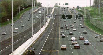
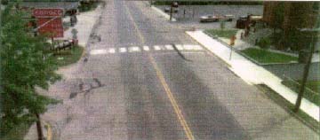
Another option that aids designers in the details of crosssection elements
is the use of computerimaging technology. The series of figures on the following
page illustrates the application of various combinations of basic design elements
to define a number of widening options for a portion of State Highway 23 in
Rockville, MN. These options include the use of different median types and widths
and incorporate different levels of rightofway acquisition.
The Minnesota DOT has found the use of such computerimaging techniques to be
particularly useful in illustrating the impact of alternative design concepts
on existing facilities for project area residents and businesses. Minnesota
DOT has made this approach a standard element in all major project planning
and preliminary engineering assignments.
With the increasing need to ensure meaningful and continuous public involvement
on all such projects, the use of computer imaging to illustrate design alternatives
to communities will help to alleviate potential conflicts and misunderstandings
and lead to the best design decisions.
|
Computer visualization showing proposed design concepts
of SH 23 in Rockville, MN.
Existing conditions.
|
 |
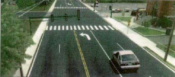
|
Proposed continuous left turn lane design.
|
 |
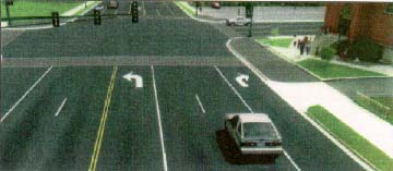
|
Proposed continuous left and rightturn lane design.
|
 |
|
Proposed channelized and raised median design.
|
 |
|