SECTION II: CHAPTER 1
PERSONAL SAMPLING FOR AIR CONTAMINANTS
Contents:
- Introduction
- How to Order Sampling Media
-
General Monitoring Requirements and Guidelines
- Field Blanks
- Total Dust
- Respirable Dust
- Crystalline Silica
- Metals Sampling
- Asbestos
- Organic Vapors and Gases
- Sampling and Analytical Error
-
Soils Analysis in Support of the Excavation Standard
- Custom Services Provided by SLTC
- Bibliography
Appendix II: 1-1. Sampling Pump Calibration
Appendix II: 1-2. Pre-weighed Filters
Appendix II: 1-3. Shelf Life of Sampling Media Provided by the SLTC
Appendix II: 1-4. Partial List of Substances for Gravimetric Determination
Appendix II: 1-5. Cyclone Assembly and Cleaning Instructions
Appendix II: 1-6. Chain of Custody
Appendix II: 1-7. How to Apply Form OSHA-21 to Charcoal Tubes and Filter
Cassettes
Appendix II: 1-8. Completed Air Sampling Worksheet Form OSHA-91A
Appendix II: 1–9. Completed Soil Sampling Worksheet on a Form OSHA–91A
- Introduction
This chapter provides basic information related to sampling air contaminants.
These instructions are essential for acquiring documented and valid exposure
data that will be defensible in the event of contested citations.
This chapter is one of a number of references for sampling air contaminants.
Other reference resources that should be routinely consulted are OSHA's Chemical
Sampling Information (CSI) file and the OSHA Field Inspection Reference Manual
(FIRM). The FIRM identifies CSHO responsibilities associated with the majority
of their inspection duties. OSHA and National Institute for Occupational Safety
and Health (NIOSH) validated sampling and analytical methods should be reviewed,
and when necessary, the Salt Lake Technical Center (SLTC) analytical staff
should be consulted. It is extremely important that SLTC-approved sampling
procedures or procedures described in the CSI that have been approved by the
SLTC be used.
OSHA sampling and analytical methods were developed to provide OSHA with
validated methods to monitor workplace exposure to a wide variety of chemical
substances. These methods were validated with the use of evaluation guidelines
that are published on OSHA's website. The guidelines define sampling and
analytical parameters, specify required laboratory tests, statistical
calculations, criteria for acceptance, and provide a detailed outline for the
written reports. The overall goal of these guidelines is to provide OSHA with
sampling and analytical methods that can be clearly defended with evaluation
data. These sampling and analytical methods were designed and tested for
internal use by OSHA personnel. The use of nonstandard sampling methods may
require resampling with a SLTC-approved sampling procedure. The SLTC is aware
that unique sampling situations will arise during some inspections and close
coordination with the laboratory will provide the best analytical service.
Sampling strategies should be planned for a meaningful evaluation of air
contaminants and prudent use of limited resources. Screening techniques and
devices, such as detector tubes and direct-reading meters may, provide valuable
information when their use and their detection limits are appropriate (see
Section II: Chapter 3 Technical Equipment: On-Site Measurements). Knowledge of
sampling requirements such as sampling media, recommended air volumes, and
sample storage precautions are essential in planning proper sampling strategies.
Bulk samples are sometimes necessary to support analyses of air samples and to
document the source of air contaminants. They are required for certain analyses
such as explosibility and flash point testing. They are sometimes used in Hazard
Communication inspections (i.e., Material Safety Data Sheet (MSDS) compliance).
Consult OSHA's Chemical Sampling Information file to determine when bulk samples
are appropriate. Bulk samples often require special shipping and handling.
Ensure that appropriate sample shipping and handling requirements are followed
(see Chapter 4, Sample Shipping and Handling) and that the mode of shipment is
appropriate for the requested analytical service. For example, "Rush Analysis"
requires sample shipment with overnight delivery. If samples are for "Rush
Analysis," then concurrence by the Area Director is required. Follow all
chain-of-custody protocols and make certain that samples are properly documented
on the Air Sampling Worksheet Form OSHA-91A (see Figures II: 1-24 and II:1-25
for a completed Form OSHA-91A) and properly sealed with Form OSHA-21 as shown in
Appendix II:1-6. Apply the Form OSHA-21 in such a manner that the
chain-of-custody information is not obstructed.
- How to Order Sampling Media
OSHA personnel can order sampling media from the SLTC using the order form
located on the OSHA limited access Intranet under CSHO Resources. Charcoal
tubes, asbestos pre-assembled filters and cassettes, Form OSHA-21 seals,
cyclones, and mixed cellulose ester filters (MCEF) should be ordered from the
Cincinnati Technical Center (CTC).
The SLTC provides pre-weighed filter/cassette units for gravimetric sampling and
analysis to OSHA personnel. The filters are weighed at the SLTC and shipped to
the field assembled in special cassettes to be used for sampling. The
cassette/filter units are returned to the SLTC after sampling for gravimetric
determinations and for other analyses. Refer to OSHA's Chemical Sampling
Information file or to Appendix II:1-4 of this document for a list of analytes
in this category.
- General Monitoring Requirements and Guidelines
A. Documentation
It is essential that accurate and complete sampling pump calibration records and
field sampling notes be recorded on Form OSHA-91A (Air Sampling Worksheet),
which also serves as a sample submission document for samples requiring analysis
by the SLTC. Be sure to use designated sample media to perform pre/post
calibration. Do not use the same media for calibration and field sampling. SLTC
chemists sometimes use sampling pump calibration data to verify air sample
volumes. Detailed line-by-line instructions for completing this document are
given in Chapter XXI (Air Sampling Worksheet, Form OSHA-91A) of OSHA Instruction
IRT 01-00-007 (previously ADM 1-1.31) (The IMIS Enforcement Data Processing
Manual for use with the NCR Computer System). Ensure that handwritten
information is printed legibly. Accurate and consistent spelling of the
inspected establishment name will facilitate future database searches. A
completed Form OSHA-91A (Air Sampling Worksheet) is shown in Figure II: 1-24 and
Figure II:1-25 of Appendix II 1-8 in this document.
Diffusive samplers are convenient air sampling devices that sample gases and
vapors and do not require the use of a sampling pump. OSHA diffusive sampling
methodology exists for only a few chemicals. Refer to the Chemical Sampling
Information file and the ORGANIC VAPORS AND GASES section of this document for
diffusive sampling applications and guidance. When using diffusive samplers,
record the sampling site temperature and pressure on the Form OSHA-91A (Air
Sampling Worksheet). The barometric pressure for the time period sampled can
sometimes be obtained by calling the local weather station or airport or by
accessing National Oceanic and Atmospheric Administration information on the
Internet. If air pressures are obtained by these means, it is necessary to
obtain the unadjusted barometric pressure (station pressure) for compliance
applications.
Take photographs (as appropriate) and detailed notes concerning visible airborne
contaminants, work practices, potential interferences, workplace movements, and
other conditions to assist in determining appropriate engineering controls.
Ventilation and/or smoke tube measurements may also be helpful. Be certain to
observe if the employees wore the sampling equipment properly. This is sometimes
an important issue in litigation. Refer to the FIRM for a more thorough
discussion of inspection documentation procedures.
B. Sampling Protocol
Determine as soon as possible after the start of the inspection whether
full-shift air contaminant sampling is required by using the information
collected during the walkaround (including any screening samples) and from the
pre-inspection review. To eliminate errors associated with fluctuations in
exposure, conduct representative full-shift sampling for air contaminants when
determining compliance with an 8-hour Time-Weighted Average (TWA) Permissible
Exposure Limit (PEL). Full-shift sampling is defined as a minimum of the total
time of the shift less 1 hour (e.g., 7 hours of an 8-hour work shift or 9 hours
of a 10-hour work shift). Make every attempt to sample as much of the work shift
as possible and include segments of greatest exposure during the sampling
periods. However, no more than 8 hours of sample can be used in the 8-hour TWA-PEL
calculation (refer to discussion on
extended work shifts below). A
representative exposure sample period may be less than seven hours; however, the
final analytical result and associated calculation could still result in
non–compliance when averaged over 8 hours.
Extended Work Shifts: Compliance officers can choose one of two approaches for
employees who work extended work shifts beyond 8 hours. The choice taken will
depend on the nature of the hazardous chemical and the work activity being
performed.
- The first approach is to sample what the compliance officer believes to be
the worst continuous 8-hour work period of the entire extended work shift.
- The second approach is to collect multiple samples over the entire work
shift. Sampling is done so that multiple personal samples are collected during
the first 8-hour work period and additional samples are collected for the
extended work shift. Unless a compliance officer is dealing with lead, the
employee’s exposure in this approach is calculated based upon the worst 8-hours
of exposure during the entire work shift. Using this method, the worst 8–hours
do not have to be contiguous. Example: for a 10-hour work shift, following
established sampling protocol as per the CSI file, ten 1-hour samples or five
2-hour samples could be taken and the eight highest 1-hour samples or the four
highest 2-hr samples could be used to calculate the employee's 8-hour TWA, which
would be compared to the 8-hour TWA-PEL.
At the time of this revision, the lead standards for construction and general
industry are the only standards that require PEL adjustments with respect to
extended work shifts.
To reduce their level of exposure, the occupational exposure to the Cotton Dust
standard,
29 CFR 1910.1043, has a requirement to adjust extended work shifts
when employees are required to wear respirators for a portion of the work shift.
The following guidance provides an overview of the sampling process:
- Select the employees to be monitored and discuss the purpose of sampling.
Inform the employees of when and where the sampling equipment will be removed.
Stress the importance of not removing or tampering with the sampling equipment.
Instruct the employees to notify their supervisor or the CSHO if the sampler
requires temporary removal.
When assembling air sampling filter cassettes, it is crucial to verify that the
two halves of the cassette are firmly and completely seated against each other
to prevent sample material from bypassing the filter. Do not mix brands of
cassette components. A hand press can be used to ensure a good seal between the
filter and the cassette halves. Examine the assembled cassette to make certain
that the joints fit together securely. Use shrink tape around the cassette to
cover joints.
- Place the calibrated sampling equipment on the employee so that it does not
interfere with work performance or safety of the employee. Attach the collection
device (filter cassette, charcoal tube, etc.) to the shirt collar or as close as
practical to the nose and mouth of the employee's breathing zone (i.e., in a
hemisphere forward of the shoulders within a radius of approximately nine
inches). The inlet should be oriented in a downward vertical position to avoid
gross contamination from airborne debris. The length of the tubing connecting
the collection device to the sampling pump should not be excessive and it should
be secured to the employee. This will help to prevent the tubing from being
snagged or from interfering with the employee's job function. The inlet (vortex
finder) for a cyclone should be oriented so that it faces away from the
employee. The practice of placing the sampling devices inside personal
protective equipment (PPE) applies only to PPE that is not intended to provide
respiratory protection such as welding helmets. This sampling is performed to
determine if respiratory protection is needed. Sampling outside of the PPE is
used to determine if the correct assigned protection factor is being applied. If
the PPE has supplied air, such as a welding hood or an abrasive blasting hood,
then the sample is placed outside the PPE.
- Turn on the sampling pump and record the start time (time on) on the Form
OSHA-91A (Air Sampling Worksheet). After starting, observe the pump operation
for a short time to make sure that it is operating correctly.
- Record the information required on the Form OSHA-91A, including the sampling
site temperature and pressure for diffusive samplers. Be sure to print legibly
on all forms.
To ensure that a potential exposure level is effectively measured with respect
to a specific regulatory standard, strive to sample for at least the minimum
sampling time/air volume prescribed in the OSHA Chemical Sampling Information
file when a minimum time is listed. Exceptions to this guideline would be when
overloading of the sampling medium is anticipated or observed during sampling.
Overloading is characterized by saturation of the sampling medium. In the case
of filters, overloading may be evidenced by the presence of loose material in
the filter cassette and/or by a reduction in the sampling pump flow rate. For
adsorbent media, overloading occurs when the ability of the sampling medium to
effectively collect the analyte is compromised. In practice, overloading is
difficult to detect and CSHOs should use their observations, experience, and
professional judgment to avoid this adverse sampling situation.
- Periodically monitor the employee throughout the workday to ensure that
sample integrity is maintained and cyclical activities and work practices are
identified. Do not enter areas where sampling is being conducted without the
appropriate personal protective equipment. Frequent pump checks may be
necessary, especially when heavy filter loading is possible. For air sampling
filters, verify symmetrical deposition of particulate on the filter and the
absence of unexpected large particles, or any evidence of tampering with the
sample or pump. Ensure that the sampler remains properly assembled and that the
hose does not become pinched or detached from the sampling device or from the
pump. Record any relevant observations. Turn off or remove sampling pumps
immediately prior to an employee leaving a potentially contaminated area (such
as when he/she goes to lunch or on a break in a clean area). If these areas also
appear contaminated and are considered part of the workplace, continue sampling
and assess the need for surface contamination measurements (see also Section II,
Chapter 2, Occupational Skin Exposure, Biological Monitoring and Surface
Contamination (Wipe) Sampling). If the pump is turned on and off during the
course of the day and if the sampling media is not changed, record subsequent
times (time on/time off) on the Form OSHA-91A (Air Sampling Worksheet).
- Before removing the pump at the end of the sampling period and if the pump
has a rotameter, check the pump to ensure that the rotameter ball is still at
the calibrated mark. If the ball is no longer at the mark, record the pump
rotameter reading.
- Turn off the pump and record the stop time (time off) on the Form OSHA-91A
(Air Sampling Worksheet).
- Remove the collection device from the pump, cap or otherwise close the
sampler, and seal it with a Form OSHA-21 as soon as possible. The seal should be
attached across the sample inlet and outlet so that evidence of any tampering is
visible (see Figures II:1-19, II:1-22, and II:1-23.) Figures II:1-20 and II:1-21
are illustrations of incorrect application of Form OSHA-21 seals. Press the seal
onto the cassette to ensure that the adhesive adheres firmly to the sampling
media surface. Samples with seals that can be removed without obvious evidence
of tampering will be identified as "Proper seals not in place" in SLTC reports
of analytical results.
- Indicate on the Form OSHA-91A if analytical results are to be reported as TWA
results calculated using the actual time sampled or if they are to be reported
as "8-hour TWA" results calculated using zero exposure for non-sampled time
portions of the 8-hour period. OSHA TWA-PELs are defined as 8-hour TWA
exposures. Record results of post-calibration for all pumps used on the
OSHA-91A.
- Prepare the samples for transport to the SLTC for analysis. Submit bulk
samples and air samples separately to avoid cross-contamination. If any
submitted materials could be considered hazardous, consult and follow
appropriate shipping regulations to assure safe handling during shipment (See
Section II, Chapter 4 or contact the SLTC for instructions). Pack the samples
securely in a box or other sturdy container to avoid any rattle or shock damage.
For asbestos samples, do not use expanded polystyrene packing (Styrofoam™) or
other static producing packaging material. Place samples in a plastic bag so
that they do not move freely. Use bubble sheeting or other material as packing.
Put identifying paperwork in every package. Do not send samples in unpadded
envelopes. Make sure that you include a copy of Form OSHA-91A (Air Sampling
Worksheet) with the samples.
- Field Blanks
Blank samples are required for each requested analysis, and for each lot number
of sampling media. Prepare field blanks during the sampling period for each type
of sample collected. One field blank will usually suffice for up to 20 samples
for any given analysis/sampling period except for asbestos, which requires a
minimum of two field blanks, even for a single asbestos sample. Field blanks
(e.g., charcoal tubes, filters) should be opened in the workplace but not used
to take samples. They should be handled, stored, and shipped in the same manner
as other sampling media used in sampling air contaminants, with the exception
that no air is drawn through them. Diffusive samplers should be briefly opened
in the field in an area on-site where no contamination is expected and then
immediately resealed with manufacturer's materials. Diffusive samplers begin to
sample as soon as they are opened and continue to sample until they are sealed.
Follow sample seal procedures for the field blanks.
- Total Dust
Collect total dust samples using pre-weighed polyvinyl chloride (PVC) filters at
a maximum flow rate of 2 liters per minute (L/min) for a maximum sampling time
of 480 minutes or 8 hours. Be careful not to overload the filter. See the
discussion on filter overloading in Section III. GENERAL MONITORING REQUIREMENTS
AND GUIDELINES, SAMPLING PROTOCOL section of this document.
- Respirable Dust
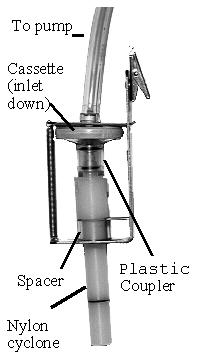
Collect respirable dust samples using a clean Dorr-Oliver cyclone and a
pre-weighed PVC filter at a flow rate of 1.7 L/min for a maximum sampling time
of 480 minutes (see Figures II: 1-1, II:1-2, and Appendix II Figure II: 1-18).
Appendix II: 1–5 contains cyclone assembly and cleaning instructions. Be careful
not to overload the filter. Make certain that the cyclone inlet (vortex finder)
faces away from the person being monitored.
FIGURE II: 1-1.
MSA CYCLONE HOLDER
WITH MSA CASSETTE
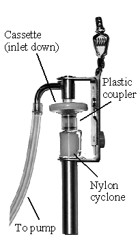 |
FIGURE II: 1-2.
BENDIX CYCLONE HOLDER
WITH MSA CASSETTE
 |
- Crystalline Silica
A. Air Samples
When exposed to silica during abrasive-blasting, air sampling should be done
outside the abrasive–blasting hood.
A respirable silica sample collected without a cyclone is a total dust (or
nonrespirable) sample and different OSHA PELs apply to respirable and total dust
samples. Because of analytical difficulties, CSHOs are discouraged from
submitting total dust air samples for silica analysis. SLTC’s silica analysis
requires that the particle size distribution of the samples be matched as
closely as possible to calibration standards, and this is best accomplished with
a respirable sample. If the collected sample is nonrespirable, the SLTC must be
advised on the Form OSHA-91A (Air Sampling Worksheet).
Contact the SLTC if cristobalite or tridymite analysis is required. In general,
cristobalite and/or tridymite are produced under conditions of high temperature
firing of quartz.
X-ray diffraction (XRD) is the preferred silica analytical method because of its
sensitivity, its minimum requirements for sample preparation, and its ability to
identify polymorphs (different crystalline forms) of free silica. Quartz is
initially identified by its major (primary) X-ray diffraction peak. If
significant levels of quartz are identified, its presence is confirmed using
secondary, tertiary, and/or quaternary peaks to eliminate the possibility of
interfering crystalline substances. CSHOs should notify the SLTC if any of the
following substances are present in the workplace:
Aluminum phosphate
Feldspars (microcline, orthoclase, plagioclase)
Graphite
Iron carbide
Lead sulfate
Micas (biotite, muscovite)
Montmorillonite
Potash
Sillimanite
Silver chloride
Talc
Zircon (Zirconium silicate)
SLTC results for silica air samples are usually reported under one of four
categories:
- Percent quartz and/or percent cristobalite present in the respirable sample.
The analysis of tridymite is performed only when requested and results are
qualitative only.
- Less–than or equal–to (≤) the percent quartz (and/or cristobalite or
tridymite). Less than or equal to values are used when the adjusted 8-hour
exposure is found to be less than the PEL, based on the sample's primary
diffraction peak. The value reported represents the maximum amount of quartz (or
cristobalite) that could be present. However, the presence of quartz (or
cristobalite) was not confirmed using secondary and/or tertiary peaks in the
sample because the sample results did not show a violation of the PEL.
- Approximate Values in Units of Percent. The particle size distribution in a
total dust sample is unknown and error in the XRD analysis may be greater than
for respirable samples. Therefore, for total dust samples, an approximate result
is given.
- Nondetected. A sample reported as nondetected indicates that the quantity of
quartz (or cristobalite) present in the sample is not greater than the detection
limit of the instrument. The detection limit is usually 10 micrograms (µg) for
quartz and 30 µg for cristobalite. If less than a full-shift sample was
collected, CSHOs should evaluate a nondetected result to determine whether
adequate sampling was performed. If the presence of quartz (or cristobalite) is
suspected, CSHOs may want to sample for a longer period of time to increase the
amount of sample collected.
B. Bulk Samples
Bulk samples should be submitted for all silica analyses, if possible. Submit as
much sample as will fit in a 20-milliliter (mL) scintillation vial. Bulk samples
have the following purposes:
- To confirm the presence of quartz (cristobalite and/or tridymite) in the
workplace or to assess the presence of other substances that may interfere in
the analysis of respirable samples.
- To determine the approximate percentage of quartz (cristobalite and/or
tridymite) in the bulk sample.
- To support the evaluation of Material Safety Data Sheets (MSDSs). See comment
on page two above.
- A bulk sample must be representative of workplace dust if the material is to
be used to chemically resolve interferences that cannot otherwise be resolved.
SLTC's order of preference for bulk samples for an evaluation of personal
exposure is:
- A representative settled-dust (rafters, top of equipment, window sills, etc.)
sample.
- A bulk sample of the raw material used in the manufacturing process is
typically analyzed after evaluating MSDSs.
The type of bulk sample submitted to the SLTC should be stated on the Form
OSHA-91A (Air Sampling Worksheet) and be cross-referenced to the appropriate air
samples. Normally, any reported results for bulk sample analysis for quartz (also
cristobalite) will be approximate because of the difficulty in matrix and
particle size matching of the bulk material with the calibration standards used
during analysis.
C. Sample Calculations for Crystalline Silica Exposures
Construction and Shipyard PELs for silica are measured in units of "millions of
particles per cubic foot" (mppcf). To convert analytical results for a
respirable dust measurement to mppcf, use the following formula: mppcf =
((mg/m3)/(0.1)). SLTC's Sampling and Analytical Error (SAE) must be applied to
mg/m3 (milligram per cubic meter) sample results before conversion to mppcf.
Where the employee is exposed to combinations of silica dust (i.e., quartz and
cristobalite), the additive effects of the mixture will be considered.
For the PEL calculation specified in 29 CFR 1910.1000, Table Z-3, the percent
silica will be determined by doubling the percentage of cristobalite and adding
it to the percentage of quartz, according to the formula in Step 2 of the
discussion below. The PEL mixture pertains to the respirable concentration (see
Table 1, Sample Silica Exposure Data).
Example: Two consecutive samples were collected to monitor the same employee for
a combined exposure to silica dusts for one work shift. The analytical results
are shown in Table 1, Sample Calculation for Silica Exposure.
Table 1
SAMPLE SILICA EXPOSURE DATA
|
Sample
|
Sampling
period
(min)
|
Total
volume
(L)
|
Respirable
weight
(mg)
|
Respirable
concentration
(mg/m3)
|
SLTC
results
(%)
|
| A |
238 |
405 |
0.855 |
2.1 |
5.2 quartz
2.3 cristobalite
ND tridymite |
| B |
192 |
326 |
0.619 |
1.9 |
4.8 quartz
1.7 cristobalite
ND tridymite |
| |
|
|
|
|
|
| Total |
430 |
731 |
1.474 |
|
|
Key: ND = Not detectable.
|
|
Calculation of the TWA from the sampling and analytical data:
Step 1. Calculate the percentage of quartz, cristobalite, and tridymite in the
respirable particulate collected.
Quartz: 5.2 (0.855/1.474) + 4.8 (0.619/1.474) = 3.0 + 2.0 = 5.0%
Cristobalite: 2.3 (0.855/1.474) + 1.7 (0.619/1.474) = 1.3 + 0.7 = 2.0%
Step 2. Calculate the PEL for the mixture.
|
PELmixture= |
10mg/m3
------------------------------------------------ |
| % quartz + 2 (% cristobalite) + 2 (% tridymite) + 2 |
| |
|
| = |
10
------------------- |
= |
10
------- |
= 0.91 mg/m3 |
| 5.0 + 2(2.0) + 2(0) + 2 |
11.0 |
| |
|
Step 3. Calculate the employee's exposure. NOTE: 1L = 0.001 m3
|
Exposure = |
Sample wt. A + Sample wt.
B
------------------------------ |
= |
(0.855 +
0.619)/0.731 = 2.0 mg/m3 |
| Total Volume |
Step 4. Adjust (where necessary) for less than 8-hour sampling period.
TWA = (2.0 mg/m3)[(430 min)/(480 min)] = 1.8 mg/m3
Step 5. Calculate the severity of the exposure. Sampling and Analytical Error (SAE)
is applied to analytical results after Step 5. See
Section V:
SAMPLING AND ANALYTICAL ERROR section of this document.
(1.8 mg/m3)/(0.91 mg/m3) = 2.0
- Metals Sampling
A. Air Samples
Collect metal fumes using a three-stage 37-millimeter (mm), 0.8-micrometer (μm)
mixed cellulose ester filter (MCEF) cassette. Use pre-weighed PVC filters for
those substances listed in Appendix II:1-4. See OSHA’s Chemical Sampling
Information file for appropriate sampling rates and times. Be careful not to
overload the filter. See the discussion on filter overloading in the GENERAL
MONITORING REQUIREMENTS AND GUIDELINES, SAMPLING PROTOCOL section of this
document.
When sampling for welding fumes, the filter cassette must be placed inside the
welding helmet to obtain an accurate measurement of the employee's exposure.
Welding fume samples are normally taken using a 37-mm MCEF and cassette. If
these cassettes will not fit inside the helmet, 25-mm MCEF and cassettes can be
used. Extra care must be taken not to overload the smaller 25-mm MCEF when
sampling.
NOTE: The practice of placing the sampling device inside personal protective
equipment (PPE) applies only to PPE that is not intended to provide respiratory
protection such as welding helmets or face shields. This sampling is performed
to determine if respiratory protection is needed. If the PPE has supplied air,
such as a welding hood or an abrasive blasting hood, then the sample is placed
outside the PPE.
B. Bulk Samples
Bulk samples are sometimes taken to document the source of the material present
in the air. Always attempt to take representative samples for bulk analysis.
SLTC analysts will make a reasonable attempt to homogenize samples submitted by
CSHOs, however, excessive sample quantities and highly non-homogenous samples
complicate this process. Ideally, bulk samples should contain a minimum of
approximately 200 mg, but less than a gram, shipped in glass 20-mL scintillation
vials with Polytetrafluroethylene (PTFE) lined caps. However, it is recognized
that these recommended limitations may not always prove practical, and the
professional judgment of the CSHO always takes precedence.
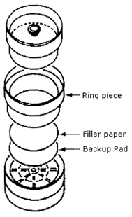
FIGURE II: 1–3. EXPLODED VIEW OF A 37-mm THREE-PIECE CASSETTE AND
ASSEMBLY ILLUSTRATING PLACEMENT OF THE BACK–UP PAD
C. Metal Analysis
The SLTC is capable of analyzing a variety of metals in specific compatible
combinations depending on the ability of the analytical method to simultaneously
dissolve the metals of interest in a given acid matrix. Some of the current
analyte/matrix combinations are listed below and are defined by specific OSHA
sampling and analytical methods. Refer to OSHA’s Chemical Sampling Information
file for the most up-to-date analyte/method combinations.
The following combination of 13 metal analytes can be analyzed simultaneously by
Inductively Coupled Plasma (ICP) using OSHA Method 125G.
Antimony
Beryllium
Cadmium
Chromium
Cobalt
Copper
Iron
Lead
Manganese
Molybdenum
Nickel
Vanadium
Zinc
NOTE: The above combination of analytes has been historically referred to as
"ICP" for welding fume samples. Where one or more of the analytes are requested
for a given filter sample, a full ICP analysis may be conducted, however, CSHOs
should specify metals of the most interest in the event samples cannot be
analyzed by this method or any other multi-element method. Sometimes,
alternative types of samples (e.g., samples taken during abrasive blasting
operations) may not be analyzed using OSHA Method 125G (ICP) because of
analytical difficulties encountered with sample characteristics, heavy sample
loadings, analyte solubility limitations, and instrumental limitations. Some of
these problematic samples and analytes can sometimes be analyzed using other
multi-element methods listed below or with one of the OSHA Method 121 procedures
originally designed for individual metal determinations (e.g., Pb, Cd, Fe).
Refer directly to OSHA Method 121 to interpret the complex choices and
compatibilities of a host of assorted analytes and their various preparation
techniques. When questions of analytical capabilities arise, CSHOs are
encouraged to contact SLTC spectroscopy experts for further guidance and
discussion of analytical options to suit specific compliance monitoring needs.
The SLTC can also analyze the following combination of metal analytes
historically referred to as "solder " using OSHA Method 206:
Antimony
Beryllium
Cadmium
Copper
Lead
Silver
Tin
Zinc
The following combination of metal analytes can be analyzed by OSHA Method 105:
Arsenic
Cadmium
Copper
Iron
Lead
Zinc
The following combination of metal analytes can be analyzed by OSHA Method 1006 (air samples only):
Arsenic
Cadmium
Copper
Cobalt
Lead
Nickel
- Asbestos
Collect samples for asbestos using 0.8-µm, 25-mm diameter MCEF cassettes which
have been specially designated by the manufacturer for asbestos analysis. The
filters must be contained in an electrically conductive cassette assembly that
includes a 50-mm extension cowl (see Figure II: 1-23). Ensure that the bottom
joint (between the extension and the conical black piece) of the cassette is
sealed tightly with a shrink band or electrical tape. Make certain that the
cassette does not leak. Position the open face of the cassette down to minimize
contamination.
Use a flow rate in the range of 0.5 to 5 L/min. One liter per minute is
suggested for general sampling. For office environments, use flow rates of up to
5 L/min. Do not use nylon or stainless steel adapters if in-line calibration
(Figure II: 1-10 and Figure II: 1-12) is done. Do not use the same filter
cassette intended to be used for field sampling for sampling pump calibration.
Sample for as long a time as possible without overloading (obscuring) the filter
because overloading can lead to an unreadable sample (see the discussion on
filter overloading in the
GENERAL MONITORING REQUIREMENTS AND GUIDELINES,
SAMPLING PROTOCOL section of this document). Instruct the employee to avoid
knocking the cassette and, if possible, to avoid using a compressed–air source
that might dislodge the collected contaminant while sampling.
Approximately 10% of all samples submitted should be blanks, with a minimum of
two blanks in all cases.
Where possible, collect and submit a bulk sample of the material suspected to be
in the air. Submit approximately 0.5 to 1 gram of material in a glass
scintillation vial with a PolySealTM cap. Place each bulk sample in a separate
vial. Ship bulk samples and air samples separately to avoid cross-contamination.
Analysis of asbestos air samples is performed by phase contrast microscopy. Bulk
samples are analyzed by polarized light microscopy.
For unusual sampling conditions or high flow rates, contact the SLTC for more
detailed instructions.
- Organic Vapors and Gases
A. Solid Sorbent Sampling Tubes
Organic vapors and gases can be collected using several different sampling media
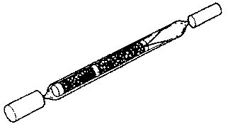
including charcoal sampling tubes (see Figure II: 1-4) with low-flow sampling
pumps. Refer to OSHA's Chemical Sampling Information file for required sampling
media, sampling rates, and sampling times for specific chemicals. Sampling rates
may need to be reduced or smaller air volumes (half the maximum) sampled when
the humidity is greater than 90% or when relatively high concentrations of other
organic vapors are present. Calibrate the sampling pump as stated and shown in
Appendix II: 1-1.
FIGURE II: 1-4. CHARCOAL TUBE WITH FLAME-SEALED ENDS AND END CAPS
Immediately before sampling, break off the ends of the flame-sealed tube to
provide an opening approximately half the internal diameter of the tube. Wear
eye protection when breaking ends, and be careful not to cut yourself. Do not
use the charging inlet or the exhaust outlet of the pump to break the ends of
the tube. When possible, always use tube holders to shield the sampled person
from the sharp ends of sampling tubes.
The smaller section of the sampling medium is the back–up section and it should
be positioned closest to the sampling pump. If directional arrows are present on
the sampling tubes, point the arrow towards the pump. The tube should be held or
attached in an approximately vertical position during sampling. Draw air to be
sampled directly into the inlet of the tube. Generally, this air is not to be
passed through any hose or tubing before entering the tube except in cases where
a short piece of tubing is used to protect the end of the sampling tube (e.g.,
use of two tubes in series).
Cap the tube with the supplied plastic caps immediately after sampling and seal
the tube with a Form OSHA-21 as soon as possible (see Figure II:1-19). The Form
OSHA-21 should cover the end caps. If the seal does not cover the end caps, tape
the ends of the seal, using clear plastic tape so that it is secure and
tamper-resistant. Do not ship air samples with bulk samples.
B. Diffusive (Passive) Sampling
Diffusive samplers (also known as passive monitors or badges), Figure II:1-5,
are useful for compliance monitoring. The major advantage of diffusive sampling
is that no sampling pump is required. Some diffusive samplers and analytes have
been validated for compliance sampling and they are shown in Table 2. Some
analytes other than those shown below may be identified and quantitated by the
SLTC, but these analytical results are usually reported as "approximations" and
should be used only for screening purposes. Temperature and barometric pressure
at the sampling site must be provided by the CSHO for proper calculation of
exposure results for diffusive samplers. The barometric pressure for the time
period sampled can sometimes be obtained by calling the local weather station or
airport or by accessing NOAA information on the Internet. If air pressures are
obtained by this means, it is necessary to obtain the unadjusted barometric
pressure (station pressure) for compliance applications. Results from samples
without sampling site temperature and pressure will have significantly higher
Sampling and Analytical Error values. Specific sampling instructions for each
type of diffusive sampler are supplied with the sampler and in OSHA methods that
permit diffusive sampling. Diffusive samplers should not be opened until just
before sampling because they begin to sample as soon as they are opened. To
terminate sampling, properly seal the samplers with the manufacturer's packaging
materials. Send the sealed sampler and all its accessories to the SLTC for
analysis. Interfering substances should be noted on the Form OSHA-91A (Air
Sampling Worksheet). Contact the SLTC for further information regarding
diffusive sampler availability and use. Consult OSHA's Chemical Sampling
Information file for new methods as they become available.
FIGURE II:1-5. DIFFUSIVE SAMPLER
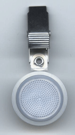
Table 2
OSHA Validated Sampling and Analytical Methods
That Permit Diffusive Sampling
|
| Analyte |
Method |
Sampler |
| benzene |
OSHA 1005 |
SKC 575-002
3M 3520 |
| 2-butanone (MEK) |
OSHA 1004 |
SKC 575-002
3M 3520 |
butyl acetate
(n, iso, sec, tert isomers) |
OSHA 1009 |
SKC 575-002
3M 3520 |
| ethyl benzene |
OSHA 1002 |
SKC 575-002 |
| ethylene oxide |
OSHA 49 |
3M 3551 |
| formaldehyde |
OSHA 1007 |
AT Aldehyde Monitor 571
SKC UMEx 100
Supelco DSD-DNPH |
| hexone (MIBK) |
OSHA 1004 |
SKC 575-002
3M 3520 |
| nitrous oxide |
Kem Medical Products Method |
Kem Vapor Trak
Nitrous Oxide Monitor |
| radon |
ID-208 |
E-Perm |
| tetrachloroethylene |
OSHA 1001 |
SKC 575-002 |
| trichloroethylene |
OSHA 1001 |
SKC 575-002 |
| Thoron |
Contact OSHA SLTC HRT |
E-Perm |
| Toluene |
OSHA 111 |
SKC 575-002
3M 3520 |
| xylene (o, m, p isomers) |
OSHA 1002 |
SKC 575-002
3M 3520 |
C. Impingers and Bubblers
FIGURE II: 1-6. MIDGET IMPINGER AND BUBBLER
|
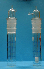 |
Examples of a midget impinger (left side) and of a midget bubbler (right side)
are shown in Figure II:1-6. The term midget refers to the volume of the sampler
flask. The difference between an impinger and a bubbler is that the jet (inlet
tube) of an impinger is tapered and sized to allow sufficient velocity for
particles to strike the bottom of the flask and become suspended in the liquid
while the stem of a bubbler is fritted to allow collection of vapors in the
solution. Bubblers break incoming air into small bubbles to improve collection
efficiency of vapors. The following suggestions should be followed when using
impingers and bubblers.
- Numbers are usually etched into flasks and stems, and matching numbers should
be used whenever possible. Take care in preparing impingers and bubblers so that
tips or frits are not damaged and so that joints can be securely tightened.
- Rinse the impinger or bubbler with the appropriate reagent (see OSHA's
Chemical Sampling Information file). Then add the specified amount of this
reagent to the bubbler or impinger flask. Contact SLTC to obtain these reagents.
- To prevent overflow, do not add more than 10 mL of liquid to midget impingers
or bubblers. Place an empty impinger in series after the impinger (or bubbler)
has been used for sampling. Position this impinger just before the sampling
pump; it can be taped to the pump. If a holster is available, tape the holstered
impinger to the pump. This impinger will function as a trap to collect any
liquid lost from the sampling impinger (or bubbler) so that the sampling pump
will be protected.
- The sampling rate for midget impingers is 2.8 L/min. Collect contaminants in
a bubbler at a maximum flow rate of 1.0 L/min. Because bubblers tend to offer
better collection efficiency than impingers, they are preferred over impingers
for gas and vapor sampling. Impingers are used only when absolutely necessary
for particle counting. Contact SLTC prior to collecting any samples for particle
(dust) counting using impingers.
- The impinger or bubbler can either be hand-held by the CSHO or it can be
attached to the employee's clothing using a holster. In either case, it is very
important that the impinger or bubbler does not tilt and cause the reagent to
flow down the side arm to the hose and into the pump. NOTE: Attach a trap
in-line with the pump, if possible.
- In some instances, it will be necessary to add additional reagent during the
sampling period to prevent the amount of reagent from dropping below one half of
the original amount.
- After sampling, remove the glass stopper and stem from the impinger or
bubbler flask.
- Rinse the absorbing solution adhering to the outside and inside of the stem
directly into the impinger or bubbler flask with a small amount (1-2 mL) of the
sampling reagent. Pour the contents of the flask into a 20-mL glass vial
(preferably a scintillation vial with inert caps and liners). Avoid using metal
cap liners or other materials that may react with the samples.
Polytetrafluoroethylene (PTFE) cap liners with polypropylene caps are inert to
most materials. Rinse the flask with a small amount (1-2 mL) of the reagent and
pour the rinse solution into the vial. Tape the cap shut by wrapping the tape in
the direction of cap closure to prevent it from coming loose due to vibration.
If electrical tape is used, do not stretch the tape too much because it could
shrink and loosen the cap.
D. Gas Sampling Bags and Canister Samplers
OSHA uses gas sampling bags to sample carbon dioxide, carbon monoxide, and
nitrous oxide. CSHOs can obtain gas sampling bags from SLTC. Be certain not to
fill the bag to more than 75% of its rated volume, and to close the sampling
valve after sampling. Place Form OSHA-21 over the valve(s). Transport the gas
sampling bag to SLTC by ground shipment if it contains particularly hazardous
materials or if its odor is particularly offensive.
Gas sampling bags or canisters are sometimes used to collect whole air samples
for forensic-type investigations. Call SLTC for guidance.
- Sampling and Analytical Error (SAE)
All sampling and analytical methods have some degree of uncertainty. The total
uncertainty depends on the combined effects of the contributing uncertainties
inherent in sampling and analysis. Uncertainty in sampling results has
historically been called Sampling and Analytical Error by OSHA. Correct
application of SAE enables CSHOs to make reliable compliance decisions regarding
sample results. SAE is especially important when sample results are near the PEL.
A. Definition of Upper and Lower Confidence Limits
Error factors determined by statistical methods shall be incorporated into the
sample results to obtain the lowest value of the true exposure (with a stated
degree of statistical confidence) and also the highest value of the true
exposure (also with a stated degree of statistical confidence).
Confidence limits are values at each end of the confidence interval, which is
the probable range of the true value. The lower value is called the lower
confidence limit (LCL), and the upper value is the upper confidence limit (UCL).
The LCL and the UCL are each termed one-sided because the main concern is with
being confident that the true exposure is either less or greater than the PEL.
OSHA applies the LCL and UCL with a 95% statistical confidence limit and they
are expressed here as LCL95% and UCL95%.
B. Determining Sampling and Analytical Errors (SAEs)
SAEs that provide a one-sided 95% confidence limit have been developed and are
listed on each Form OSHA-91B (Air Sampling Report) report (most current SAEs).
If there is no SAE listed on the Form OSHA-91B (Air Sampling Report) for a
specific substance, contact the SLTC.
C. Workplace Variables
Differences in sampling results can occur when workplace variables (process
changes, changes in work practices, changing air movement and velocity, etc.)
result in variances greater than sampling and analytical errors. Samples taken
on a given day are used by OSHA to determine compliance with PELs. However, when
the employer has previously monitored the work area, CSHOs should review the
long-term pattern and compare it with their sampling results. When OSHA's sample
results fit the long-term pattern, it helps to support the compliance
determination. When OSHA's results differ substantially from the historical
pattern, CSHOs should investigate and determine the cause of this difference.
D. Confidence Limits
One-sided confidence limits can be used to classify the measured exposure into
one of four categories:
- If the measured exposure exceeds the PEL and the LCL95% of the exposure is
greater than 1.0, the CSHO can be 95% confident that the employer is in
noncompliance, and a violation is established. (See Equation II:1-6F.)
- If the measured exposure exceeds the PEL, but the LCL95% of this exposure is
less than 1.0, the CSHO cannot be 95% confident that the employer is in
noncompliance. (See Equation II:1-6F.)
- If the measured exposure does not exceed the PEL and if the UCL95% of this
exposure is less than 1.0, the CSHO can be 95% confident that the employer is in
compliance. (See Equation II:1-6E.)
- If the measured exposure does not exceed the PEL, but the UCL95% of this
exposure is greater than 1.0, the CSHO cannot be 95% confident that the employer
is in compliance. (See Equation II:1-6E.)
In categories 2 and 4, the measured exposure can be termed a "possible
overexposure."
A violation is not established if the measured exposure is in the "possible
overexposure" category. It should be noted that the closer the LCL95% comes to
exceeding 1.0, the more probable it becomes that the employer is in
noncompliance. If measured results are in this region, the CSHO should consider
further sampling, taking into consideration the seriousness of the hazard and
pending citations.
If further sampling is not conducted, or if additional measured exposures still
fall into the "possible overexposure" category, the CSHO may wish to carefully
explain to the employer and employee representative at the closing conference
that the exposed employee(s) may be overexposed but that there is insufficient
data to document noncompliance. The employer should be encouraged to voluntarily
reduce the exposure and/or to conduct further sampling to ensure that exposures
are not in excess of the PEL.
E. Sampling Methods
The LCL95% and UCL95% are calculated differently depending upon the type of
sampling method used. Sampling methods can be classified into one of two
categories:
- Full-period, Continuous Single Sampling. Full-period, continuous single
sampling is defined as sampling over the entire sample period with only one
sample. The sampling may be for a full-shift sample or for a short period
ceiling determination
- Full-period, Consecutive Sampling. Full-period, consecutive sampling is
defined as sampling using multiple consecutive samples of equal or unequal time
duration that, if combined, equal the total duration of the sample period. An
example would be taking four 2-hour charcoal tube samples. There are several
advantages to this type of sampling:
- If a single sample is lost during the sampling period due to pump failure,
gross contamination, etc., at least some data will have been collected to
evaluate the exposure.
- The use of multiple samples should result in slightly lower sampling and
analytical errors.
- Collection of several samples allows conclusions to be reached concerning the
manner in which differing segments of the work day affect overall exposure.
This practice also allows for monitoring Peak and Ceiling exposures for the
appropriate time.
F. Calculations
If the initial and final sampling pump calibration flow rates are different, use
of the highest of the two calibration flow rates will provide the lowest
analytical results for compliance purposes.
Generally, sampling is conducted at approximately the same temperature and
pressure as calibration, in which case no correction for temperature and
pressure is required and the sample volume reported to the SLTC is the volume
actually measured. Where sampling is conducted at a substantially different
temperature or pressure than calibration, consult the operating manual for the
sampling pump to determine if the air volume needs to be adjusted. If possible,
calibrate the equipment at the site. The air volume reported by the CSHO is used
in all subsequent calculations.
For particulates, the SLTC reports mg/m3 of contaminant using the actual volume
of air sampled at the sampling site as reported by the CSHO. The value in mg/m3
can be compared directly to OSHA PELs for particulates (e.g., 29 CFR 1910.1000).
The SLTC normally does not measure concentrations of gases and vapors directly
in parts per million (ppm). Rather, most analytical methods determine the total
weight of contaminant in the collection medium. Using the air volume provided by
the CSHO, the lab calculates concentration in mg/m3 and then converts it to ppm
at 25°C and 760 mm Hg using Equation II:1-6A. This ppm result is to be compared
with the PEL without adjustment for temperature and pressure at the sampling
site.
Equation II:1-6A
| ppmNTP = (mg/m3)(24.46)/MW |
| |
| where: 24.46 = molar volume at 25°C (298 K) and |
| 760 mm Hg |
|
MW = molecular weight |
|
NTP = Normal Temperature and Pressure |
|
(25°C and 760 mm Hg) |
|
mm Hg = millimeters of mercury |
|
CSHOs will not usually need to calculate the exposure concentration in ppm at
the sampling site (ppmpt) but, if necessary, it can be calculated from SLTC
results reported in ppmNTP by using the following equation:
Equation II:1-6B
| ppmPT = (ppmNTP)(760/P)(T/298) |
| |
| where: P = sampling site pressure (mm Hg) |
| T = sampling site temperature (K) |
| 298 = normal temperature in degrees Kelvin (273 + 25) |
|
Equation II:1-6C
| Because ppmNTP = (mg/m3)(24.46)/(MW) |
| ppmPT = (mg/m3)(24.46/MW)(760/P)(T/298) |
|
NOTE: When a contaminant concentration is converted from mg/m3 and expressed as ppmPT, that value cannot be compared directly to the PEL table without first
converting it to its corresponding ppmNTP value.
NOTE: The barometric pressure for the time period sampled can sometimes be
obtained by calling the local weather station or airport or by accessing NOAA
information on the Internet. If air pressures are obtained by this route, it is
necessary to obtain the unadjusted barometric pressure (station pressure) for
compliance applications. The barometric pressure information most readily
available from weather and aviation sources is the sea-level adjusted barometric
pressure which tends to average about 760 mm Hg and does not represent the
actual air pressure of worksites much removed from sea level.
If the sources above are not readily available or cannot provide the actual
station pressure, then the elevation (Elev) in feet of the worksite can be used
to calculate the typical barometric pressure (P) in mm Hg using the following
equation:
| P |
= |
760 |
[ |
1 |
- |
Elev x 1.6470 x 10⁻³ |
] |
6.3222 |
|
| 295.20 x (1+ Elev x 4.9787 x 10 -8 |
The above equation is an adaptation of the atmospheric model equation used in
the U.S. Standard Atmosphere, 1976 using a higher average effective sea-level
screen temperature (295.20 K) and lower temperature lapse rate (5.4 K/km)
typically observed over land surfaces within the northern latitudes of the U.S.
(19o N to 61o N). For most of the U.S., the barometric pressures obtained with
this equation are better estimates of observed station pressures than the 1976
model, and deviate from mean annual station pressures by about 0.24% RSD
(percent relative standard deviation) for elevations below 4,300 ft. and 0.52%
RSD for elevations below 30,000 ft. These deviations are insignificant compared
to the estimated 1.6% RSD for combined normal seasonal, storm, and diurnal
station pressure variations observed at any elevation within the year. The 1.6%
RSD may be assumed if the worksite elevation can be estimated to within 100
feet. A global positioning system (GPS) elevation measurement is typically
within 100 feet of the actual elevation. GPS elevation measurements should be
made outdoors and away from tall structures. Example calculations using the
equation give 723.2 mm Hg for an elevation of 1,400 ft. above mean sea level and
569.5 mm Hg for an elevation of 8,000 ft. above mean sea level. Due to Alaska's
high latitudes, the equation above is biased high for significant elevations in
Alaska; therefore, the station pressure of a nearby weather station is necessary
to obtain accurate air pressures for most of Alaska.
G. Calculations for Full–Period, Continuous Single Samples
Obtain the full-period sampling result (X), the PEL, and the SAE. The SAE can be
obtained from the Form OSHA-91B (Air Sampling Report) or by contacting the SLTC.
Divide the full-period sampling result X by the PEL to determine the exposure
severity, Y. That is:
Equation II:1-6D
Compute the upper confidence level at the 95% confidence level (UCL95%) as
follows:
Equation II:1-6E
Compute the lower confidence level at the 95% confidence level (LCL95%) as
follows:
Equation II:1-6F
Classify the exposure according to the following classification system:
If the UCL95% < 1.0, a violation does not exist.
If LCL95% < 1.0 and the UCL95% > 1.0, classify as possible overexposure.
If LCL95% > 1.0, a violation exists.
H. Sample Calculations for Full–Period, Continuous Single Sample (Example)
A single glass-fiber filter and personal sampling pump were used to sample for
carbaryl for an 8-hour period. The SLTC reported 6.07 mg/m3. The SAE for this
method is 0.23. The PEL is 5.0 mg/m3.
Step 1. Calculate the exposure severity.
Y = 6.07/5.0 = 1.21
Step 2. Calculate confidence limits.
LCL95% = 1.21 - 0.23 = 0.98
Because the LCL95% does not exceed 1.0, noncompliance is not established. The
UCL95% is calculated:
UCL95% = 1.21 + 0.23 = 1.44
Step 3. Classify the exposure.
Because the LCL95% < 1.0 and the UCL95% > 1.0, classify as possible
overexposure.
I. Calculations for Full–Period Consecutive Samples (Example)
The use of multiple consecutive samples should result in slightly lower sampling
and analytical errors than the use of one continuous sample because the inherent
errors tend to partially cancel each other. The mathematical calculations,
however, are somewhat more complicated. The CSHO should first determine if
compliance or noncompliance can be established using a calculation method
similar to that noted for a full–period, continuous, single sample measurement,
following the instructions in the "Compliance/Noncompliance Method" box below.
If results fall into the "possible overexposure" region using this method, a
more exact calculation should be performed using equation II: 1-6G, below.
Classify the exposure according to the following classification system:
If UCL95% < 1.0, a violation does not exist.
If LCL95%< 1.0, and the UCL95% > 1.0, classify as possible overexposure.
If LCL95% > 1.0, a violation exists.
When the LCL95% < 1.0 and UCL95% > 1.0, the results are in the "possible
overexposure" region and the CSHO must analyze the data using the more exact
calculation for full-period consecutive sampling, as follows:
Compliance/Noncompliance Method
|
- Obtain X1, X2 ... Xn, the n consecutive concentrations in one workshift and
their corresponding time durations in minutes, T1, T2 ... Tn.
|
- Also obtain the SAE listed in the Form OSHA-91B sample report form.
|
- Compute the TWA exposure, X.
|
|
|
|
(X1T1)+(X2T2)...+(XnTn) |
|
|
X |
= |
|
|
|
|
|
480 min |
|
- Divide the TWA exposure by the PEL to find Y, the standardized average (TWA/PEL).
|
- Compute the UCL95% as follows:
|
- UCL95% = Y + SAE (Equation II:1-6E)
|
- Compute the LCL95% as follows:
|
- LCL95% = Y - SAE (Equation II:1-6F)
|
|
Equation II:1-6G
J. Sample Calculations for Full–Period Consecutive Sampling (Example)
If two consecutive samples had been taken for carbaryl instead of one continuous
sample, and the following results were obtained:
| -- Samples -- |
| |
A |
B |
| Sampling rate (L/min) |
2.0 |
2.0 |
| Time (min) |
240 |
240 |
| Volume (L) |
480 |
480 |
| Weight (mg) |
3.005 |
2.808 |
| Concentration (mg/m3) |
6.26 |
5.85 |
|
The SAE for carbaryl is 0.23
Step 1. Calculate the UCL95% and the LCL95% from the sampling and analytical
results:
TWA = ((6.26 mg/m3) (240 min) + (5.85 mg/m3) (240 min))/480 min = 6.055 mg/m3
Y = (6.055 mg/m3)/PEL = 6.055/5.0 = 1.21
Assuming a continuous sample: LCL95% = 1.21 - 0.23 = 0.98
UCL95% = 1.21 + 0.23 = 1.44
Step 2. Because the LCL95% < 1.0 and UCL95% > 1.0, the results are in the
possible overexposure region. To document an overexposure, the CSHO must
reanalyze the data using the more exact calculation for full-period consecutive
sampling as follows:
= 1.21 - 0.20 = 1.01
Since the LCL 95% > 1.0, a violation is established.
K. SAEs for Exposure to Chemical Mixtures
Often an employee is simultaneously exposed to a variety of chemical substances
in the workplace. Additive toxic effects on a target organ are common for such
exposures in many construction and manufacturing processes. This type of
exposure can also occur when impurities are present in single chemical
operations. Permissible exposures for mixtures involve the complex problem of
additive exposures and their health effects. In addition, 29 CFR 1910.1000
contains a computational approach to assess exposure to a mixture. This
calculation should be used when components in the mixture pose an additive
health effect. While these calculations can be used for synergistic exposures, a
separate assessment must be performed. For synergistic mixtures, an
individualized assessment of toxicity using the most current scientific data is
conducted to consider the total physiological burden. (See the
OSHA Field
Inspection Reference Manual (FIRM) for further details). The following is an
intranet site available to OSHA personnel that addresses SAEs for exposure to
chemical mixtures,
Considering Sampling and Analytical Errors (SAEs)
for Exposures to Mixtures.
Whether using a single PEL or the mixture calculation, the sampling and
analytical error (SAE) of the individual constituents must be considered before
arriving at a final compliance decision. These SAEs can be pooled and weighted
to give a control limit for the additive mixture. To illustrate this control
limit, the mixture calculation is expressed in the following equation.
Equation II: 1–6H
| |
|
C1 |
|
C2 |
|
|
|
Cn |
|
| Ymixture |
= |
|
+ |
|
+ |
. . . |
+ |
|
|
| |
|
L1 |
|
L2 |
|
|
|
Ln |
|
| Where: |
| Ymixture = equivalent exposure severity for a mixture |
| (Ymixture should be < 1 for compliance) |
| Cn = concentration of a particular substance |
| Ln = PEL for a particular substance |
|
For example, to calculate exposure to three different but additive substances:
Material
|
8-hour exposure
|
8-hour TWA PEL (ppm)
|
SAE
|
| Substance 1 |
500 |
1000 |
0.089 |
| Substance 2 |
80 |
200 |
0.11 |
| Substance 3 |
70 |
200 |
0.18 |
|
| Using Equation II: |
1-6 H: |
YMixture |
= |
500 |
|
80 |
|
70 |
= |
1.25 |
|
|
+ |
|
+ |
|
| 1000 |
|
200 |
|
200 |
Because the sum of the severities, Ymixture > 1, an overexposure appears to have
occurred, however, the SAE for each substance also needs to be considered:
| Exposure severity ratio (for each substance): |
|
= |
Cn |
|
| Yn |
|
|
| |
Ln |
|
| Ratio each to total exposure: |
R1 = |
Y1 |
, R2 = |
Y2 |
, ... , |
Rn = |
Yn |
|
|
|
|
|
| Ymixture |
Ymixture |
Ymixture |
|
For multiple analytes based on multiple analyses on the same sample use
SAEmixture = SAEH (e.g., where SAEH is the highest SAE of the analytes measured
above the quantitation limit; that provides a more accurate estimate of the
SAEmixture).
For analytes based on independent samples (different samplers), the SAEs (95%
confidence) of the substance comprising the mixture can be pooled to give the
SAE of the mixture using:
The mixture Upper Control Limit (UCLmixture) is equivalent to: Ymixture +
SAEmixture
The mixture Lower Control Limit (LCLmixture) is equivalent to: Ymixture -
SAEmixture
If UCLmixture < 1.0, then an overexposure has not been established at the 95%
confidence level.
If LCLmixture < 1.0, and the UCLmixture > 1.0, classify as possible overexposure
and further sampling may be necessary.
If LCLmixture > 1.0, then an overexposure has occurred (95% confidence).
Using the mixture data above:
| Y1 = 500/1000 |
Y2 = 80/200 |
Y3 = 70/200 |
| Y1 = 0.50 |
Y2 = 0.40 |
Y3 = 0.35 |
| R1 = Y1/Ymixture = 0.40 |
R2 = 0.32 |
R3 = 0.28 |
| SAEmixture = 0.071 |
| |
| LCLmixture = Ymixture - SAEmixture |
| |
| LCLmixture = 1.25 - 0.071 =1.18 |
Therefore, LCLmixture > 1 so an overexposure has occurred within 95% confidence
limits. This calculation is also used when considering a mixture exposure such
as total welding fumes.
- Soil Analysis in Support of the Excavation Standard
Soils analysis at the SLTC is performed to support CSHOs inspection and
compliance responsibilities. It also supports citations and legal proceedings.
A representative soil sample from a trench or excavation is sent to the SLTC for
analysis. Soil should be placed in a heavy-duty and tear-resistant plastic bag,
secured, and sealed with tape to be airtight. Place the first plastic bag in a
second heavy-duty plastic bag for additional protection. Sample size can vary
from one pint for very fine-grained samples to two quarts for coarse gravel. A
typical sample should be approximately one quart and weigh about three pounds.
The Form OSHA-91A should not be put in the bag with the soil.
This soil sample is examined and tested according to OSHA Method ID-194. This
fully validated method was developed specifically for the OSHA Excavation
standard. The required tests take a minimum of four days. SLTC sample results
specify the soil type as well as Textural and Structural Classification. The
Type Classification will be A, B, or C corresponding to the descriptions listed
in the Code of Federal Regulations. When requested, moisture content can also be
provided.
Any questions arising from this analysis can be answered by trained soil experts
at the SLTC. This analysis helps CSHOs as well as the inspected establishment
personnel understand how to properly protect employees from cave-ins and how to
properly evaluate protection measures used to comply with existing regulations.
- Custom Services Provided by SLTC
The following services are available on a case-by-case basis at the SLTC.
Concurrence from your Area Director in an e-mail (or via other means) sent to
SLTC management must be received before SLTC can commit to providing some of
these services.
A. Mass Spectrometry
The mass spectrometry laboratory at the SLTC has a number of unique tools to
help CSHOs resolve difficult field sampling and analytical issues. For example,
mass spectrometry can be used to identify unknown or suspected organic
substances found in industrial processes, low level indoor air quality
complaints and contaminated water. It can also be used to identify secondary
substances that are given off from a heated material.
One of the major functions of the mass spectrometry laboratory is identification
and confirmation of analytes measured in gas chromatography (GC) analysis
performed at the SLTC. The same separation and identification techniques used to
confirm identity of known analytes are also useful to identify an unknown
material, investigate possible contamination or batch uniformity in a material
from an industrial process, or to check for conformity with a Material Safety
Data Sheet.
Volatile organic chemicals in contaminated water can be quantitated by purge and
trap, by equilibrium headspace analysis, or by a novel approach involving
thermal desorption called "Twister." The "Twister" technology is simple to use
and highly sensitive.
Thermal desorption/Gas Chromatograph/Mass Spectrometer (TD/GC/MS) is also useful
for investigation of low-level or transient odors, and indoor air quality-type
complaints. The SLTC can provide sampling tubes containing three resin beds
designed to collect a broad range of volatile analytes. The entire collected
sample is thermally desorbed into the gas chromatographic column, providing
analysis with maximum sensitivity.
Using a device called a direct insertion probe and a technique called pyrolysis,
some thermally labile compounds can be introduced directly into the mass
spectrometer source before heat is applied. With another instrument called a
PyroprobeTM, materials can be heated to temperatures as high as 1400°C, with
subsequent introduction of decomposition products into the GC column. Products
released from materials involved in a fire, heated by a welder or blowtorch, or
from any process involving heating can be studied in this way.
B. Materials Analysis
The SLTC provides a variety of services to determine the cause of materials
failure. Materials failure analysis examines the extent to which the properties
of materials or their use contribute to significant investigations, including
fatalities. This often involves collaboration of experts in multiple disciplines
including metallurgical engineering, materials science, explosibility, and both
inorganic and organic chemistry.
The SLTC has assisted in the investigation of several diverse catastrophes.
These investigations have included chemical, gas, and dust explosions and
disasters caused by incompatible chemicals and processes; metal and plastic
failures; wire, synthetic and natural fiber rope failure; scaffold planking
failure; plastic, fiberglass and metal piping failure; radio tower support
failure; safety equipment failure; and chain and equipment overloading.
SLTC's services include assistance in searching for industry standards that help
support citations, and assistance with finding an accredited laboratory to
perform any analysis that is not done at the SLTC. The SLTC tailors the
assistance to the particular investigation. The SLTC can either arrange to fully
investigate the accident on-site, or to review results from an independent
laboratory.
C. Biological Sampling
In the event that a CSHO believes biological monitoring would be valuable to
assess and evaluate employee exposure to a substance or mixture of substances,
they should first contact their Regional office, SLTC and the Office of
Occupational Medicine to determine the most effective approach and technique to
obtain the desired result. Biological sampling requires special consideration
and will be addressed on a case–by–case basis.
SLTC provides biological (both organism and chemical by-product) sampling and
analysis coordination as a service to CSHOs. The SLTC has developed a standard
operating procedure to assure consistent sample handling and analysis. Samples
collected and analyzed through this procedure are compliant with the SLTC
quality–control system and chain-of-custody requirements. SLTC offers
contracting services for fungi, bacteria, Legionella, and endotoxin analysis.
Other services can be arranged on a case–by–case basis.
Again, before collecting biological samples, CSHOs are requested to contact SLTC
for sampling requirements, technical support, assessment, and analytical
coordination. SLTC staff will review sampling and analysis plans with CSHOs and
make recommendations where appropriate. The purpose of this process is to ensure
that prudent sampling is performed.
D. Explosibility Analysis
Because of the complexity of this field, it is strongly recommended that the
CSHOs contact the SLTC before taking explosibility samples. This allows the
explosibility experts to assist CSHOs in taking appropriate samples, and in
tailoring the analysis to provide support for the specific inspection.
The SLTC provides an assortment of analytical and technical information services
in support of inspections involving potential explosion hazards. Analytical
testing is performed in support of OSHA inspections pertaining to hazardous
classified locations, grain handling, dust collection systems, confined space,
and housekeeping. Informational support is offered for litigation,
interpretation of analytical results (both in-house testing results and results
from contract laboratories), and guidance for sampling and standard
applicability. Explosibility experts can help investigate industrial incidents
involving explosions. This help may include normal explosibility testing, and
research into the reactive nature of the materials in question.
The SLTC can provide analyses for flash points, energetic reactivity of
chemicals, and autoignition temperatures. This testing is useful in support of a
wide variety of inspections.
E. Carboxyhemoglobin Calculations
Carbon monoxide (CO) exposure is determined by calculations based on
post-exposure carboxyhemoglobin (COHb) blood levels provided by non-OSHA medical
professionals. The documented SLTC modifications (printed in the supplemental
report that accompanies sample results) use a more accurate version of the
Coburn, Forster Kane equation than the closed-form version used in the 1972
NIOSH criteria document. The SLTC equation calculates the 8-hour TWA ppm
Recommended Exposure Limit (REL) that would result in a 5% COHb level. Poisoning
cases generally involve levels above 5% COHb. The calculation also provides an
incident-specific SAE designed to deal with the uncertainties in the data. The
calculation is performed at the SLTC and the results are critically assessed for
accuracy by SLTC staff prior to reporting. SLTC carbon monoxide experts are
available to assist CSHOs in acquiring data and in interpreting results.
Following are suggestions to help ensure that the most accurate calculations
will be performed.
- If possible, call one of SLTC's carbon monoxide experts before you go
on-site, especially if methylene chloride is used on-site.
- Before going on-site, download and read the worksheet entitled "Submitting
Data for the Carbon Monoxide Calculation at the OSHA Salt Lake Technical Center
(SLTC)" that is presently available on OSHA's Intranet at "CSHO Resources,
Inspection Preparation, Biological Exposure Assessment." There are additional
SLTC contact persons listed on the worksheet. Take the worksheet on-site.
- Collect vital statistics for victims (age, weight, sex, living or dead).
- Detail smoking activity (first-hand, second-hand tobacco smoke).
- Document oxygen saturation-affecting conditions, such as pre- and
post-exposure activity levels and oxygen therapy.
- Provide accurate timelines.
- List signs and symptoms of suspected exposure.
- Review the document for accuracy and completeness before submitting it to SLTC.
- Bibliography
Fundamentals of Analytical Procedures in Industrial Hygiene, AIHA Publication,
1987.
Hesketh, H.E. Fine Particles in Gaseous Media. Chelsea, MA.: Lewis Publishers,
Inc., 1986.
Lioy, P.J. Air Sampling Instruments for Evaluation of Atmospheric Contaminants.
Cincinnati, OH.: American Conference of Governmental Industrial Hygienists,
1989.
Lodge, J.P., Jr. (Ed.) Methods of Air Sampling and Analysis. Chelsea, MA.: Lewis
Publishers, Inc., 1988.
National Institute for Occupational Safety and Health, Occupational Exposure
Sampling Strategy Manual (Washington, D.C.: GPO, 1977), 77–173.
National Institute for Occupational Safety and Health, Mixed Exposures Research
Agenda, A Report by the NORA Mixed Exposure Team (Cincinnati, OH.: NIOSH
Publications Dissemination, 2005), 106.
Occupational Safety and Health Administration, U.S. Department of Labor, OSHA
Computerized Information System (OCIS) Chemical Sampling Information
(Washington, D.C.: GPO, 1995).
APPENDICES
Appendix II: 1-1.
A. Sampling Pump Calibration
Calibrate personal sampling pumps before and after each day of sampling using
one of the techniques described in this document. Assure that the calibration
equipment is within its prescribed calibration interval, and record the serial
number of the calibration equipment in your case file. If the sampling pump is
equipped with a rotameter, record the reading on the Form OSHA- 91A (Air
Sampling Worksheet).
Most of the following examples in this section use filter cassettes as the
sampling media; however, adsorbent tubes can be substituted for cassettes and
the same technique used for calibration of their sampling pumps.
NOTE: Although OSHA allows the use of precision rotameters for sampling pump
calibration, this device is no longer recommended and should only be used when
absolutely necessary. Tests have indicated significant measurement error due to
pump pulsation.
Before calibration, replace or recharge sampling pump batteries as needed. Check
the rechargeable Ni-Cad batteries in older pumps before use under load (i.e.,
turn pump on and check voltage at the charging jack with the sampling device
in-line) (see Section II, Chapter 3, Part III. – Batteries).
Place the same type of sampling media in-line during sampling pump calibration
that will be used to sample in the field. Do not use the actual cassette and
filter intended for sampling use to perform calibration.
B. Jarless Calibration of Cyclone/Filter
The following "Jarless Cyclone Calibration" is a method for calibrating the
cyclone without a 1-liter jar. This method is included in the NIOSH Manual of
Analytical Methods, Fourth Edition.
- Connect the air sampling pump to a TEE fitting, a pressure gauge (0 to 50
inches of water vacuum full scale) or water manometer, a light load provided by
an adjustable Bonnet needle valve and a calibrated electronic bubble meter or
standard bubble buret (see Figure II: 1–7a).
FIGURE II: 1–7a. SETUP OF JARLESS CYCLONE METHOD WITH ADJUSTABLE LOAD
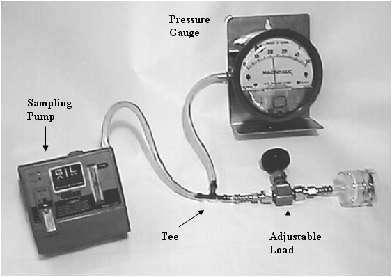
- Adjust the air sampling pump to 1.7 L/min as indicated on the bubble meter,
and adjust the loading, if necessary, to produce a water indication of 2 to 5
inches on the pressure (vacuum) gauge.
- Increase the loading by slowly closing the valve until the pressure (vacuum)
gauge indicates between 25 and 35 inches of water, and check the flow rate
again. The flow rate should remain at 1.7 L/min ±5%.
- Finally, replace the load and bubble meter with the cyclone and a clean
filter installed, and verify that the loading caused by the cyclone assembly is
between 2 and 5 inches of water pressure (see Figure II: 1–7b).
Confirm that the sampling pump is adjusted properly and take additional
calibrator readings. Three or more consecutive readings should be taken and
should be within about 2% of each other and then averaged.
FIGURE II: 1–7b. SETUP OF JARLESS CYCLONE METHOD WITH CYCLONE ASSEMBLY IN–LINE
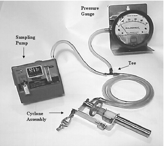
- This calibration method actually performs a dynamic test of the pump under
load.
C. Electronic Flow Calibrators
The Gilian Gilibrator® shown in Figure II: 1-8 is an electronic bubble flow
meter, used to calibrate sampling pumps, that provides instantaneous air-flow
readings and cumulative averaging of multiple measurements. These calibrators
measure the flow rate and display the results as volume per unit of time (e.g.,
mL/min) and can be used to calibrate most air sampling pumps. The range with
different cells is from 1 mL/min to 30 L/min. Gilibrators should not be left
plugged into the charger for extended time periods because the service life of
the battery will be decreased.
FIGURE II:1-8. GILIAN GILIBRATOR PUMP
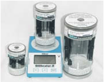
The Bios DryCalTM DC-Lite® shown in Figure II:1-9 is an electronic dry-piston
flow meter used to calibrate sampling pumps that provides immediate and average
readings. The device can be used to calibrate either pressure (labeled inlet) or
vacuum (labeled outlet) flow sources. The vacuum port is used to calibrate
sampling pumps, and the pressure port is used to calibrate the outlet of
sampling pumps used to fill gas sampling bags. The DC-Lite has a lead-acid
battery and can be left on charge for an indefinite time without damaging the
battery. Different models of the instrument cover an optimum flow range of 1 mL/min
to 30 L/min. Do not use the DC-Lite with MSA Escort® ELF pumps because operation
of the pump is affected by the DC-Lite.
FIGURE II: 1–9. BIOS DRYCAL TM DC-LITE PUMP CALIBRATOR
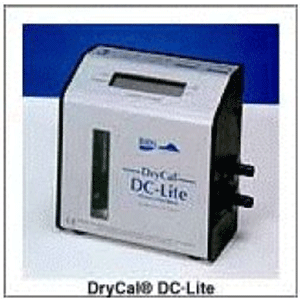
The Cincinnati Technical Center (CTC) recommends that the DC-Lite not be used in
a very dusty environment because dust that flows through the calibrator piston
area has the potential to scratch the glass and piston inside the calibrator.
The CTC also recommends that neither the Gilibrator nor the DC-Lite flow
calibrator be used in corrosive or otherwise contaminated environments.
Properly functioning and calibrated Gilibrators and DC-Lites have an accuracy of
approximately 99%. The appropriate Gilibrator cell or model DC-Lite must be used
for the flow to be measured. It is recommended that the flow rates obtained from
these devices be reported to three significant figures. For example, a flow rate
shown as 1.006 L/min should be reported as 1.01 L/min.
D. Procedures
NOTE: The following instructions and figures were written for the Gilian
Gilibrator flow calibrator, however, the DC-Lite flow calibrator can be
substituted in most cases except for use with MSA Escort ELF pumps.
- Perform the calibration at the pressure and temperature where the sampling is
to be conducted. If this is not possible, consult the operating manual for the
sampling pump to determine if the air volume needs to be adjusted for
temperature and pressure. Allow the pump to run for five minutes before voltage
check and calibration.
- Assemble the cassette filter holder using the appropriate filter (or other
sampler) for the sampling method. Compress the cassette using a mechanical press
or other means of applying pressure. Do not mix brands of cassette components.
Examine the assembled cassette to make certain that the joints fit together
securely to ensure that the cassette does not leak. Use shrink tape around the
cassette to cover joints, but do not rely on the tape to prevent leaks. If a
cassette adapter is used to connect the cassette to the sampling pump, care
should be taken to ensure that it does not come in contact with the back-up pad.
Cassette adapters can cause moderate to severe pressure drop at high flow rates
and can affect the calibration result. If adapters are used for sampling, they
should also be used when calibrating. CAUTION: Nylon adapters can restrict air
flow due to plugging. Stainless-steel adapters are preferred. Do not use
adapters with asbestos filter cassettes.
- Connect the collection device, tubing, pump, and calibration apparatus as
shown in Figure II: 1-10 for the cassette sampler and Figure II: 1-11 for the
Dorr-Oliver cyclone sampler.
- Visually inspect all plastic tubing connections. Be certain that there are no
leaks.
- Gilibrator: Wet the inside of the electronic flow cell with the soap solution
by pushing on the button several times.
DC-Lite: No preparation required.
- Turn on the pump and adjust the rotameter (if so equipped) to the appropriate
flow rate.
- Gilibrator: Press the button on the electronic bubble meter. Visually capture
a single bubble and electronically time the bubble. The accompanying printer
will automatically record the calibration reading in liters per minute.
DC-Lite: Press and release the Read button for a single measurement. Press and
hold the Read button for consecutive measurements.
- Adjust the sampling pump to the correct flow rate using the calibrator
results. Adjust the sampling pump while it is running.
- Confirm that the sampling pump is adjusted properly and take additional
calibrator readings. Three or more consecutive readings should be taken and
should be within about 2% of each other and then averaged.
- Repeat the procedures described above for all pumps to be used for sampling.
The same cassette and filter may be used for calibrations involving the same
sampling method. Do not use the actual cassette and filter intended for sampling
use to perform calibration.
FIGURE II: 1-10. CASSETTE IS ATTACHED TO ELECTRONIC BUBBLE METER FOR CALIBRATION
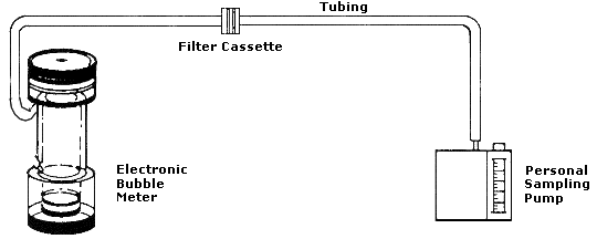
E. Calibration Procedures for Cyclones or for Open–Face Filters
- Perform the calibration at the pressure and temperature where sampling is to
be conducted. If this is not possible, consult the operating manual for the
sampling pump to determine if the air volume needs to be adjusted for
temperature and pressure.
- Set up the calibration apparatus as shown in Figure II: 1-11. Be certain
there are no leaks. A cyclone leak test kit is available from CTC.
- Place the open-face filter cassette or cyclone assembly in a 1-liter jar. The
jar is provided with a special cover. Open-face cassettes are used for asbestos
and other chemicals such as isocyanates, crotonaldehyde and glutaraldehyde.
- Connect the tubing from the electronic bubble meter to the inlet of the jar.
- Connect the tubing from the outlet of the cyclone holder assembly or from the
filter cassette to the outlet of the jar and then to the sampling pump.
- Calibrate the pump with a light load (typically a 5-µm, 37-mm filter) and a
heavy load (created by slightly pinching the tubing), both pre- and
post-sampling. All readings must be within five percent of each other. Detailed
instructions on leak testing are available from the CTC and can also be found in
Technical Links on OSHA's web page for
silica. See also APPENDIX II: 1-5 CYCLONE
ASSEMBLY AND CLEANING INSTRUCTIONS, of this document.
FIGURE II: 1-11. CALIBRATE BY PLACING THE CYCLONE IN A 1-LITER VESSEL ATTACHED
TO AN ELECTRONIC BUBBLE METER
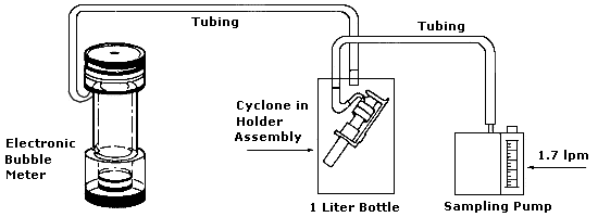
F. Calibration of Impingers and Bubblers
- Set up the calibration apparatus as shown in Figure II: 1-10 and replace the
cassette with an impinger or bubbler filled with the amount of liquid reagent
specified in the sampling method. (Refer to Chemical Sampling Information file.)
- Connect the tubing from the electronic bubble meter to the inlet of the impinger or bubbler.
- Connect the outlet of the impinger or bubbler to the tubing to the pump. Be
certain there are no leaks.
- Calibrate the pump to the flow rate specified in the Chemical Sampling
Information file for the sampling method.
G. Maintenance and Care of Electronic Calibrators
Consult the manufacturer's instruction manuals for complete details.
Periodically, compare the calibrator to another unit to make sure that it is
functioning properly. Return the calibrator to CTC annually to be calibrated and
serviced.
Gilian Gilibrator:
- Clean the unit before use following storage. Remove the flow cell and gently
flush it in accordance with the manufacturer’s recommendations. The acrylic flow
cell can be easily scratched. Wipe with cloth only. Do not allow the center
tube, where sensors detect the soap bubble, to be scratched or to get dirty.
Never clean the cell with acetone, alcohol or other cleaning solutions. Use only
soap and warm water. When cleaning prior to storage, allow the flow cell to air
dry. If stubborn residue persists, it is possible to remove the bottom plate.
Squirt a few drops of soap into the slot between the base and flow cell to ease
removal.
- Leak testing. A leak test is described in the Gilibrator manual. The system
should be leak checked at 6 inches of water pressure by connecting a manometer
to the outlet and evacuating the inlet to 6 inches of water pressure. No leakage
should be observed. Never pressurize the flow cell with more than 25 inches of
water pressure. CTC will perform a leak check as part of their annual service.
- Verification of Calibration. The calibrator is factory calibrated using a
standard traceable to the National Institute of Standards and Technology. Tests
to verify calibrator calibration against a glass 1-L buret should be conducted
at 1000 mL/min for maximum accuracy. The calibrator is linear throughout the
entire range. CTC will calibrate the unit as part of their annual service.
- When transporting the calibrator, especially by air, it is important that one
side of the seal tube which connects the inlet and outlet be removed to equalize
internal pressure within the calibrator. Do not transport the unit with soap
solution or with storage tubing in place.
- The calibrator soap is a concentrated and sterile solution formulated to
provide a clean, frictionless soap film bubble over the wide, dynamic range of
the calibrator. The sterile nature of the soap is important in order to prevent
residue build-up in the flow cell center tube, which could cause inaccurate
readings. The use of any other soap is not recommended. Proper soap solution is
available from CTC's expendable supplies program.
- Do not charge batteries for more than 16 hours. Do not constantly charge the
calibrator when not in use because this could damage the battery.
- Do not store the calibrator for more than a week with soap solution in the
cell. Clean the unit and store dry.
Bios DryCal DC-Lite:
- Do not use liquid solvents or abrasive cleaners to clean the calibrator; wipe
only with a cloth lightly dampened with water. Store the instrument in a clean,
dry place and with the unit on charge, if possible.
- Leak testing. Place the manufacturer supplied leak-test accessory (short
piece of latex with a red plug) over the inlet (top port). Press and hold the
Stop button and then press the ON button. The display should read "Leak Test,
Invert & Push Read." Invert the unit and push Read. Turn the unit upright and
allow it to stand. Make sure that the piston is at the top of the cell. Allow
the calibrator to stand until the piston falls; this may take as long as 15-20
min. The unit will display "Test OK Press Read" if it passes the test. Repeat
the leak test with the leak-test accessory over the outlet (bottom port).
- Calibration. Bios recommends that the unit be recalibrated by the
manufacturer annually. CTC will calibrate the unit as part of their annual
service.
H. Manual Buret Bubble Meter Technique
When a sampling train requires an unusual combination of sampling media (e.g.,
glass-fiber filter preceding impinger), the same type media/devices should be
in-line during calibration. Do not use the actual filter cassette intended for
sampling. Calibrate personal sampling pumps before and after each day of
sampling.
- Allow the pump to run 5 minutes prior to voltage check and calibration.
- Assemble the cassette filter holder using the appropriate filter for the
sampling method. If a cassette adapter is used, care should be taken to ensure
that it does not come in contact with the back-up pad.
NOTE: When calibrating with a bubble meter, the use of cassette adapters can
cause a moderate to severe pressure drop in the sampling train, which will
affect the calibration result. If adapters are used for sampling, then they
should be used when calibrating.
- Connect the collection device, tubing, pump, and calibration apparatus as
shown in Figure II: 1-12 or in Figure II: 1-13. Be certain that there are no
leaks.
FIGURE II: 1-12. CALIBRATION FOR PERSONAL SAMPLING WITH FILTER CASSETTE USING AN
INVERTED BURET
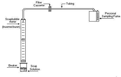
FIGURE II: 1-13. CALIBRATION OF CYCLONE SAMPLER USING AN INVERTED BURET
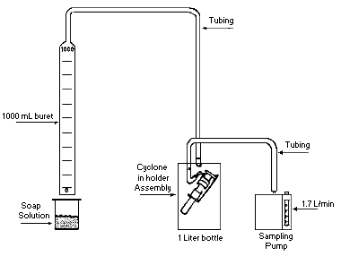
- A visual inspection should be made of all plastic tubing connections. Be
certain there are no leaks.
- Wet the inside of a 1000-mL buret with a soap solution.
- Turn on the pump and adjust the pump rotameter (if present) to the
appropriate flow rate setting.
- Momentarily submerge the opening of the buret in order to capture a film of
soap.
- Draw two or three bubbles up the buret in order to ensure that at least one
bubble will complete its run.
- Visually capture a single bubble and time the bubble from 0 to 1000 mL for
high flow pumps or 0 to 100 mL for low flow pumps.
- The accuracy of the timing device should be 99%. If the flow rate is not
within the desired range, adjust the flow rate and repeat step 9 until the
correct flow rate is achieved. Perform step 9 at least three times.
- Repeat the procedures described above for all pumps to be used for sampling.
The same cassette and filter may be used for all calibrations involving the same
sampling method.
I. Precision Rotometer Method
Although OSHA allows the use of precision rotameters for sampling pump
calibration, this device is no longer recommended and should not be used unless
absolutely necessary. Tests have shown significant measurement error due to pump
pulsation. These pulsations are typically not observable by the user. The
precision rotameter (Figure II: 1-14) is a secondary calibration device. If it
is to be used in place of a primary device such as a bubble meter, take care to
ensure that any error introduced by its use will be minimal and noted.
FIGURE II: 1–14. SINGLE COLUMN PRECISION ROTOMETER
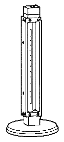
NOTE: The precision rotameter can be used for calibrating the personal sampling
pump in lieu of a bubble meter, only if it is:
- Calibrated regularly, at least monthly, with an electronic flow calibrator or
with a manual buret bubble meter and an appropriate vacuum source. Calibration
points should include duplicate readings at each major division of the rotameter
(e.g., 1, 2, 3, etc.). Calibration must bracket the flow rate to be measured
with the precision rotameter and will usually contain ten duplicate calibration
points including the flow rate of interest. Record the temperature and
barometric pressure at which the calibration was performed.
- Disassembled, cleaned as necessary, and recalibrated.
- Used with care to avoid dirt and dust contamination, which may affect the
flow.
- Not used at substantially different temperature and/or barometric pressure
from conditions present when the rotameter was calibrated against the primary
source. If altitude or temperature at the sampling site is substantially
different from the calibration site, it is necessary to calibrate the precision
rotameter at the sampling site.
- Used in such a way that the pressure drop across it is minimized.
APPENDIX II: 1-2.
A. Pre–Weighed Filters
The SLTC provides pre-weighed filters for gravimetric analysis. Filter/cassette
units, when assembled in a cassette by the manufacturer, are tested for leaks.
These filter/cassette units reduce sample preparation time by CSHOs because the
filters are weighed at the SLTC and the units are shipped to the field fully
assembled and ready for use. The filter/cassette units are returned to the SLTC
for gravimetric determinations and additional analyses as needed. The filter
medium is 5-μm, 37-mm diameter, low-ash polyvinyl chloride (PVC) or
polytetrafluoroethylene (PTFE or TEFLON®). The PVC filters should be used for
silica (quartz) analysis, aluminum, and other appropriate substances having high
PELs or requiring gravimetric analysis. The PTFE filters are used for asphalt
fumes. The filters may be used with or without a cyclone. Other than for silica,
if the gravimetric analysis yields a result less than the PEL for the requested
substance(s), no further analysis will be provided unless specifically
requested. The filter/cassette unit is shown in Figure II:1-15 and should be
used only for samples requiring crystalline silica gravimetric analysis or other
gravimetric analysis. Appendix II:1-4 is a partial listing of substances that
should be sampled and analyzed gravimetrically using pre-weighed cassettes.
FIGURE II: 1-15. FILTER/CASSETTE UNIT
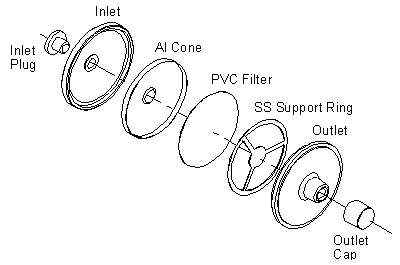
Due to the slightly smaller size of the filter, check it frequently to avoid
overloading. This can be accomplished by looking into the inlet sampling port of
the cassette. Use a flashlight, if necessary. Visual observation of the airborne
dust in the workplace may assist in determining how frequently to check the
filter for overloading. If used with a cassette, do not lift the cyclone in such
a way that particles from the grit pot could be deposited on the filter.
As shown in Figure II:1-15, the inlet side of the cassette is marked on the
polystyrene cassette. This is the side of the filter cassette with the aluminum
cone antistatic shield. The stainless steel support (Figure II:1-16) is visible
from the outlet side of the assembly. Each of the filter assemblies is bar coded
for weighing purposes (Figure II: 1-17). To aid in tracking the filters, please
use the barcode number as the sample submission number when filling out Form
OSHA- 91A (Air Sampling Worksheet). A blank should be included with every set of
samples.
FIGURE II: 1-17
TOP AND BOTTOM

|
FIGURE II: 1-16
STAINLESS STEEL FILTER SUPPORT
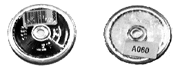
|
|
Inlet |
Outlet |
The filter/cassette assembly can be used with both nylon cyclone and holder
assemblies currently in field use; however, the standard MSA coupler (used with
a standard 2- or 3- piece cassette) will not fit these cassettes. Another coupler
available from MSA (part #457391), which is plastic instead of stainless steel,
can be obtained from the CTC.
APPENDIX II: 1-3.
A. Shelf Life of Sampling Media Provided by the SLTC
Table 3
SHELF LIFE OF SAMPLING MEDIA PROVIDED BY THE SLTC
|
Sampling medium
|
Shelf life
|
Comments
|
Sodium hydroxide (all normalities)
|
6 months
|
|
Hydrochloric acid
Sulfuric acid
Methanol in water
|
1 year
|
Same for all concentrations
|
Solution for bis-chloromethyl ether
(BCME) and chloromethyl methyl
ether (CMME)
|
2 months
|
Prepared on request*
|
Hydroxylammonium chloride solutions
(for ketene collection)
|
2 weeks
|
Prepared on request*
|
Hydroxylammonium chloride-sodium hydroxide mixed solutions (for ketene
collection)
|
Stable only
2 hours
|
CSHO must prepare solution from two component solutions just before use*
|
Folin's reagent
|
5 days
|
Prepared on request*
|
Diffusive samplers
|
|
Must be used before the expiration date (if given) printed on the monitor
package
|
Nitrogen oxides collection tubes
|
2 years
|
Should be stored in a refrigerator
|
Sampler for ozone
(Nitrite-treated filter collection device)
|
28 days
|
Prepared on request*
|
Coated filter sampler for diisocyanates
(MDI, HDI, TDI, etc.)
|
1 year
|
Prepared on request*
|
NaOH coated binderless quartz fiber
filters
|
3 months
|
Prepared on request*
|
Treated filter sampler for collection of anhydrides
|
30 days
|
Prepared on request*
|
|
* Give the SLTC at least two days notice to allow time for reagent preparation.
APPENDIX II: 1-4.
Table 4
PARTIAL LIST OF SUBSTANCES FOR GRAVIMETRIC DETERMINATION
|
Substance
|
IMIS
|
PEL (mg/m3)
|
Substance
|
IMIS
|
PEL (mg/m3)
|
alpha-Alumina..........
Total dust........... |
|
|
Oil mist (mineral) |
5010 |
5 |
|
0160 |
15 |
|
Respirable fraction.. |
A201 |
5 |
Particulates not
otherwise regulated
(PNOR)............ |
|
|
|
Aluminum metal (as Al). |
|
|
Total dust........... |
9135 |
15 |
|
Total dust........... |
A100 |
15 |
Respirable fraction.. |
9130 |
5 |
|
Respirable fraction.. |
A110 |
5 |
Pentaerythritol........
Total dust........... |
|
|
|
1987 |
15 |
Ammonium sulfamate.....
Total dust........... |
|
|
Respirable fraction.. |
P157 |
5 |
|
0185 |
15 |
|
Respirable fraction.. |
A111 |
5 |
Perlite................
Total dust........... |
|
|
|
2035 |
15 |
Barium sulfate.........
Total dust........... |
|
|
Respirable fraction.. |
P101 |
5 |
|
B101 |
15 |
|
Respirable fraction.. |
B104 |
5 |
Plaster of paris.......
Total dust........... |
|
|
|
2127 |
15 |
Bismuth telluride
Undoped..............
Total dust........... |
|
|
Respirable fraction.. |
P102 |
5 |
|
0370 |
15 |
|
Respirable fraction.. |
B110 |
5 |
Portland cement........
Total dust........... |
|
|
|
0557 |
15 |
Boron oxide............
Total dust........... |
0380 |
15 |
Respirable fraction.. |
P104 |
5 |
Calcium carbonate......
Total dust........... |
|
|
Rouge..................
Total dust........... |
|
|
|
0505 |
15 |
2229 |
15 |
|
Respirable fraction.. |
C130 |
5 |
Respirable fraction.. |
R102 |
5 |
Calcium hydroxide......
Total dust........... |
|
|
Silica, amorphous,
precipitated and gel. |
9050 |
|
|
15 |
Respirable fraction..
|
|
5
|
|
|
|
|
|
Substance
|
IMIS
|
PEL (mg/m3)
|
Substance
|
IMIS
|
PEL (mg/m3)
|
|
Calcium oxide.......... |
0520 |
5 |
diatomaceous earth,
containing less than
1% crystalline silica |
S112 |
|
|
Calcium silicate....... |
|
|
Silica, crystalline
cristobalite, |
|
|
|
Total dust........... |
C112 |
15 |
respirable dust...... |
9015 |
|
|
Respirable fraction.. |
C122 |
5 |
Silica, crystalline quartz, |
|
|
|
Calcium sulfate........ |
|
|
respirable dust......... |
9010 |
|
|
Total dust........... |
C104 |
15 |
Silica, crystalline
tripoli (as quartz), |
|
|
|
Respirable fraction.. |
C123 |
5 |
respirable dust...... |
S114 |
|
|
Carbon black........... |
0527 |
3.5 |
Silica, crystalline tridymite, |
|
|
|
Cellulose.............. |
|
|
respirable dust...... |
9017 |
|
|
Total dust........... |
0575 |
15 |
Silica, fused, |
|
|
|
Respirable fraction.. |
C124 |
5 |
respirable dust...... |
9013 |
|
Coal dust (less than
5% SiO(2)),
respirable fraction.. |
9040 |
|
Silicates (less than 1%
crystalline silica) |
|
|
Coal dust (greater than
or equal to 5% SiO(2)),
respirable fraction............. |
C120 |
|
Mica (respirable dust)........
|
|
|
|
|
|
|
Soapstone, total dust |
9025 |
|
|
|
|
|
Soapstone, respirable
dust................. |
S121 |
|
|
Cotton Dust (The SLTC will supply special pre-weighed cotton dust filters and
cassettes on request.) |
Talc (containing no
asbestos), |
|
|
|
Dicyclopentadienyl iron |
|
|
respirable dust...... |
9030 |
|
|
Total dust........... |
0904 |
15 |
Silicon................ |
|
|
|
Respirable fraction.. |
D100 |
5 |
Total dust........... |
2235 |
15 |
|
Emery.................. |
|
|
Respirable fraction.. |
S120 |
5 |
|
Total dust........... |
1016 |
15 |
Silicon carbide........ |
|
|
|
Respirable fraction.. |
E102 |
5 |
Total dust........... |
2236 |
15 |
|
Grain dust (oat, wheat, barley)........ |
G109 |
10 |
Respirable fraction.. |
S123 |
5 |
Glycerin (mist)........
Total dust........... |
|
|
Starch................. |
|
|
|
1363 |
15 |
|
Respirable fraction.. |
G115 |
5 |
Total dust........... |
2263 |
15 |
|
Graphite, synthetic.... |
|
|
Respirable fraction.. |
S124 |
5 |
|
Total dust........... |
1366 |
15 |
Sucrose................ |
|
|
|
Respirable Fraction.. |
G100 |
5 |
Total dust........... |
2285 |
15 |
|
Gypsum................. |
|
|
Respirable fraction.. |
S130 |
5 |
|
Total dust........... |
1367 |
15 |
Tantalum, metal and |
|
|
|
Respirable fraction.. |
G101 |
5 |
oxide dust........... |
2325 |
5 |
|
Kaolin................. |
|
|
Titanium dioxide...... |
|
|
|
Total dust........... |
1568 |
15 |
Total dust........... |
2440 |
15 |
|
Respirable fraction.. |
K100 |
5 |
|
|
|
|
|
Substance
|
IMIS
|
PEL (mg/m3)
|
Substance
|
IMIS
|
PEL (mg/m3)
|
|
|
|
|
Vegetable oil mist..... |
|
|
|
Total dust........... |
1593 |
15 |
Total dust........... |
V126 |
15 |
|
Respirable fraction.. |
L100 |
5 |
Respirable fraction.. |
V127 |
5 |
|
Magnesite.............. |
|
|
Zinc oxide fume........ |
2610 |
5 |
|
Total dust........... |
M113 |
15 |
Zinc oxide............. |
|
|
|
Respirable fraction.. |
1615 |
5 |
Total dust........... |
Z102 |
15 |
|
Magnesium oxide fume... |
|
|
Respirable fraction.. |
Z103 |
5 |
|
Total particulate.... |
1610 |
15 |
Zinc stearate.......... |
|
|
|
Marble................ |
|
|
Total dust........... |
2616 |
15 |
|
Total dust........... |
1626 |
15 |
Respirable fraction.. |
Z104 |
5 |
|
Respirable fraction.. |
M114 |
5 |
Zirconium compounds
(as Zr).............. |
2620 |
5 |
|
APPENDIX II: 1-5.
CYCLONE ASSEMBLY AND CLEANING INSTRUCTIONS
A. Cyclone Assembly
1. Inspect the cyclone parts for signs of wear or damage such as scoring,
rifling, or a loose coupler. Replace the units or parts if they appear damaged.
2. Leak test the cyclone before use unless it has been leak tested within the
past month. A Cyclone Leak Test Kit and Cyclone Leak Test Procedure are provided
in each Area Office for this purpose. Detailed instructions on leak testing are
available from the CTC and through Technical Links on OSHA's web page for
silica.
FIGURE II: 1-18. CYCLONE ASSEMBLY
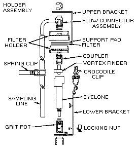
Unscrew the grit pot from the cyclone. Empty the grit pot by turning it upside
down and tapping it gently on a solid surface. Clean the cyclone thoroughly and
gently after each use in warm soapy water or, preferably, wash it in an
ultrasonic bath. Rinse it thoroughly in clean water, shake off excess water, and
set aside to dry before reassembly. Never insert anything into the cyclone
during cleaning (see Figure II: 1-18).
APPENDIX II: 1-6.
CHAIN OF CUSTODY
SLTC uses OSHA's established chain-of-custody procedures to track whether
official Form OSHA-21 seals were properly used to ensure the integrity of
samples collected by OSHA CSHOs. The procedure also tracks the history and
control of samples received at the SLTC. The chain of custody includes the dates
the sample was collected, shipped to the SLTC, received at the SLTC, the analyst
received the sample, the analysis was completed, the analytical results were
checked by another analyst, and the sample results were released by a supervisor
or his/her representative. It is important to follow chain-of-custody
requirements because it legally documents handling of OSHA samples for
litigation purposes.
APPENDIX II: 1-7.
HOW TO APPLY FORM OSHA-21 TO CHARCOAL TUBES AND FILTER CASSETTES
FIGURE II: 1-19. CORRECTLY SEALED CHARCOAL TUBE. CHARCOAL
TUBE INSIDE FORM OSHA-21
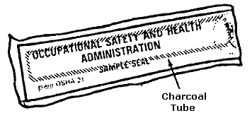
FIGURE II: 1-20. INCORRECTLY SEALED CHARCOAL TUBE. END CAPS CAN BE REMOVED,
ALLOWING SAMPLE INTEGRITY TO BE JEOPARDIZED WITHOUT DISTURBING THE SEAL
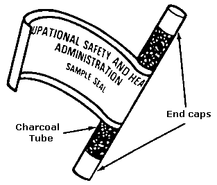
FIGURE II:1-21 INCORRECTLY SEALED
CASSETTE ALLOWS ACCESS TO INLET/OUTLET
PORTS
AFTER SAMPLE HAS BEEN TAKEN
|
FIGURE II:1-22 CORRECTLY SEALED
CASSETTE WITH FORM OSHA-21 COVERING INLET/OUTLET
PORTS MAINTAINING SAMPLE INTEGRITY
|
Figure II: 1-23. STANDARD ASBESTOS CASSETTE (25mm) CORRECTLY SEALED WITH A FORM OSHA–21
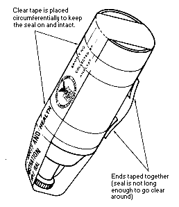
APPENDIX II: 1-8.
FIGURE II: 1-24. FRONT OF COMPLETED AIR SAMPLING WORKSHEET FORM OSHA-91A
FIGURE II: 1-25. BACK OF AIR SAMPLING WORKSHEET FORM OSHA-91A
APPENDIX II: 1-9.
FIGURE II: 1-26. COMPLETED SOIL SAMPLING WORKSHEET ON A FORM OSHA-91A
|

