| 2900 |  |
Figure 8. Valve bottle assembled about 1860, inventor unknown. Left: valve bottle descending. Right: Valve bottle ascending after obtaining sample. This bottle was constructed by Max Marx. |
|
2901 | 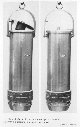 |
Figure 9. Old hinged valve bottle; inventor unknown; date of first use unknown. This example was constructed by Max Marx. Left: Appearance on descent. Right : after closing and ascending. |
|
2902 |  |
Figure 10. Piston bottle for acquiring water from near the bottom. The inventor is unknown. However, such a bottle was constructed for the Commission of Kiel in 1870. This instrument was made by Max Marx in about 1913. Left: descending. Right: ascending. |
|
2903 |  |
Figure 11. Meyer glass water sampling bottle invented by Dr. Adolph Meyer of the Commission of Kiel and used on the POMMERANIA for studies in the Baltic Sea in 1871. This sampling bottle was used in surface layers of water to about 10 meters. Left: descending. Right: ascending. |
|
2904 |  |
Figure 12. Behrens and Jacobsen water sampling bottle invented by Doctor Oscar Jacobsen and Heinrich Behrens at the University of Kiel in 1872. Water samples were recovered for study of dissolved gases during the POMMERANIA expedition to the North Sea in 1872. Left: descending. Right: on the bottom, ready for ascent. |
|
2905 | 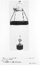 |
Figure 13. Behrens and Jacobsen water bottle (second model, 1873.) The rubber sampling bottle is missing in this example. In descending mode. |
|
2906 | 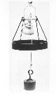 |
Figure 13 (cont). Behrens and Jacobsen water bottle (second model, 1873.) The rubber sampling bottle is missing in this example. On the bottom. |
|
2907 | 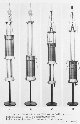 |
Figure 14. Meyer bottle, invented by Heinrich Adolph Meyer, of the Commission of Kiel, and built by Carl Seeman. A and B are deep water set up; A descending , B at the bottom; C shallow-water setup descending, D ascending. These bottles were used during the POMMERANIA expedition in the North Sea in 1872 and in 1874 during the GAZELLE circumnavigation of the Earth. |
|
2908 |  |
Figure 15. Meyer bottle, invented by Heinrich Adolph Meyer, of the Commission of Kiel, and built by Ludwig Steger. A and B are deep water set up; A descending, B at the bottom; C shallow-water setup descending, D ascending. These bottles were used during the POMMERANIA expedition in the North Sea in 1872 and in 1874 during the GAZELLE circumnavigation of the Earth. |
|
2909 | 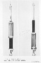 |
Figure 16. Milne bottle constructed by James Milne of Edinburg and used on the CHALLENGER Expedition. Left: descending. Right: ascending. This type of bottle was modified from the design of the Meyer bottle. |
|
2910 |  |
Figure 17. Challenger model of the Buchanan bottle, devised by the chemist of the expedition, John Buchanan, to sample intermediary layer waters. Left: descending. Middle: closing. Right: ascending. This type of bottle was used during the course of the voyage, from 1872 to 1876. |
|
2911 |  |
Figure 18. Sigsbee bottle in open position, invented by Lieutenant Charles D. Sigsbee, USN, in 1875. This bottle was used on the Coast and Geodetic Survey Ship BLAKE. This type of bottle was used by the navies of many nations. The bottle as shown is in the open position. |
|
2912 |  |
Figure 19. Wille bottle, invented by Captain Carl F. Wille, commandant of the Norwegian navy oceanographic ship VORINGEN in 1875 and used for North Atlantic studies. Right: detail of the closing mechanism. |
|
2913 | 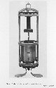 |
Figure 20. Ekman insulated bottle invented by Professor Fredrik Eckman for studies of the temperature and salinity of the waters of the Skagerrak in 1869. A model of this type was used by Nordenskiold on the VEGA in 1878 and was also used by the FRAM in 1893. This image shows the bottle in the descending position. |
|
2914 |  |
Figure 21 . Ekman insulated bottle invented by Professor Fredrik Eckman for studies of the temperature and salinity of the waters of the Skagerrak in 1869. A model of this type was used by Nordenskiold on the VEGA in 1878 and was also used by the FRAM in 1893. This image shows the bottle in the ascending position. |
|
2915 | 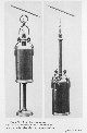 |
Figure 22. Arwidsson bottle invented by the Swede Thorsten Arwidsson in 1879 used by Swedish and Danish investigators. The pencil indicates the placement of of the releasing mechanism. Left: descending. Right: ascending. This type of of bottle was used in 1952 by the Danish light vessel VYL. |
|
2916 |  |
Figure 23. Traivailleur bottle invented by Lieutenants Ernest Richard and Jean de Villegente of the French navy while on the TRAVAILLEUR expedition of 1881. This type of bottle was able to collect water at many depths for analysis of dissolved gases. Left: descending. Right: ascending. |
|
2917 | 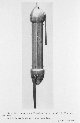 |
Figure 24. Traivailleur bottle invented by Lieutenants Ernest Richard and Jean de Villegente of the French navy while on the TRAVAILLEUR expedition of 1881. This type of bottle was able to collect water at many depths for analysis of dissolved gases. The iron brace is missing in this example. |
|
2918 | 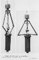 |
Figure 25. Bottom water sampling bottle constructed by Max Marx in 1913. The inventor of this bottle is unknown. Left: descending. Right: ascending. |
|
2919 |  |
Figure 26. A Kidder, Flint and Tanner bottle after the design of the Sigsbee bottle but with several modifications. This bottle was designed by Jerome Kidder of the U. S. Fish Commission, Surgeon James M. Flint of the U. S. Navy, and Commander Zera Luther Tanner, commanding officer of the U. S. Fish Commissio n Steamer ALBATROSS and used in 1885. |
|
2920 |  |
Figure 27. Mill bottle invented by Dr. Hugh R. Mill of the Scottish Marine Station in 1884. This bottle was modified from the design of the Meyer bottle and fitted with a rubber disc to enhance its water-tightness. It also was fitte d with an automatic closing device and became known as the Mill self-locking water bottle. Left: descending. Right: ascending. |
|
2921 |  |
Figure 28. Mill bottle modified with mounting for thermometer devised by Dr. Hugh R. Mill of the Scottish Marine Station at Granton in 1884. Left: descending. Right: ascending. |
|
2922 |  |
Figure 29. An unidentified water sampling bottle. Left: descending. Right: ascending. |
|
2923 | 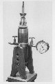 |
Figure 30. High pressure bottle devised by Prince Albert I of Monaco in 1890. The manometer was set in place after the bottle's return from the deep ocean in order to measure the pressure of the water sample. This bottle was used for collecting water samples at depth and returning them to the surface at the ambient water pressure at the depth of the sample. |
|
2924 | 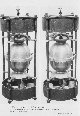 |
Figure 31. Timtschenko water bottle, inspired by the Wille bottle, and built by the instrument maker Iosif A. Timtschenko for sampling waters of the Black Sea and analyzing for dissolved hydrogen sulfide content. This instrument was built in 1891 and used by Joseph B. Spindler in his studies of the Black Sea. The interior was of gold to resist corrosion. Left: descending. Right: ascending. |
|
2925 |  |
Figure 32. Regnard bottle invented by Professor Paul Regnard, deputy director of the Experimental Physiology Laboratory at the Sorbonne, in 1890. Left: descending. Right: ascending. The top balloon is missing in these views. This instrument was used to water depths of about 100 meters. |
|
2926 |  |
Figure 33. The model of Buchanan water bottle used on the PRINCESSE ALICE in 1892. John Buchanan brought a number of these bottles aboard that were used with mixed results. One bottle was destroyed at 1500 meters depth. Left: during descent. Right: during ascent. |
|
2927 | 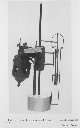 |
Figure 34. Richard mercury bottle shown with the apparatus in the closed position. This apparatus was specially designed by Dr. Jules Richard for use on board the PRINCESSE ALICE in 1896. It sampled water for studying the condition s for the dissolution of gases at various depths. It was used between 1000 and 2700 meters at 3 stations. |
|
2928 | 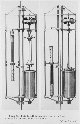 |
Figure 35. Hamberg bottle for sampling intermediate waters devised by Doctor Alex Hamberg at the Institute of Meteorology of the Hogskola at Stockholm in 1898. It was taken on the ANTARCTIC by the Swedish scientist Alfred G. Nathorst and used about Spitzbergen and to the north of Norway. Left: descending. Right: ascending. It sampled both water and temperature. |
|
2929 |  |
Figure 36. Deep water Hamberg bottle devised by Doctor Alex Hamberg at the Institute of Meteorology of the Hogskola at Stockholm in 1898 for use by the Swedish polar expedition on board the ANTARCTIC in 1898. Left: descending. Right: ascending. |
|
2930 |  |
Figure 37. Nansen double bottle invented by Fridtjof Nansen for taking two simultaneous samples. He used these bottles in the Norwegian Sea in 1900 and 1904. Left: descending. Right: ascending. |
|
2931 |  |
Figure 38. Pettersson and Nansen water bottle for obtaining water and temperature observations. This type of bottle had concentric layers of insulating material for keeping the samples at the temperature at which it was obtained. This type of bottle was used by Nansen on the FRAM in 1893 and also used in 1900 on the MICHAEL SARS in the Norwegian Sea. |
|
2932 | 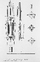 |
Figure 39. Schematic drawing of Pettersson and Nansen bottle as shown by V. W. Ekman in 1905. |
|
2933 |  |
Figure 40. Seligo bottle used to sample a few centimeters below the surface and to avoid floating debris. This was designed in about 1900 by Arthur Seligo. This example was made by Max Marx in 1912. |
|
2934 | 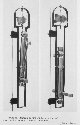 |
Figure 41. Richard bottle, helical model invented by Doctor Jules Richard in 1902. The helical system eliminated the need for a messenger system for inverting the bottle at the desired depth. This type of bottle was used on the PRINCESSE ALICE II in 1902 at a depth of 1870 meters in the Mediterranean Sea. Left: descending. Right: ascending. |
|
2935 | 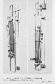 |
Figure 42. Richard bottle, messenger model showing messenger on the line. Designed by Doctor Jules Richard in 1902 and used on the PRINCESSE ALICE II. Left: descending. Right: ascending. |
|
2936 |  |
Figure 43. A modified Richard messenger bottle designed to improve the action of the messenger in inverting the bottle. Commercial manufacture of this type of bottle began in 1911 by Max Marx. |
|
2937 |  |
Figure 44. Water sampling bottles developed by the Central Laboratory at Christiana by Doctor Vagn Ekman, the son of the inventor of the insulation water sampling bottle. The bottle shown is the lateral model. Left: descending. Right: ascending. These bottles were designed in 1902. |
|
2938 | 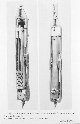 |
Figure 45. Water sampling bottles developed by the Central Laboratory at Christiana by Doctor Vagn Ekman, the son of the inventor of the insulation water sampling bottle. The bottle shown is the "end of cable" model. Left: descending. Right: ascending. These bottles were designed in 1902. |
|
2939 | 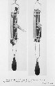 |
Figure 46. Automatic Nansen and Ekman water sampling bottle developed by the Central Laboratory at Christiana by Doctor Vagn Ekman and Fridtjof Nansen. Left: descending. Right: ascending. This type of bottle was used by Nansen in 1910 on board the gunboat FRITHJOF and was used through many hundreds of meters of water depth. |
|
2940 |  |
Figure 47. Schematic drawing of the Nansen and Ekman automatic water sampling bottle as shown by V. W. Ekman in 1905. |
|
2941 |  |
Figure 48. Pettersson universal sampling apparatus devised by the Swedish Professor Otto Pettersson. This instrument would sample plankton, measure the temperature of the water, measure the strength and direction of the current, and sample the water. It was first used in the Skagerrak between 30 and 200 meters depth in January 1904 and afterwards in the Baltic Sea. |
|
2942 | 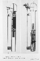 |
Figure 49. Thoulet bottle devised by Professor Julien Thoulet of the Universit y of Nancy. Nothing is known of the use of this bottle. Left: descending. Right: ascending. |
|
2943 | 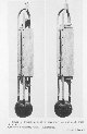 |
Figure 50. Knudsen bottle (first model) for sampling water while a ship is underway. This bottle of very robust construction was devised by the Danish professor Martin Knudsen and used in the Kattegat in 1908 on board the C. F. GROVE and also in 1909 on board the THOR when samples were obtained in 250 meters depth in the North Sea between Aberdeen and Stavanger. |
|
2944 | 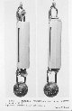 |
Figure 51. Knudsen bottle for sampling water while a ship is underway. A newer revised model built after the model in Figure 50. |
|
2945 | 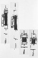 |
Figure 52. Krummel and Ruppin bottle devised by Professor Otto Krummel in 1907 and modified by Ernst Ruppin in 1912. Panel A - 3-liter bottle descending. Panel B. 3-liter model ascending. Panel C. 1-liter bottle descending. Panel D. 1-liter bottle ascending. This type of bottle was used by the POSEIDON about 1912. |
|
2946 |  |
Figure 53. Nansen inverting bottle devised by Fridtjof in1912 and taken by him aboard the ARMAUER HANSEN. Left: descending. Right: ascending. Note the messenger above the bottle in the ascending mode. |
|
2947 |  |
Figure 54. Nansen inverting bottle showing detail of the reversing mechanism. |
|
2948 |  |
Figure 54 (cont). Nansen inverting bottle showing detail of the cable attachment mechanism. |
|
2949 |  |
Figure 55. Richard 1-liter bottle constructed in 1908 for the study of dissolve d gases in bottom water. This bottle was tested on the EIDER, a small vessel belonging to the Oceanographic Museum of Monaco. |
|

