Full Steam Ahead
ATTENTION
This activity should be performed only under teacher/parent supervision.
It requires materials that could be unsafe if used incorrectly.
Author:
Steve Newman, engineer for NASA and co-chair of the Taylor Elementary After-School Hands-on Science Program in Arlington VA
This hands-on activity involves building a steam generator system to power a single-position engine. Because of safety concerns, the generator provides only a very low pressure ("Ahead of steam") and the movement of the piston only approximates that of a piston driven with controlled, regulated, high-pressure steam. Students will learn about the basic components of a steam engine and will understand the need for early train engineers to have dependable fuel and water resources along the railroad right-of-way. Many early railroad outposts served as woodcutting camps and watering or coaling stations, and often were located near river crossings or springs. In many ways, the history of settlement and growth in the western states is linked to servicing the steam-powered "Iron Horse."
The following steam engine construction project involves four stages. First, it requires construction of three principle components: the firebox, the boiler, and the engine. This stage is followed by discussion and analysis and a safety readiness review to prepare students for the final stage: operating the engine.
Materials
The materials for this project can be purchased at your local building supply store for less than $15. You will need
- one unused, gallon-size, metal paint can with lid (if you can find only a used can, make sure it contained latex paint, and clean it thoroughly with soap and water);
- one unused, quart-size, metal paint can with lid (for used cans, apply the same requirements as noted above;
- Six meters soft copper tubing, 1/4 inch in diameter;
- one roll of metallic tape
- two wine corks;
- one circular metallic electrical junction box (used by electricians to connect wires at light fixtures or other junctions);
- one standard electrical cable clamp compatible with the junction box;
- 15 centimeters copper pipe, 2 inch in diameter;
- one 12 x 24-centimeter section of mesh screen, such as the type used for rain-gutter leaf guards;
- 35 centimeters hard plastic tubing, 1/8-1/4 inch in diameter;
- two hose clamps, 1/2-1 1/4 inch;
- charcoal pieces;
- one lightweight wooden skewer (as for barbecuing), about 20 centimeters long;
- a dowel rod 1.5 centimeters long and 3/8 inch in diameter;
- a screwdriver;
- a 1/2-inch-diameter drill (machine bit);
- tin snips;
- pliers;
- hammer; and
- scissors.
STAGE ONE - ASSEMBLY
This engine can be assembled with relative ease if you have access to common shop tolls. You may choose to pre-assemble the engine at home; to have the school maintenance professional assemble it at school; or to have properly equipped and trained students assemble it over a single class period. For the task, you must exercise caution, common sense, and very safety precaution possible, in the case of students= assembling the engine, a safety planning session must be incorporated into the program to identify potential hazards associated with the use of shop tools and the handling of sharp objects. For each potential hazard identified, students should identify a risk-reduction measure. The process of analyzing hazards and identifying risk-reduction measures is an enjoyable, common-sense discipline applicable to this project just as it is when NASA engineers prepare to launch the space shuttle. (The following step-by-step instructions are appropriate for an adult; if students are involved in the construction, you will need to take additional safety measures).
Firebox
To make the firebox, take a permanent marker and draw a 15 x 5-cm rectangle on the outside of the gallon-size can close to the base. With a machine bit, drill a series of holes along the base of the rectangle. Using tin snips, cut through the can between the drilled holes. Then, cut through the can along the two sides of the rectangle. Be careful of the sharp edges. With pliers, pull up and fold against the can's side the flap of metal you've cut out, leaving a 15 x 5-cm opening in the can.
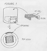
Figure 1
Next, cut a piece of mesh screen into a 12 x 24-centimeter rectangle. On the 24-cm side, bend down approximately 6 cm on each end. Then, insert the mesh platform, resting on the bent edges, into the can, lining the platform up with the opening in the can. (See Figure 1.)
Next, drill holes about one centimeter in diameter through the can's lid along half of the outside perimeter; these holes will provide ventilation for the firebox. The coals will not burn unless they have an adequate supply of oxygen flowing into the firebox flap cut-out and up through these holes.
To make the firebox coil, take soft copper tubing and measure 30 cm from one end. Starting at the 30-cm mark, wind the copper tubing to create five coils, each 12 cm in diameter. Then, wind the remaining tubing to create about 15 coils, each with a diameter of about 8 cm. Make sure that about 20 cm of tubing is left; take that end of the tubing and thread it through one of the end ventilation holes in the lid. Thread the 30 cm of tubing extending from the bottom of the coils through the other end ventilation hole. (See Figure 2.)
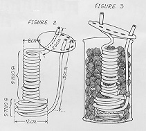
Figures 2 & 3
Next, insert the coil in the paint can, resting it on the mesh platform. Fill the space outside and inside the coil with charcoal pieces. Secure the lid.
Boiler
Construct the boiler from the quart-size paint can. In the center of the can's lid, drill a hole about one centimeter in diameter. Then drill two 1-cm holes through one side of the can, one near the base and the other above it, near the top. (See Figure 4.)
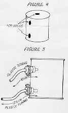
Figures 4 & 5
Using a length of copper tubing that extends from the firebox, bore holes through the centers of the two corks. Be patient, it takes a few minutes. Then, cut two lengths of hard plastic tubing, one piece 25 cm long, the other 10 cm long. Insert the lengths of plastic tubing into the corks so that they fit snugly and protrude slightly at the other ends of the corks. Insert the cork with the longer piece of tubing into the bottom hole and the other cork into the top hole in the side of the boiler can. Secure the hose clamps over the outside ends of the corks. (See Figure 5.)
Next, place the boiler can on top of the firebox can, with the corks facing away from the firebox ventilation holes. Using metallic tape, join and secure the plastic tubing that extends from the bottom cork to the copper tubing that extends from the bottom of the coil. Then join the plastic tubing that extends from the top cork to the copper tubing that extends from the top of the coil, again securing the joint with tape.
Engine
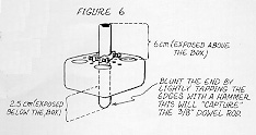
Figure 6
Using a hammer and screwdriver, tap on the center hole of the junction box and remove. Secure the cable clamp to the junction box with the retaining ring on the inside. Next, insert 15 cm of copper pipe through the cable clamp connector. Adjust the length so that the copper pipe will project a few centimeters through the hole in the junction box. Use a hammer to blunt inward the edges of the copper pipe end that projects into the boiler. This will keep the "piston" from falling in the boiler. (See Figure 6.)
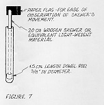
Figure 7
To construct the piston, insert one end of the skewer into the side of the 1.5-cm length of dowel rod (the "piston head"). Place this skewer piston inside the copper pipe. You might also try using a pipe cleaner or plastic drinking straw as the piston. To emphasize the piston's movement, attach a paper flag to the top of the skewer. (See Figure 7.)
STAGE TWO - DISCUSSION & ANALYSIS
Discuss with students the engine's components, their functions, and how they were assembled. Also, track the energy flow that will occur when the engine is operational (the conversion of the chemical energy of the charcoal to the heat energy of the steam to the mechanical energy of the moving piston). Encourage students to think about the way that steam engines rely on two natural resources - coal and water. Discuss the energy-efficiency of modern trains, both diesel-electric and Maglev. Finally, conduct a brainstorming session to identify potential hazards associated with the operation of the model steam engine. Involve students in identifying appropriate risk-reduction measures and form a student team to enforce safety procedures.
STAGE THREE - PREPARING FOR OPERATION
The steam engine should be :
- operated outdoors only (because carbon monoxide is released when charcoal briquettes are burned)
- by the teacher
Because it will take 20-30 minutes to heat the coals and water sufficiently to generate the hot steam needed to move the piston, you may wish to enlist the assistance of parent volunteers or teacher's aides to ignite the coals in advance.
To ensure that the project is fun and safe, carefully observe the following guidelines during this phase of the activity:
- Conduct an "operational readiness check." Review potential hazards and the safety measures to be used. Make sure members of safety team know their assignments.
- Using red cones or a rope, define a "warning ring" on the ground around the steam engine and instruct students not to step inside it (have several adults monitor this). Explain to students that both paint cans, other parts of the engine, and the steam will be very hot. Note: For safety reasons, this engine has been designed to produce very low pressure steam.
- Have available potholders or hot gloves for handling the steam engine.
- Remove any flammable materials from inside the warning ring.
- Place the boiler on a paving stone, ceramic tile, or other non-flammable surface.
- Place a bucket of water next to the steam engine (this will be used to douse the engine after the demonstration is completed.
STAGE FOUR - OPERATION
First, fill the boiler can two-thirds full of water. Check connectors for leaks. Secure the boiler lid by tapping gently with a hammer around the edges of the junction box. (See Figure 8.)
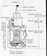
Figure 8
Next, ignite the coals by lighting pieces of crumpled newsprint and then feeding them into the firebox opening (let one piece burn completely before feeding the next). The coals will be ready in less than 30 minutes. (You can accelerate the heating of the coals using a hair dryer or bellows to increase ventilation through the firebox.)
Finally, you will need to adjust the piston. Because the steam buildup is unregulated, the actions of the piston will occur a intervals. As the piston lifts up, steam will leak around it and allow gravity to pull the piston back down. The piston's weight and the available pressure will determine the piston's action. Adjust the piston's weight (by trimming the skewer) as needed to keep it moving smoothly.
Through this hands-on experiment, students will learn how a steam engine operates and observe the conversion of the fossil fuel's potential energy into the piston's mechanical energy. Follow up with a visit to your local train museum so that children can see exactly how the steam-powered piston makes the train's wheels turn.
HAVE FUN !!!