|
|
Glenn
|
This activity was submitted by Richard Glueck, sixth grade teacher at Orono Middle School, Orono, Maine.
Over
a period of 12 years, the Orono Middle School has involved the sixth grade in
an aerospace program that was designed by teachers Richard Glueck and
Christopher Chilelli to go beyond the state educational standards. Since 1991, sixth graders have annually
combined their math and science skills to reproduce faithful, full-size
replicas of the shuttle flight deck, the Mercury and Gemini spacecraft, two
Apollo EVA suits, the M2-F2 lifting body, flying copies of several
Wright
and Chanute gliders, the Ritchel 1896 bicycle powered airship, and a hot air
balloon. Before any of the full-scale
replicas could be undertaken, understanding construction and engineering by
modeling. What follows is a description
of that modeling process, as adapted to building a replica of the
Wright 1902 glider,
in celebration of the Centennial of Flight.
To
set up the program, a blackline drawing of the air or spacecraft being modeled
had to be obtained. The teacher
undertook this job, searching museums, libraries and the web for appropriate
guidelines. One resource that has
proven very useful has been World War I Aero Magazine. For the 1902 glider, I chose to utilize plans
made available on the web at: http://www.first-to-fly.com/Adventure/Workshop/1902plans.htm
These plans are very complete and I edited them a bit to make them 6th
grade friendly.
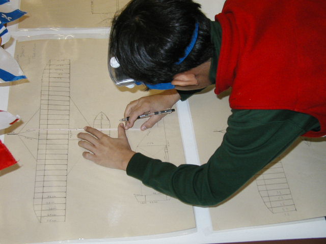
The
first step in the educational plan was to copy three views of the aircraft; one
in profile, one from the top down, and one face-on. We eliminated the measurements on the plans using correction
fluid and challenged the students to use historical photographs of the Wright
1902 glider in flight to estimate a scale.
Certain clues, such as the average height of people in the pictures
allowed students to come up with sensible measurements. We discussed these in class and then applied
the real measurements to the plans. In
fact, this is not far from the efforts facing aviation historians when recreating
the Wright gliders. Measurements are
historical uncertain, and the Brothers used their gliders as fuel for the
woodstove at the conclusion of their experiments!
We
concluded that the glider struts would have measured 60” at the time the
Brothers built their plane. The next
step was to create a scale and teach the kids to figure simple measurement
proportions. If a 60” strut in real
life equaled 4cm on the drawing, the rest of the measurements could be figured
out with little problem. We did this as
classwork, so everyone had the same figures with which to work.
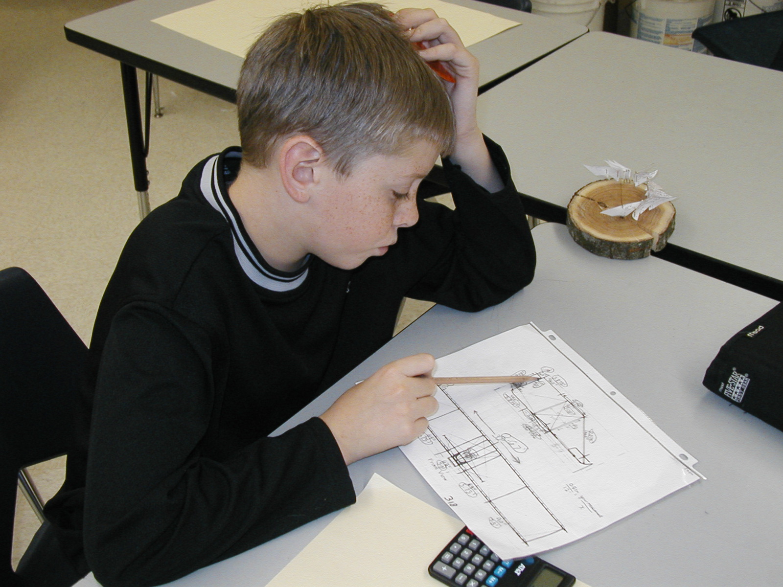
The
next goal of our 6th grade aerospace engineers was to utilize
rulers, protractors, and calculators to draw a larger representation of the
glider in three views. From these student
drawing a model could be built with greater understanding and guidance. Each student drew independently, but all
students could confer and discuss methods of drawing and sharing constructive
criticism. This worked extremely
well. All drawings were then graded
with a rubric that considered proportion neatness, accuracy, and labeling. The premier student drawings were laminated
and posted in the front of the room for reference and to model quality work.
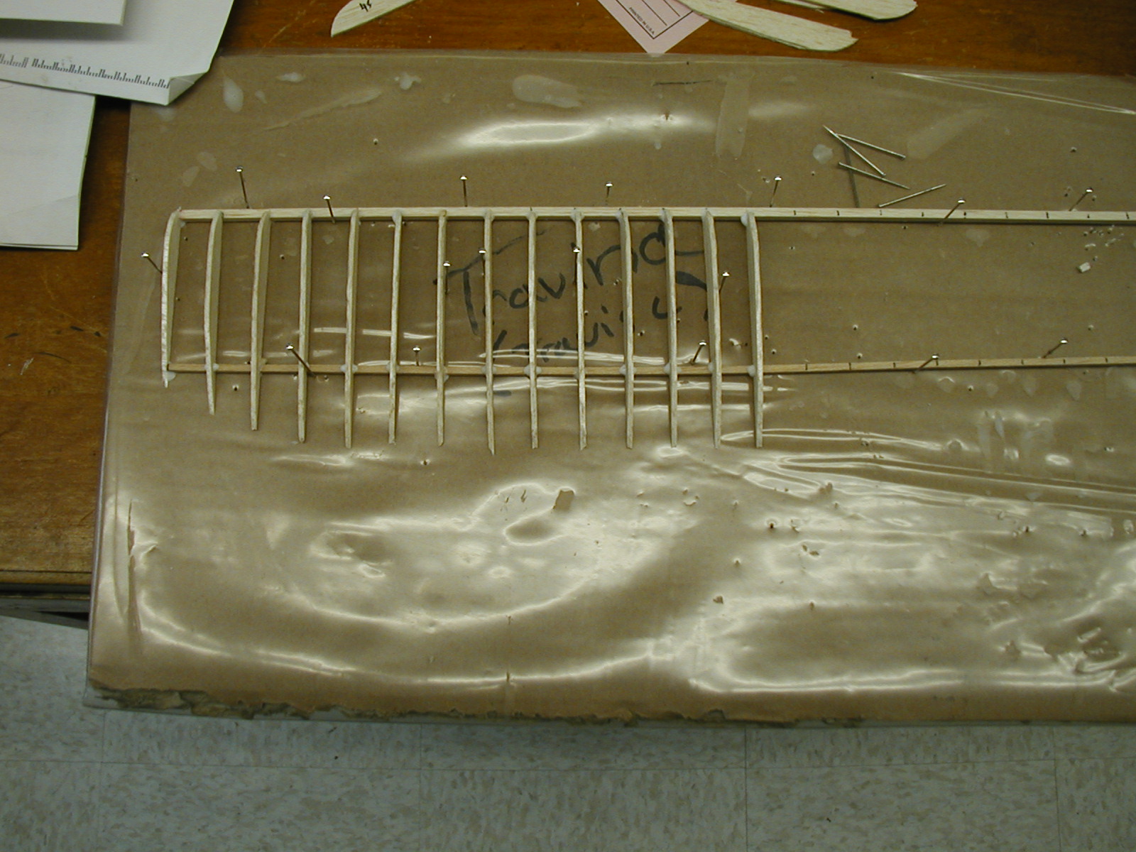
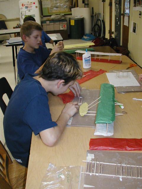
Balsa
wood was ordered from Midwest Products in sheets that measured 3” x 36” x
1/16”. This would be used to for ribs
along the wing skeleton. Spar material
was ordered in two dimensions; 3/32” x 3/32” x 36”, and 1/8” x 1/8” x 36”. The thicker spar material would form the
leading spar while the thinner material would form the trailing spar.
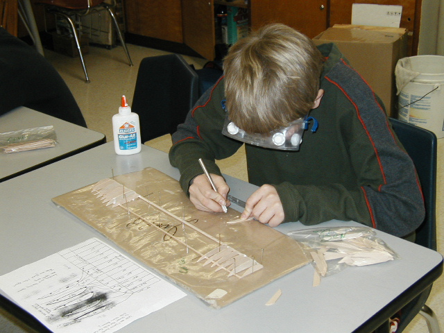
As
teachers we used the drawings made by the students to sketch out five wing rib
templates, each appropriately notched to accommodate the transverse wing
spars. These template shapes were
transferred to the balsa wood for cutting out with X-Acto knives. Certain templates were glued to thicker
cardboard to aid in the scribing. At
one time the High School shop made “cookie cutter” shape in an attempt to
“punch out” ribs, premeasured and quickly.
This did not work well, and the best results came from individual being
responsible for the quality of their own products.
The
assembly process took about two weeks, but rarely have we seen sixth graders so
determined to do a good job on a project.
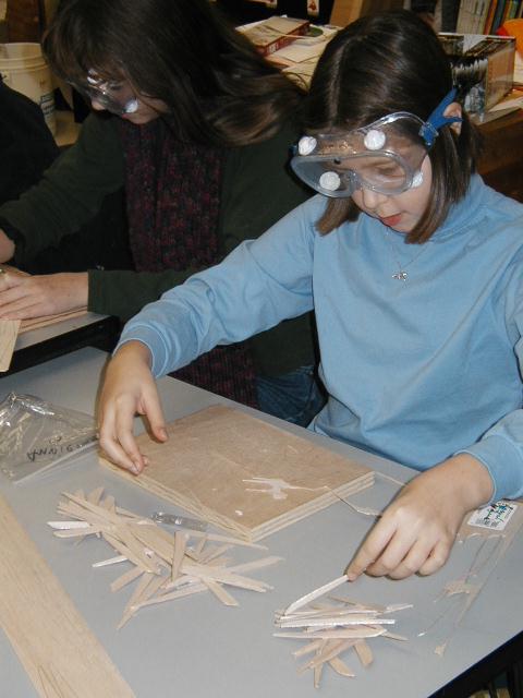
Note that all cutting required students to wear goggles and cutting
boards to protect the desk surfaces.
The adhesive of choice was white glue.
During this time we reinforced proper aircraft terminology as well as
discussing forces of flight in mini-lessons.
Some problems we faced on a daily basis included accounting for your own
wing materials, storage of drying wings, and placing ribs in the correct
locations. The 1/8th square
spar was used as leading spars and the 3/32 square material was used for
trailing spars. The photographs we have
provided illustrate the construction better than words can say.
Please visit the
complete gallery
of photos of the model construction and flight
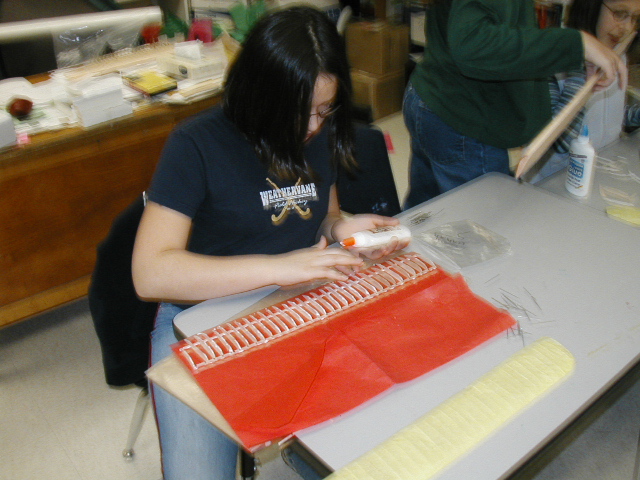
After
wing skeletons were assembled and dried, colored tissue paper was laid out to
wrap each wing. We tried to use tissue
that had a smooth and less porous surface as it resisted tearing a little
better. Wings were wrapped by smearing
white glue along the undersides of the spars and along the tops of the
ribs. When wrapping the wings, we planned
to lay the rear underside of each wing along the tissue paper edge. We folded the tissue up and over the front
of the ribs and then back toward the trailing edge, keeping it as tight and
smooth as possible. This takes a little
practice. When the glue dried, the
paper shrunk a little creating a very effective curvature or dihedral in the
wings. We tucked in loose edges and
trimmed what couldn’t be glued down.
The trailing edge of the wing was formed and firmed into place by
putting white glue on the student’s thumb and forefinger and pulling the paper
to a fine edge.
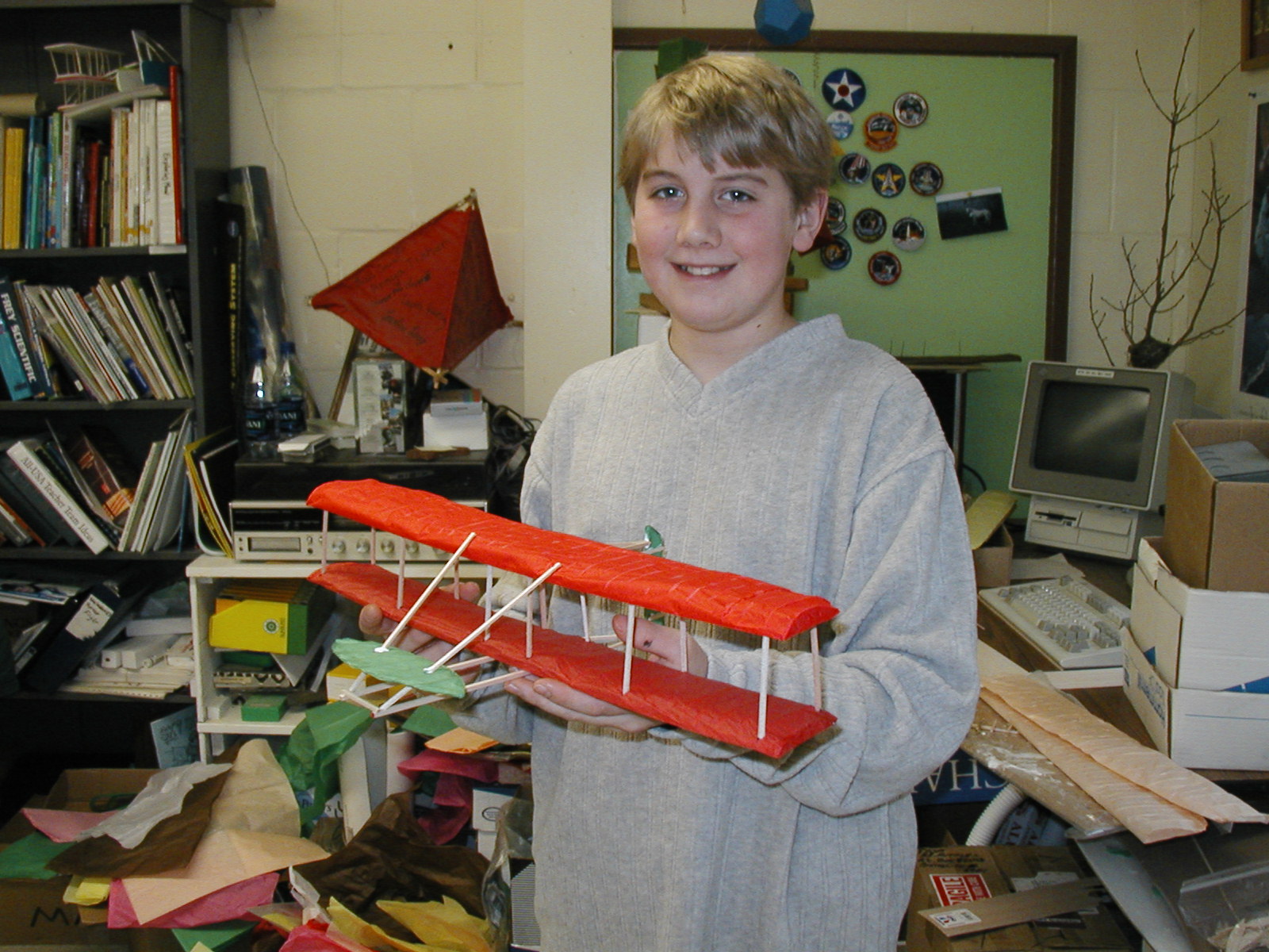
When
both wings were wrapped and trimmed, struts were cut from the left over
3/32-spar material. Using their plans
as guides, they strut openings were marked and cut in the lower wing first. The big concern in gluing struts was to make
sure they were glued exactly perpendicular to the base of the wing and didn’t
lean forward, backward, or to either side.
When the struts were dried over night, the bottom wing was inverted and
the strut holes marked and cut in the top wing. Glue was put on the struts and they were inserted into the
underside of the top wing, and allowed to dry.

The
elevator and rudder were built out of the leftover spar materials, wrapped and
glued between two layers of tissue paper.
Underside skids, braces, and rudder assemblies were constructed from
lines and measurements taken off the student drawn plans. These were glued in place exactly in the
centerline of the glider.
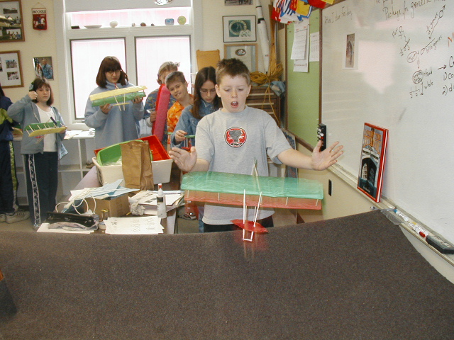
Gliders
were allowed to dry and hung festively from the classroom ceiling until the day
of flight test approached. On flight
test day, each student glued a penny the underside of the lower wing to
increase the mass of the aircraft. A
blanket was stretched out as a safety net to catch gliders that didn’t create
enough lift on launch. Each student
held their own glider by the wingtips and gently pushed it forward into the air
over the blanket. Gliders with enough
forward thrust and sufficient wing camber gently glided in a descending slope
to the blanket. Some stalled. Some never quite reach aerodynamic
configuration in the building process.
It didn’t matter, since every student took an idea off paper, redrew it,
and produced a replica of their own.
What seemed impossible at the beginning of the project had taken wing.