|
|
|
|
|
|
|
|
|
|
|
|
 |
 |
 |
 |
|||||||
|
|
||||||||||
 |
 |
 |
 |
 |
 |
 |
 |
|||
Building and Fire Research Laboratory
Facilities
The Building and Fire Research Laboratory (BFRL) at the National Institute of Standards and Technology is dedicated to the life-cycle quality of constructed facilities. Its performance prediction, measurement technologies, and technical advances enhance the competitiveness of U.S. industry and public safety.
The laboratory studies fire science and fire safety engineering; building materials; computer-integrated construction practices; and structural, mechanical, and environmental engineering. Products of the laboratory's research include measurements and test methods, performance criteria, and technical data that support innovations by industry and are incorporated into building and fire standards and codes. Staff members are involved in more than 100 committees to develop voluntary standards.
The laboratory conducts investigations at the scene of major fires as well structural failures due to earthquakes, hurricanes, or other causes. The knowledge gained from these investigations guides research and is applied to recommendations for design and construction practices to reduce hazards.
The following BFRL Facilities are available for cooperative or independent research, typically on a cost reimbursable basis.
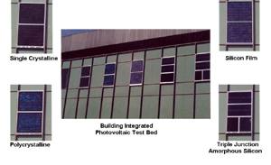
Building Integrated Photovoltaic Testbed
Data is continuously being recorded from the eight photovoltaic panels currently being tested. The long term performance of building integrated photovoltaic panels is measured "in-situ"using the Building Integrated Photovoltaic Testbed, located within the south wall of a a building located on the NIST campus in Gaithersburg, MD. The facility provides comparison between different building integrated photovoltaic panels when exposed to identical meteorological conditions. Up to nine panels can be evaluated simultaneously.
Comparisons are based on energy production, operating temperature, heat flux, and characteristic current versus voltage (IV) curve traces. This "test bed" initially consists of crystalline, polycrystalline, amorphous, and silicon film building integrated photovoltaic products. Two identical panels of each photovoltaic cell technology, one insulated and one un-insulated, are currently installed.
Meteorological instrumentation includes two precision spectral pyranometers, one precision infrared radiometer and two radiatively shielded type-T thermocouples. An ultrasonic wind sensor is used to measure the magnitude and direction of air movement in a vertical plane.
Two systems are used to monitor the building integrated photovoltaic test bed. A "test bed" data acquisition system is used to measure the output signals of the outdoor meteorological instruments, the heat flux transducers, the panel temperature sensors, and two radiatively shielded indoor ambient temperature sensors. This data acquisition system scans the sensors and records the data every five minutes. The second data acquisition system is a custom built photovoltaic measurement system, referred to as a multi-tracer. The multi-tracer simultaneously loads and collects electrical performance data on multiple PV panels. The multi-tracer can operate with a maximum of 14 panels connected.
Capabilities
The building integrated photovoltaic test facility is capable of evaluating up to nine building integrated photovoltaic panels simultaneously. The size of the panels can vary up to a maximum of 1.38 m by 2.36 m. The multi-tracer can dissipate up to 2400 watts. User selectable load options include: (1) peak power tracking, (2) fixed voltage operation, (3) user specific voltage profile and (4) unloaded or open circuited.
Availability
This testbed may be available for use by those outside NIST, but it must be operated by BFRL staff. Collaborative programs may be arranged on cost reimbursable basis.
Contact:
A. Hunter Fanney
(301) 975-5864
email: hunter.fanney@nist.govRoof Photovoltaic Test Facility
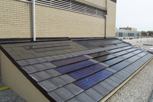
Roof Photovoltaic Test Facility. In order to accurately predict the annual energy production of photovoltaic systems for any given geographical location, building orientation, and photovoltaic cell technology, models are needed that can accurately predict the response of photovoltaic systems for a wide range of environmental conditions. The Building and Fire Research Laboratory (BFRL) recently commissioned a Roof Photovoltaic Test Facility to provide the data needed to develop, improve, and validate the needed simulation models.
The facility is configured to accommodate six residential (sloped roof) and three commercial (flat roof) photovoltaic roofing products. The majority of the currently installed products are referred to as building integrated photovoltaics, as they provide both protection against the elements and produce electrical power. The electrical output of each photovoltaic product is measured every 5 seconds, with average values for these quantities being saved at five minute intervals. The characteristic current versus voltage (IV) curve is periodically swept throughout the day for each test specimen. In addition to the electrical performance of the photovoltaic roofing samples, measurements are made of the coincident ambient temperature, wind speed, and solar radiation incident upon the samples. In addition measurements of diffuse and beam solar irradiance are made by an adjacent meteorological station.
The nine PV roofing products being monitored fall within three general categories of photovoltaic cell technology – single crystalline, poly crystalline, and amorphous silicon – while embodying different manufacturing processes, materials, and design features. The combination of features makes each of the nine roofing products unique and well suited to capture the robustness of simulation models used to predict their electrical performance.
Contact:
Brian Dougherty
301-975-6396
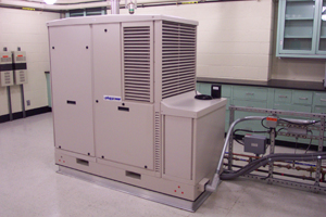
bdougherty@nist.govResidential Fuel Cell Performance Test Facility
Residential Fuel Cell Performance Test Facility NIST has developed a test facility for residential fuel cell systems to determine the performance of these systems on a seasonal basis. The facility was designed to test grid independent, grid interconnected, and stand alone systems with an AC electrical output less than 6 kW. Currently, the test facility is setup to deliver natural gas as the fuel, but only slight modifications would be required to use propane or hydrogen as a fuel. A domestic hot water system has also been developed to determine the amount of useful thermal energy output of the fuel cell system. The test facility encompasses three rooms: an environmental chamber to simulate outdoor ambient conditions, an environmental chamber to simulate indoor ambient conditions, and a control room that houses the data acquisition and control system.
The outdoor environmental chamber houses the main residential fuel cell system, and it can vary the ambient temperature from -18°C to 40°C (0°F to 104°F) and the relative humidity from 20% to 100%. Any equipment that would typically be installed indoors, which would include the domestic hot water storage, pumps, etc., is placed in the indoor chamber. The indoor environmental chamber has the full range of ambient temperatures and relative humidity as the outdoor chamber, but the conditions will be maintained at more typical indoor conditions.
For electrical output to the existing grid, a power analyzer measures the true power, RMS voltage and current, and power factor. To simulate a system that is not connected to the electrical grid, an AC load draws and measures electrical power from the residential fuel cell system. A calorimeter continually monitors the heating value of the fuel entering the system. Thermocouples and platinum resistance thermometers measure the temperature rise of the water used for domestic hot water heating. A turbine and magnetic flow meter measure the flow of water for the domestic hot water system. With these values, all of the energy produced and consumed by the fuel cell can be determined.
The thermal output can be measured using two methods. First, the temperature rise of a stream of water with a constant inlet temperature and flow rate will be used to create a performance map of the steady state thermal output of a system. Also, the facility is able to simulate a typical installation setup that includes a preheat tank warmed by the thermal energy from the fuel cell and an auxiliary tank heated with electricity from the residence. This capability provides a more realistic measurement of the fuel cell system's capability to heat domestic hot water.
Contact:
Mark Davis
301-975-6396
mwdavis@nist.govMobile Solar Tracker Facility
The NIST mobile solar tracking facility is currently being used to characterize solar photovoltaic panels using various cell technologies. NIST’s mobile solar tracking facility is used to characterize the electrical performance of photovoltaic panels. It incorporates meteorological instruments, a solar spectroradiometer, a data acquisition system, and a single-channel photovoltaic curve tracer. Precision spectral pyranometers are used to measure total (beam plus diffuse) solar radiation. Two instruments are used to provide redundant measurements. A pyrheliometer is used to measure the beam component of solar radiation. Long-wave radiation, greater than 3µ m, is measured using a precision infrared radiometer. A three-cup anemometer assembly is used to measure wind speed.
The ambient temperature is measured using a perforated tip, Type-T thermocouple sensor enclosed in a naturally ventilated multi-plate radiation shield. The output signals of the meteorological instruments and thermocouples attached to the building integrated photovoltaic panels are measured using a data acquisition system. Spectral radiation data from 300 to 1100 nm is obtained using a spectroradiometer.
The solar tracker’s photovoltaic array tester measures and records the current and voltage (I-V) characteristics of the panels under evaluation. The array tester is capable of measuring panels or groups of panels with power outputs ranging from 10 watts to 36 kilowatts. Irradiance and temperature loads from a reference cell and thermocouple probe are recorded and used to normalize the data to user selected loads of irradiance and temperature. In addition to sweeping the panel I-V curve and storing the measured values, the curve tracer calculates the values of maximum output power, open circuit voltage, closed circuit current, and fill factor. The data acquisition system can accommodate up to 60 transducers.
Capabilities
The mobile solar tracking facility can be operated in the following tracking modes:
- Azimuth and Elevation Tracking
- Azimuth Tracking
- Elevation Tracking
- Azimuth Tracking with User Selected Offset
- Elevation Tracking with User Selected Offset
- Fixed Position
Up to four photovoltaic modules can be mounted on the facility simultaneously. The facility can be operated over an azimuth range of ± 135° and over an elevation range from horizontal to vertical.
Availability
This apparatus may be available for use by those outside NIST, but it must be operated by BFRL staff. Collaborative programs may be arranged on cost reimbursable basis.
Contact:
A. Hunter Fanney
(301) 975-5864
email: hunter.fanney@nist.govLine Heat-Source Guarded Hot Plate
This large-capacity device measures the thermal resistance of insulation and other low-density materials up to 300 mm thick and 1 m in diameter. The 1-meter guarded hot-plate apparatus measures thermal conductivity of building insulation. This facility provides for absolute measurement of thermal resistance of thick and low-density test specimens used as transfer standards. These standards are used to calibrate heat-flow-meter apparatus (ASTM C 518)or verify guarded-hot-plate apparatus (ASTM C177). This facility is the only one of its kind in the world that will permit low-density thick insulation to be measured with an expanded uncertainty of less 1%.
Capabilities
Laboratory services for thermal resistance measurements (and related thermal properties) are provided for thermal insulation (and building materials) having thermal conductivities of 0.02 W·m -¹·K-¹ to 0. 15 W·m-¹·K-¹. In general, the highest accuracy is obtained for homogeneous specimens.; The preferred size for the test specimen is 1016 mm in diameter; the minimum size, 610 mm square. Customers can supply their own material for specimens, or request NIST to select specimens from an in-house inventory of fibrous-glass material. All tests are performed at an ambient atmospheric pressure of approximately 100 ± 20 kPa (site pressure at Gaithersburg, MD). Services at ambient pressures outside these limits or with other gases are not provided. A dry-air purge is available to reduce the relative humidity to less than 15 percent. Additional information on the apparatus is available in the reference, below. Laboratory capabilities are summarized below.
Thermal
ConductivityTemperature Temperature
DifferenceThickness W·m -¹·K-¹) (K) (K) (mm) 0.02 to 0.05 280-330 20 to 30 13 to 225 0.05 to 0.15 297 20 13 to 25 Availability
This apparatus is available for use by those outside NIST, but it must be operated by BFRL staff. Collaborative programs may be arranged on cost reimbursable basis. Scheduling of services is assigned on a first-come, first-serve basis, determined by receipt of the Order Form and Purchase Order. Services are best when arranged in advance, since turnaround time varies from several weeks to six months depending on the availability of staff and the apparatus
Reference: ASTM C 1043 Adjunct.
Line-Heat-Source Guarded-Hot-Plate Apparatus, ASTM: West Conshocken, Pennsylvania, PCN: 12-310430-61.Contact:
Robert R. Zarr
(301) 975-6436
email: robert.zarr@nist.govFire Emulator/Detector Evaluator
Multi-sensor detector exposed to smolder smoke in the FE/DE. The fire emulator/detector evaluator (FE/DE) is a computer-controlled flow tunnel used to re-create the environments surrounding detectors in the early stages of fire and background environments that give rise to false alarms. The flow velocity, temperature, humidity, carbon monoxide, carbon dioxide, and hydrocarbon gas concentration, and smoke or nuisance aerosol concentration are controlled to emulate burgeoning fire conditions or nuisance sources. The input controls may be obtained from full-scale fire experiments, computer fire models, or heuristic formulations.
Capabilities
The FE/DE can provide control of the flow velocity over a range from 2 cm/s to over 1.5 m/s. Temperature change is achieved by feedback controlled electrical heating elements with maximum temperatures exceeding 80 oC depending on the flow velocity. Carbon monoxide, carbon dioxide, and hydrocarbon gas concentrations are independently controlled via electronic mass flow controllers. Black smoke is generated by a propane diffusion flame burner with smoke concentration controlled by fuel flow and the damper control from the burner to the FE/DE duct. Smokes from cotton smolder and wood pyrolysis represent smolder smoke sources. Nuisance sources include cooking activities, tobacco smoke, humidity and condensing water vapor, and dusts. Routine measurements at the detector location include light extinction, temperature, flow velocity, combustion gas concentrations, and water concentration. Detailed measurements of the aerosol number and mass concentration, and size distribution measurements are possible along with detailed 2-D velocity measurements around detector housings with a 2 component LDV.
Applications
The FE/DE is being used in ongoing research concerning low air speed smoke entrance effects in detectors, test and evaluation methodologies for multi-sensor fire detection, modeling of detector output to support real-time computing of building fire environments, development of algorithms for multi-sensor, multi-function detectors, and emulation of aircraft cargo compartment fire conditions to evaluate current and improved detector designs.
Availability
The facility is used in a variety of BFRL research projects and collaborative projects with other agencies. It also is available on a cost reimbursable basis for independent research but must be operated by BFRL staff.
Contact:
Thomas Cleary
(301) 975-6858
fax: (301) 975-4052
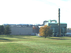
email: thomas.cleary@nist.govLarge Fire Research Facility
The large fire research facility has recently undergone a major renovation for the installation of smoke abatement equipment. As the federal government's principal fire research laboratory, BFRL maintains some of the country's best and most extensive fire testing facilities. More than 400 fire experiments are performed each year in the specially equipped, 27 m (90 ft) x 37 m (120 ft), Large Fire Research Facility.
Capabilities
The facility has three instrumented hoods or calorimeters for measuring heat release rate. Heat release rate is the amount of energy given off by a burning object. The energy is measured in kilowatts (kW). Heat release rate is a primary property used by fire protection engineers for making fire hazard assessments with computer fire models. A small trash can loaded with paper products has a heat release rate of approximately 50 kW. Physically a fire with a heat release rate of 50 kW has flames approximately 0.6 m (2 ft) high with a base of 0.3 m (1 ft) on each side.
The small calorimeter has a capacity of 50 kW and a hood 1.2 m (4 ft) on each side. It is used for measuring the heat release rate of small objects or samples removed from larger objects.
The medium sized calorimeter or furniture calorimeter, has a capacity of approximately 750 kW. This calorimeter is sized for burning individual pieces of furniture or other objects of similar size with a hood measuring 3 m (10 ft) on each side.
The large hood is approximately 5 m (16 ft) x 6 m (20ft) and has a capacity of 3 MW (3,000 kW). Several items can be burned under this calorimeter at one time. Burn rooms built to simulate portions of a building or a house can be installed adjacent to the large room. The smoke from the room fires flow into the large hood for measurement and exhaust from the building.
The Large Fire Research Facility has a variety of instrumentation for measuring temperature, mass, pressure, thermal radiation, real time gas concentrations for oxygen, carbon dioxide, carbon monoxide, nitrogen oxides and hydrocarbons, and smoke concentration. Several computerized data acquisition systems are available in the facility for recording the inputs from the instrumentation.
The facility also has pilot furnace for evaluating the fire endurance of wall assembly or floor/ceiling assembly test specimens measuring 1 m x 1 m.
Applications
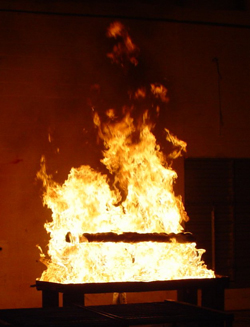
The facility has been used for measuring the heat release rate of a wide variety of items including crude oils, office and home furnishings, and transportation vehicle components. Data from many of the large fire experiments are used to develop or evaluate mathematical models and to study the fire performance of furnishings and interior finish materials. The open space in the facility has housed structures built to simulate living rooms, kitchens, offices, corridors, a townhouse, a bus, a portion of a train car. Measurements on fire suppression systems, such as sprinklers, water mist and gaseous agents, have also been conducted in the the Large Fire Research Facility.
Availability
Contact Alex Maranghides for availability information. For safety reasons, BFRL staff must closely supervise all use of the facilities.
Contact:
Alex Maranghides
(301) 975-4886
email: alexm@nist.govLateral Ignition and Flame Spread Apparatus
This apparatus, developed at BFRL, determines material properties related to piloted ignition of a vertically oriented sample under constant and uniform heat flux up to 6.5 W/cm2 and to aerial flame spread on a vertical surface due to an externally applied radiant flux. The apparatus uses a specimen measuring 162 mm x 806 mm. Analysis of the data yields effective values for the thermal inertia of the material, its ignition temperature, time to ignition, the velocity of lateral flame spread, and a parameter related to flame temperature.
Applications
The data generated are used in current fire growth models and as component elements in fire hazard and fire risk assessment. This apparatus is referenced in ASTM E1321 "Standard Test Method for Determining Material Ignition and Flame Spread" and in ASTM E1317 "Standard Test Method for Flammability of Marine Surface Finishes."
Availability
Industry, university, and government representatives are encouraged to use this facility on a collaborative or independent cost reimbursable basis, with certain restrictions. For safety reasons, BFRL staff supervise the use of the apparatus.
Contact:
Nelson Bryner
(301) 975-6868
email: nelson.bryner@nist.govRadiative Gasification Apparatus
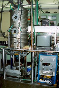
Gasification apparatus with cylindrical exposure chamber at top and sample-load mechanism at bottom. This apparatus, developed at BFRL, determines gasification rate (mass loss rate) of a horizontally oriented specimen exposed in a nitrogen environment to a controlled radiant heat flux from a cone-shaped heater. These non-flaming conditions allow the condensed-phase gasification processes to be de-coupled from complicating gas-phase processes; permit a better estimate of the actual incident heat flux that is producing the fuel gas; and provide a much better view of surface phenomena (e.g., bubbling, charring) during degradation. The cylindrical chamber is 0.61 m in diameter and 1.70 m in height. Two windows provide optical access. The chamber's interior walls are blackened and water cooled to 25 EC to minimize indirect heating of the specimen. The cone-heater temperature is usually fixed at 809 EC to maintain a constant emission spectrum. Changing the distance between the sample and heater can vary incident heat flux to the sample between approximately 25 kW/m2 and 70 kW/m2. A water-cooled shutter is extended to protect the sample from the incident heat flux prior to testing: it also can be used to quickly halt the exposure at any time to "freeze" the remaining sample for subsequent chemical/physical analysis.
Flux levels vary approximately 8-10% across a 0.1 m diameter specimen. Product and ambient gases are removed via an exhaust duct by a constant nitrogen flow of 7.7 l/s at 25 EC. Degradation products can be collected above the specimen's surface and condensed in a cold trap for further chemical analysis. Load cell data are taken every 0.5 s with an uncertainty less than 1% over a 100 g range. Specimens instrumented with thermocouples also can be accommodated.
Capabilities
The gasification apparatus usually is used to study the effects of fire-retardant additives on condensed-phase reactions in synthetic polymers; the data generated provide insight into the chemical and/or physical mechanisms responsible for improved flammability. In addition, the heat of gasification of the specimen, a necessary property for mathematical modeling of the gasification process, can be determined from the data.
Availability
Industry, university, and government representatives are encouraged to use this apparatus on a collaborative or independent cost-reimbursable basis, with certain restrictions.
Contact:
Marc Nyden
(301)-975-6692
email: marc.nyden@nist.govTri-Directional Test Facility
Innovative precast beam-column connections undergoing earthquake motion tests in tri-directional test facility. The tri-directional test facility is a computer-controlled apparatus capable of applying cyclic loads simultaneously in three directions. It is used to examine the strength of structural components or assemblages under the application of a variety of loading conditions, such as might occur during an earthquake or hurricane. This is one of the largest such facilities in the world, both in terms of load capacity and capability to handle, full-scale specimens.
Capabilities
The facility can apply forces or displacements in three orthogonal directions and moments or rotations about three orthogonal axes. Specimens up to 3.3 m in height and 3 m in length or width may be tested. The forces are applied by six closed-loop, servo-controlled hydraulic actuators that receive commands from a computer. Operating under computer control, the facility simultaneously maintains specified loads and/or displacements in each of the six degrees of freedom. Loads may be applied up to 2,000 kN in the vertical direction and 900 kN in each of the two horizontal directions.
Applications
Loads may be cyclic or unidirectional depending on the type of loading condition being simulated. The facility has been used to study shear walls, precast concrete connections, and structural steel sub-assemblages subjected to reverse cyclic lateral loading. This facility supports BFRL's role in conducting research for seismic design and construction standards in the National Earthquake Hazards Reduction Program.
Availability
The facility is used in a variety of BFRL research projects and collaborative projects with other agencies. It also is available on a cost reimbursable basis for independent research but must be operated by BFRL staff.
Contact:
John L. Gross
(301) 975-6061
email: john.gross@nist.govLarge-scale Structures Testing Facility
With its 53 MN (12-million pound) universal structural testing machine, the largest in the world, this facility can test structural components up to 18 m (58 ft) in height. The large-scale structures testing facility consists of a universal testing machine (UTM), and a 13.7m-high reaction buttress equipped with a horizontal hydraulic ram. A combination of 4.5 MN horizontal force and 53 MN compressive vertical force may be applied to large-scale specimens.
Capabilities
The UTM portion of the facility is a hydraulically operated machine of 53.4 MN capacity and is the largest in the world. It is used to test large structural components and to calibrate very large capacity force-measuring devices. It can apply compression forces to column sections or fabricated members up to 18 m in height. The reaction buttress will resist horizontal forces of 4.5 MN at a level of 12.2 m from the floor.
Applications
A testing program was conducted to evaluate the performance of concrete columns 1.5 m in diameter and up to 9.1 m high. Another test series evaluated fracture propagation in steel plates 1 m wide and 0.1 m and 0.15 m thick. Low-cycle fatigue tests, destructive or ultimate loads, earthquake simulation in two dimensions, and complex loading of components may all be accomplished in this facility.
Availability
This facility, which must be operated by BFRL staff, is available for cooperative or independent research on a cost reimbursable basis. Tests should be arranged as far in advance as possible as special hardware may be required.
Contact:
John L. Gross
(301) 975-6061
email: john.gross@nist.gov
HVAC&R Equipment Environmental Chambers
Large Truck Chamber
Air-Conditioner and Heat Pump Outdoor Unit Test Chamber
Large "Truck" Chamber
The large "truck" chamber provides controlled air conditions from -7 °C (20 °F) to 65 °C (150 °F). The conditioning equipment can remove up to 35 kW (120 000 Btu/h) of heat at a dry-bulb temperature of 35 °C (95 °F) and 50 % relative humidity. Full range dry-bulb temperature control of ± 1 °C (2 °F) with relative humidity control better than ± 2 % is possible. At ARI heating and cooling conditions, control of dry-bulb and dewpoint temperatures are better than 0.1 °C (0.2 °F).
Air-Conditioner and Heat Pump Test Chambers
The indoor chamber can provide controlled air conditions for all ARI heating and cooling tests for split-systems, window units, and other unitary equipment throughout the range of 10 °C (50 °F) to 60 °C (140 °F) dry-bulb temperature with relative humidity controlled within ±2 %. The outdoor chamber has a temperature range capability from -18 °C (0 °F) to 60 °C (140 °F) with relative humidity controlled within ± 2%. At ARI heating and cooling conditions, control of dry-bulb and dewpoint temperatures are better than 0.1 °C (0.2 °F). Units with cooling capacities up to 35 kW (120 000 Btu/h) may be tested.
Small Appliance and Refrigerator
This chamber is used to test small heating and cooling equipment such as radiators, heat exchangers, water coolers, refrigerators, and control devices. Dry-bulb temperature may be controlled from -18 °C (0 °F) to 65 °C (150 °F) with relative humidity controlled within ± 2 % of setpoint. At ARI heating and cooling conditions, control of dry-bulb and dewpoint temperatures are better than 0.1 °C (0.2 °F). Maximum heat removal from this chamber is 11.7 kW (40 000 Btu/h).


|
Privacy Policy/Security Notice/Accessability | Disclaimer | FOIA NIST is an agency of the U.S. Department of Commerce |
|
Last updated: 2/28/2007