

|
|
|
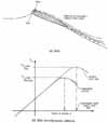
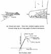
When the slot on a wing is open, the air flows through the slot and over the airfoil. This results in a delay of airflow separation (figure a). Use of a slat allows the airfoil to be flown at a higher angle of attack before a stall would occur (figure b).
The Me-163 is an example of a plane with fixed slots.
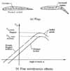
Figure (a) shows a normal airfoil and simple flapped airfoil. Figure (b) shows that the coefficients of lift are increased for all angles of attack.

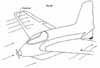
A Fowler flap (figure (a)) is hinged so that it can move back and increase the airplane's wing area. It may also be rotated down to increase the camber. The complex slotted flap shown in figure (b) uses a leading-edge slat and a triple-slotted trailing-edge flap.
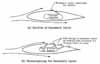
Forms of boundary-layer control.
Figure shows the right spoiler deployed and the left spoiler stowed.

This figure shows a civilian aircraft speed-brake arrangement and two military aircraft dive brake arrangements.
This figure and graph illustrate the increase in drag effect as the wing angle of attack increases
|
Aerodynamic DevicesOn modern aircraft, a large number of aerodynamic devices, such as slats, slots, flaps, spoilers, and dive brakes, affixed to a simple wing serve to increase or decrease lift and drag. With all these devices hanging on a wing, the unsuspecting air traveler might well think that the wing is a piece of modern art. The sound of flaps and slats opening as one approaches for a landing combined with a visual inspection of the wing "coming apart at the seams" may unnerve the unknowledgeable. But a purpose exists for all of these devices, and the safety and economy of air travel depends on them. It is in the interest of safety to perform takeoff and landing at as low a speed as possible. But also, one does not want the normal flying characteristics to be affected. Consider a near-level flight condition in which the airplane weight is equal to the lift (L = W). For minimum flying speed (takeoff or landing), the wing would be operating at maximum lift or CL,max. From the equation for total lift on a wing, L = 1/2 p¥V2S CL where 1/2 p¥V2 = the dynamic pressure, S is the surface area of the wing, and CL = the coefficient of lift, after some manipulation, it is possible to calculate the minimum flight velocity needed for takeoff or landing Vmin,
 The density r ¥ is considered to be constant and if the weight (W) is considered a fixed characteristic of the airplane, then the only way to reduce the minimum velocity Vmin is to increase CL,max and/or the wing area S. Slots and flaps are used for this purpose. The maximum coefficient of lift CL,max may be increased through the use of a slot formed by a leading-edge auxiliary airfoil called a slat. When the slot is open, the air flows through the slot and over the airfoil. The slot is a boundary-layer control device and the air thus channeled energizes the boundary layer about the wing and retards the separation. The airfoil can then be flown at a higher angle of attack before stall occurs and thus get a higher CL,max value. For angles of attack less than the stall angle, however, the airfoil lift curve is relatively unaffected whether the slot is opened or closed. There are two types of slots—fixed and automatic. With the fixed slot, the leading-edge slat is mounted a fixed distance from the airfoil. Its main disadvantage is that it creates excessive drag at high speeds. The German World War II rocket fighter—the Messerschmitt Me-163—had fixed slots in the wing. The automatic slot depends on air pressure lifting the slat away from the wing at high angles of attack to open the slot. At low angles of attack, the slat is flush against the wing leading edge and reduces drag at high speeds compared with the fixed slot. Its main disadvantages are its added weight, complexity, and cost. One main disadvantage of both types of slots is the high stall angle created. The airplane must approach for a landing in an extreme nose-up attitude that reduces visibility. Flaps may be used to increase the maximum lift coefficient, increase the wing area, or both. A change in the maximum lift coefficient may be realized by a change in the shape of the airfoil section or by increased camber. The trailing-edge flap is one method of accomplishing this. The maximum lift coefficient for an airfoil with a simple flap is greater than that for the unflapped airfoil. Also, the coefficients of lift are increased over the entire angle-of-attack range. The stall angle for an airfoil with a simple flap is essentially unchanged from that of the unflapped airfoil. This is opposed to the slot operation where a higher stall angle was obtained. The flapped airfoil reduces the disadvantage that the slot has in high landing angles. A Fowler flap is hinged so that it can move back and increase the airplane wing area. Also, it may be rotated downward to increase the camber. A very large increase in maximum lift coefficient is realized. There are many combinations of slots and flaps available for use on airplanes. For example, the arrangement on a Boeing 737 airplane uses a leading-edge slat and a triple-slotted trailing-edge flap. This combination is a highly efficient lift-increasing arrangement. The slots in the flaps help retard separation over the flap segments and thus enhance lift. It may also be noted that flaps in an extreme down position (50° to 90°) act as a high-drag device and can retard the speed of an airplane before and after landing. Another method of increasing CL,max is by boundary-layer control. The idea is to remove the low-energy segment of the boundary layer and let it be replaced either by high-energy flow from above or by adding kinetic energy to the boundary layer directly. Both of these methods maintain a laminar flow for a longer distance over the airfoil, delay separation, and allow one to get a larger angle of attack before stall occurs, and thus a higher CL,max The slot is one means of passing high-energy flow over the top surface of a wing. The low-energy boundary layer may be sucked through slots or holes in the wing or high-energy air may be blown into the boundary layer through backward facing holes or slots. Spoilers are devices used to reduce the lift on the airplane wing. They may vary the total lift and control the glide angle, as they do on gliders, or on large commercial jets, they may be used to help the aileron control by "dumping" lift on one wing and thus help to roll the airplane. Also, on landing, with spoilers up, the lift is quickly destroyed and the airplane may quickly settle on its landing gear without bouncing. Dive (or speed) brakes are used in airplanes to control descent speed. Whether slowing down quickly when approaching for a landing, after landing, or in a dive, these aerodynamic brakes are helpful. Essentially, they promote a large separation wake and increase the pressure drag. A wing should possess favorable stall characteristics so that (1) the pilot has adequate warning of the stall, (2) the stall is gradual, and (3) there is little tendency to spin after a stall. This may be achieved by "forcing" the stall to occur at the wingroot section first (where the wing meets the fuselage) and let it progress toward the wing tips. The outboard wing-tip stations should be the last to stall so that the ailerons remain effective (are not immersed in a turbulent "dead air" wake). Use of twist, namely washout, is often used so that the wing-root section reaches the stall angle first. Also, airfoil sections with gradual stall characteristics are more favorable than ones with quick stall characteristics. As the inboard root stations stall, turbulent flow from the wing strikes the tail and buffets the pilot's controls. This condition is an adequate stall-warning device. With a gradual stall on both wings, the plane should maintain a level attitude with few spin tendencies. —Adapted from Talay, Theodore A. Introduction to the Aerodynamics of Flight. SP-367, Scientific and Technical Information Office, National Aeronautics and Space Administration, Washington, D.C. 1975. Available at http://history.nasa.gov/SP-367/cover367.htm For Further Reading: Anderson, Jr., John D. A History of Aerodynamics. Cambridge, England: Cambridge University Press, 1997. Montgomery, Jeff, exec. ed. Aerospace: The Journey of Flight. Maxwell Air Force Base, Ala.: Civil Air Patrol: 2000. Smith, Hubert “Skip.” The Illustrated Guide to Aerodynamics. 2nd edition. Blue Ridge Summit, Pa.: Tab Books Inc.1992. Wegener, Peter P. What Makes Airplanes Fly? New York: Springer-Verlag, 1991. Airplane Parts Definitions. (article contains links to descriptions of various aerodynamic devices) http://www.grc.nasa.gov/WWW/K-12/airplane/airplane.html “Wing Design: Other Wing Additions.” http://www.allstar.fiu.edu/aero/Wing33.htm
|