

|
|
|
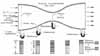
The figure shows the complete setup of a venturi tube and a set of manometers and static taps to measure static pressure. Holes have been drilled into the walls of the venturi tube to measure the static pressure. The block diagrams below the venturi tube show the interchange of dynamic and static pressures all along the venturi tube. The conclusion drawn from this is that the static pressure decreases in the region of high-speed flow and increases in the region of low-speed flow.
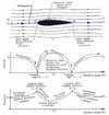
Ideal fluid flow about an airfoil.
|
Ideal Fluid Flow and Conservation of Energy and MassIn order to understand how aerodynamic forces arise, two basic principles must be considered. They are the laws of conservation of mass and conservation of energy, which state that mass and energy can neither be created nor destroyed. These principles are most easily described using the model of an ideal fluid, one that is inviscid, or has zero viscosity, and is incompressible. The continuity equation is a statement of the conservation of mass in a system. Consider a pipe that is uniform in diameter at both ends but has a constriction between the ends, called a Venturi tube. Furthermore, assume that fluid is flowing through the pipe from one end through the narrow throat of the tube with cross-sectional areas A1 and A2, respectively. Let V1 and V2 be the average flow speeds at these cross sections. Assume also that there are no leaks in the pipe nor is fluid being pumped in through the sides. The continuity equation states that the fluid “mass flow rate”—the amount of fluid per unit time—must be the same at any cross section of the pipe or else there is an accumulation of mass—"mass creation"—and the steady flow assumption is violated. Simply stated,
where
This equation reduces to
Since the fluid is assumed to be incompressible, p is a constant and equation (3) reduces to
This is the simple continuity equation for inviscid, incompressible, steady, one-dimensional flow with no leaks. If the flow were viscous, the statement would still be valid as long as average values of V1 and V2 across the cross section were used. By rearranging equation (4), one obtains
Since cross-section A1 is greater than cross-section A2, it can be concluded that V2 is greater than V1. This is a most important result. It states that the flow speed increases where the area decreases and the flow speed decreases where the area increases. In fact, by the continuity equation, the highest speed is reached where the area is the smallest. This is at the narrowest part of the constriction, commonly called the throat of the Venturi tube. The fact that the product AV remains a constant along a tube of flow allows an interpretation of the streamline picture. In the area of the throat, the streamlines must crowd closer together than in the wide part. Hence, the distance between streamlines decreases and the fluid speed increases. The conclusion is that, relatively speaking, widely spaced streamlines indicate regions of low-speed flow and closely spaced streamlines indicate regions of high-speed flow. Assume a fluid flow that, as before, is inviscid, incompressible, steady, and one-dimensional. The energy in the flow is composed of several energies. The kinetic energy arises because of the directed motion of the fluid; the pressure energy is due to the random motion within the fluid; and the potential energy is due to the position of the fluid above some reference level. Bernoulli's theorem is an expression of the conservation of the total energy; that is, the sum total of these energies in a fluid flow remains a constant along a streamline. Expressed concisely, the sum of the kinetic energy, pressure energy, and potential energy remains a constant. If it is further assumed that the fluid flow is horizontal (as, for example, the airflow approaching an aircraft in level flight), then the potential energy of the flow is a constant. Bernoulli's theorem reduces to
where the constant includes the constant value of potential energy. If one considers the energy per unit volume, one obtains the dimensions of pressure and Bernoulli's theorem may be expressed in terms of pressure. The kinetic energy per unit volume is called dynamic pressure q and is determined by q = 1/2pV2 where p and V are, respectively, the fluid flow density and speed at the point in question. The pressure energy per unit volume (due to random motion within the fluid) is the static pressure of the fluid and is given the symbol p. The constant energy per unit volume is called the total pressure pt. Bernoulli's equation reduces to
or
For rotational flow, the total pressure pt is constant along a streamline but may vary from streamline to streamline. In an irrotational flow, the usual case considered for airflow approaching an aircraft, the total pressure is the same constant value everywhere. Bernoulli's equation states that, in a streamline fluid flow, the greater the speed of the flow, the less the static pressure, and the less the speed of the flow, the greater the static pressure. There exists a simple exchange between the dynamic and static pressures such that their total remains the same. As one increases, the other must decrease. Let us now examine how total, static, and dynamic pressures in a flow are measured. When fluid flows around a simple hollow bent tube called a Pitot tube (named after its inventor Henri Pitot) that is connected to a pressure measurement readout instrument, some of the fluid dams up immediately at the tube entrance and comes to rest at the "stagnation point," while the rest of the fluid divides up to flow around the tube. By Bernoulli's equation, the static pressure at the stagnation point is the total pressure (also called the stagnation pressure) since the dynamic pressure reduces to zero when the flow stagnates (comes to rest). (Remember that static pressure + dynamic pressure = total pressure.) The Pitot tube is, therefore, a total-pressure measuring device. A static tube is similar to a Pitot tube except that now the end facing the flow is closed and a number of holes have been drilled into the tube's side. It may also be connected to a pressure-measuring readout instrument as before. Except at the stagnation point, the fluid is parallel to the tube everywhere. The static pressure of the fluid acts at right angles to (or “normal to”) the tube's surface. Since pressure must be continuous, the static pressure at right angles to the holes is communicated into the interior of the tube. The static tube, therefore, with the holes parallel to the flow direction, is a static-pressure measuring device. A combined Pitot-static tube measures the difference between total pressure and static pressure when properly connected to opposite ends of a pressure-measuring readout instrument. By Bernoulli's equation, this difference between total pressure and static pressure is the dynamic pressure, defined as 1/2pV2. If the fluid density p is known, the fluid flow speed can be calculated. In actual use on aircraft, the Pitot-static tube is connected directly to an airspeed indicator that will automatically, by proper gearing, display the aircraft's airspeed to the pilot. The device is sometimes mounted on a boom extending from the airplane's nose to ensure that it measures, as closely as possible, the undisturbed approaching airflow (also called the free-stream condition). —Adapted from Talay, Theodore A. Introduction to the Aerodynamics of Flight. SP-367, Scientific and Technical Information Office, National Aeronautics and Space Administration, Washington, D.C. 1975. Available at http://history.nasa.gov/SP-367/cover367.htm For Further Reading: Anderson, Jr., John D. A History of Aerodynamics. Cambridge, England: Cambridge University Press, 1997. Hewitt, Paul G. Conceptual Physics. Sixth Edition. Glenview, Ill.: Scott, Foresman and Company, 1989. Wegener, Peter P. What Makes Airplanes Fly? New York: Springer-Verlag, 1991.
|